|
|
Post by Deleted on Jan 14, 2020 10:08:30 GMT
|
|
|
|
Post by keith1500 on Jan 15, 2020 13:30:07 GMT
Thanks for that additional snippet of info. I have some reamers on order plus I’ll get one or two others at the show on Friday plus some more appropriate drills. I think I have pushed my luck in the past not having the right size drill bit and asked too much of a reamer. Good to refresh/ relearn some of these basics. Delaplume On your comment about better quality rules. I don’t think I have the eyes to match anymore! I often find myself using a 20times or a watchmakers loupe as I did with this exercise.... Sanity check. Just marking up the diagonal holes and checking the distance between them where they enter the steam chest. Doing this gave me the idea that I might use the vee block as my 45 degree angle.  Simple single cylinder steam engine Simple single cylinder steam engine by GL5Keith1500, on Flickr |
|
|
|
Post by delaplume on Jan 15, 2020 15:48:40 GMT
Quote}------"Delaplume On your comment about better quality rules. I don’t think I have the eyes to match anymore! I often find myself using a 20times or a watchmakers loupe as I did with this exercise"..... .Me too, matey !!...me too LoL !!.........but the info remains sound..Look at the etchings for the 1/100 and you'll see that the gap is about the same as the line thickness..ie the line is approx. 1/100 inch or 0.010"..........So by using our "young eyes" ( or to-day's magnifier ) and the edge of the caliper jaws if you split the line you can work to + or - 0.005" by hand alone..........Do remember this is an approximation only, but you won't be all that far out.............As a final year Apprentice we weren't allowed access to Micrometers etc untill we were within 0.010" !!........It's made all the more interesting if you only have a "Firm Joint" hand caliper which has to be tapped gently for adjustments... When it comes to machining the metal then "Ridgidity" is the name of the game.......Don't be lulled into thnking that because the item is small you can hold it by hand !!....... SOD'S LAW}---- If a drill is going to wander off-course it'll do so just when you don't want it to !! There are plenty of adjustable machine vices on the market, and you can still do final vertical checking via your engineers square alongside............Here's an example}-------  |
|
jasonb
Elder Statesman

Posts: 1,209
|
Post by jasonb on Jan 15, 2020 19:51:44 GMT
I'd just hold it in your regular mill vice, use the Vee block or something to set the angle not really worth buying a tilting vice unless you expect to get a lot of use out of it. Start the holes with a ball nosed milling cutter of FC-3 type. 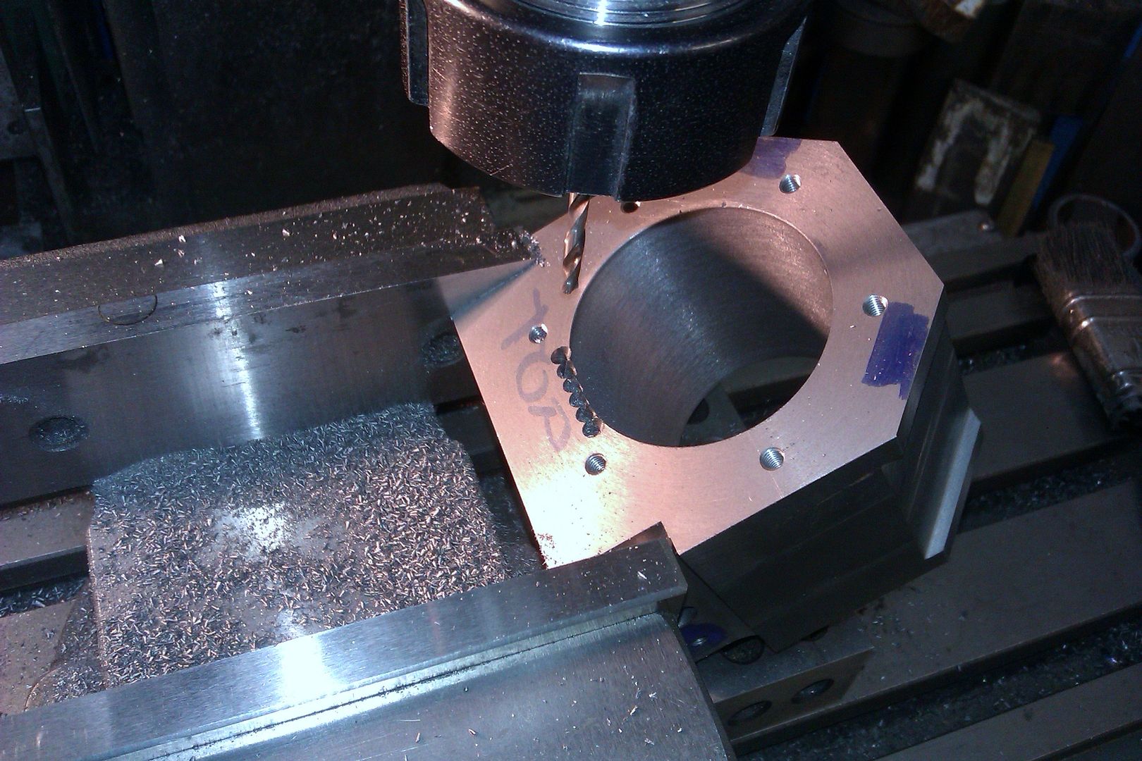 |
|
|
|
Post by Deleted on Jan 15, 2020 20:14:04 GMT
A digital angle gauge would be good for this, cheaper than a tilting vice too. As Jason said use a normal machinevice and hold it at the correct angle. As it's 45 degrees then yes use the block, if an unusual angle, in the past I have chocked the job up at the correct angle using a digital gauge to check the angle. Just be sure that the job is resting on whatever you have used to raise one corner fully, it's also important to have something clamped to form a chock to remove any chance of the job slipping.
Regards
Pete
|
|
|
|
Post by keith1500 on Jan 15, 2020 20:29:18 GMT
I'd just hold it in your regular mill vice, use the Vee block or something to set the angle not really worth buying a tilting vice unless you expect to get a lot of use out of it. Start the holes with a ball nosed milling cutter of FC-3 type. What is a FC3 type of milling cutter? I have bull nose but never though of using it to start a hole. I was going to mill a flat, centre drill it and then drill out 3.5mm as per the design. Keith |
|
|
|
Post by simplyloco on Jan 15, 2020 20:57:08 GMT
I'd just hold it in your regular mill vice, use the Vee block or something to set the angle not really worth buying a tilting vice unless you expect to get a lot of use out of it. Start the holes with a ball nosed milling cutter of FC-3 type. What is a FC3 type of milling cutter? I have bull nose but never though of using it to start a hole. I was going to mill a flat, centre drill it and then drill out 3.5mm as per the design. Keith FC-3 is a budgie 3 flute 'disposable' milling cutter. Velly cheep! John |
|
|
|
Post by keith1500 on Jan 15, 2020 22:19:02 GMT
Ahhhh, I see.
|
|
|
|
Post by delaplume on Jan 16, 2020 1:52:01 GMT
There are cheaper versions available ---- this type is approx £35 and the whole of the job piece is held within the vice jaws ...  |
|
jasonb
Elder Statesman
Posts: 1,209
|
Post by jasonb on Jan 16, 2020 8:02:31 GMT
I find the 3 flute end cutting FC-3 cutters are better for plunging than the typical 2-flute "slot drill" and as has been said they are quite economical to buy and mostly what I use on the manual mill for anything 6mm (1/4") or less.
|
|
stevep
Elder Statesman
Posts: 1,070
|
Post by stevep on Jan 16, 2020 9:44:02 GMT
An advantage of the FC-3 cutter is that they are equipped with a flat for a grub-screw to hold them in the special holders intended for them. This ensures they don't work their way out of the chuck - which can happen with both drill chucks and even collets. You can see the holder in this picture of machining the passages on my Pansy cylinder.  |
|
|
|
Post by keith1500 on Jan 16, 2020 10:28:37 GMT
An advantage of the FC-3 cutter is that they are equipped with a flat for a grub-screw to hold them in the special holders intended for them. This ensures they don't work their way out of the chuck - which can happen with both drill chucks and even collets. You can see the holder in this picture of machining the passages on my Pansy cylinder. Yes I noticed that on some of the cutters I have. I guess, being cheap one, they happen to be FC-3 but I never realised that’s what they were. What more interesting your picture is the set up. Are you using sine bars to get the angle? |
|
stevep
Elder Statesman
Posts: 1,070
|
Post by stevep on Jan 16, 2020 11:31:02 GMT
It's a home-made 'sine table'. Same principle, but wider (about 3 inches).
|
|
|
|
Post by keith1500 on Jan 18, 2020 22:25:24 GMT
I figured that if everything was accurate, given a few calculations, I should be able to take advantage of the mill DRO to locate the drilling position of the steam port. With the block set at 45 degrees a few calculations indicated the if I moved 45.58mm from the reference point I would be on target.  Simple single cylinder steam engine Simple single cylinder steam engine by GL5Keith1500, on Flickr The reference point being established. Care taken to make sure it is registered on the maximum circumference. I suspect a cylindrical edge finder would have been better here.  Simple single cylinder steam engine Simple single cylinder steam engine by GL5Keith1500, on Flickr Having centred the block I then moved in 45.58mm and cut a face with a 1/8th end mill. Then I used a centre drill, followed by a 2mm, then 1/8th drill.  Simple single cylinder steam engine Simple single cylinder steam engine by GL5Keith1500, on Flickr The ports look to be right. Nicely at the end of the cylinder but not under the cover.  Simple single cylinder steam engine Simple single cylinder steam engine by GL5Keith1500, on Flickr |
|
|
|
Post by Roger on Jan 18, 2020 22:47:49 GMT
Hi Keith,
This is a much better method than trying to set it up by eye, even though it's not ideal to set up to a corner. I've used this method several times to good effect. I only have a ball on my wobbler too, but you can always move it up and down slightly as you approach the point where it flies away so that you know it's found the full diameter of the wobbler ball.
As an aside, it's easy to find any offsets from this kind of feature to a corner for example when you're using 3D modelling.
Glad to see you're getting good use out of the 2x3x4 blocks, if that's the size you have.
|
|
|
|
Post by keith1500 on Jan 18, 2020 22:59:26 GMT
Hi Roger,
Yes I did as you said move the up and down to check I was on the full diameter. It worked well.
The Centec’s table is only 12inches by 4 inches and the 1,2, 3 blocks are ideal.
Indeed CAD is terrific for giving you those dimensions and without errors of a miscalculation ! I must get a cad package....
Keith
ps Great catching up with you at Ally Pally.
|
|
|
|
Post by keith1500 on Jan 20, 2020 23:33:03 GMT
|
|
stevep
Elder Statesman
Posts: 1,070
|
Post by stevep on Jan 21, 2020 10:05:29 GMT
At the risk of trying to tell someone how to suck eggs, when holding a piece of work at one end of the jaws of a machine vice, it is good practice to have a piece of a similar dimension at the other end of the jaws to make sure there is no tendency for the moving jaw to twist. This ensures a much firmer hold on the work piece.
|
|
|
|
Post by keith1500 on Jan 21, 2020 12:51:49 GMT
I did think that but the vice being nice and new is sweet, I felt I could be lazy on this occasion. If I was milling I would have certainly considered that.
Anyway, thanks for the heads up on that. Much appreciated.
|
|
|
|
Post by keith1500 on Jan 23, 2020 22:55:11 GMT
Working on the shaft support and bearing cap. Reaming the joining holes of both parts to ensure good alignment. Once these parts are bolted together and aligned the next step would be the 8mm diameter shaft hole.  Simple single cylinder steam engine Simple single cylinder steam engine by GL5Keith1500, on Flickr The base plate and it’s brass components in various states of manufacture along with the cylinder block etc. Note the long shaft support has a slight recess the ensure the bearing cap locates nicely.  Simple single cylinder steam engine Simple single cylinder steam engine by GL5Keith1500, on Flickr |
|


