|
|
Post by keith1500 on Jan 24, 2020 22:13:50 GMT
Although I have set out all the holes using the mill and bang on co-ordinates something was not quite right when I came to fitting a test shaft. The alignment of the two bearings is slightly out. Ideally I would have like to have run the reamer though both I order to get a true inline pair of holes but the reamer was not long enough and it’s shank was 8.3mm which was a shame as I could have got away with doing it that way. Do the shanks on reamer not match their size? Does this vary? What I should have done here is clock the bearing block and the base to make sure it was square and true.  Simple single cylinder steam engine Simple single cylinder steam engine by GL5Keith1500, on Flickr The build so far. The test shaft has been run in and runs well enough but has a little more play than I would have liked.  Simple single cylinder steam engine Simple single cylinder steam engine by GL5Keith1500, on Flickr |
|
|
|
Post by Roger on Jan 24, 2020 22:17:07 GMT
Hi Keith,
I don't think there's any general rule you can apply about the shank on a reamer. Some are just under the nominal size so you can run them right through, others are bigger and some have a large morse taper. It all depends on the manufacturer and the size.
|
|
|
|
Post by keith1500 on Jan 24, 2020 22:29:35 GMT
Hi Roger,
In future i might try to be more selective and choose ones with a smaller shank as these would offer a bit more scope.
The 8mm one is part of a set I brought from amazon. The price was worth taking a chance on.
Keith
|
|
|
|
Post by Roger on Jan 24, 2020 23:11:13 GMT
There are some truly awful reamers out there. Personally I bite the bullet and pay top dollar for them from industrial suppliers such as 'Drill service horley'. No connection just a satisfied customer.
|
|
|
|
Post by springcrocus on Jan 24, 2020 23:12:51 GMT
Do the shanks on reamer not match their size? Does this vary? They start life slightly oversize to allow for precision grinding of the flutes and flanks. Dormer and Presto parallel-shank reamers used to be made from ground stock 0.05mm oversize for metric reamers and two thou oversize for imperial reamers. That was thirty years ago: nowadays, who knows? Regards, Steve Oops!  I meant to write 0.005mm and two tenths of a thou. Steve. |
|
|
|
Post by keith1500 on Jan 25, 2020 21:25:27 GMT
I borrowed a decent 8mm reamer to run through the two bearing points and like you say it was a fraction over size but not monstrously over size like my one! Shaft alignment now sweet. Talking of using reamers; I decided to make a slight change to the upright supports part 1-02.2 . Instead of fully threading them I only threaded what was required, leaving a 6 mm section to engage with the hole. The holes in parts 1-01.3 &1-01.5 at the bottom and part 1-02.1 at the top were reamed 6mm to ensure secure and proper alignment. This has worked well.  Simple single cylinder steam engine Simple single cylinder steam engine by GL5Keith1500, on Flickr |
|
|
|
Post by keith1500 on Jan 26, 2020 21:53:54 GMT
Today’s exercise was the finish the base. This required the supports finishing with radius being applied and the base plate required the holes for the supports putting in, the recess for the crank and the holes for the eccentric squared off. First job clean up the supports and apply the radius. So, a gentle centre punch mark and scribe the radius to the four corners requiring 10mm radius ( this is on the inside surface of the supports). After this the pair were bolted together. The usual technique of joining a series of flats to form the radius.  Simple single cylinder steam engine Simple single cylinder steam engine by GL5Keith1500, on Flickr With the supports in place the the recess for the crank could be accurately positioned. With the job well out of the vice and fair bit of vibration going on this took a bit of time gently eating away the millimetres (making dust rather then swarf!)  Simple single cylinder steam engine Simple single cylinder steam engine by GL5Keith1500, on Flickr The base plate and supports complete.  Simple single cylinder steam engine Simple single cylinder steam engine by GL5Keith1500, on Flickr |
|
|
|
Post by keith1500 on Jan 29, 2020 23:21:30 GMT
The next part I fancied making was the shaft and crank. I was worried about getting the crank to run true on the shaft so my logic was to turn the disc to size on the shaft. The first job was the make a disc near to size with a hole for press fitting the shaft. Before I could press on the shaft I needed to position the crank hole. This was done on the mill. I wasn’t too sure about finding the centre of the shaft hole (7.9 mm) so I used the small disc wobbler which seem to work ok. The crank hole was only touched by the tip of the reamer to ensure the crank is a good press fit.  Simple single cylinder steam engine Simple single cylinder steam engine by GL5Keith1500, on Flickr The shaft was pressed into the disc with a 10mm stub on the other side. This allowed the disc to be faced off true.  Simple single cylinder steam engine Simple single cylinder steam engine by GL5Keith1500, on Flickr Then the shaft was put in the chuck and the disc finished to size. |
|
|
|
Post by Roger on Jan 30, 2020 8:17:28 GMT
Hi Keith,
That's coming along really nicely, and at quite a pace. You'll have it finished in no time at this rate.
For setting up to a hole like that, I use a 2 micron lever clock on a miniature magnetic base. I use the parallel sided Morse taper holder for that because the magnet sticks to that nicely. The stylus on those clocks are so small that you can clock up on a hole that's around 2mm if you need to. It's worth getting an arrangement like that, you can clock up just about anything with it. That's what I use for all of my setups.
|
|
|
|
Post by keith1500 on Jan 30, 2020 8:39:52 GMT
Of course the mistake or error I made was not taking opportunity to drill two 4mm holes which would form the 2mm radius of the crank shape.. So, I decided to mount the disc on a block of aluminium. One advantage of this would be to align the shaft and crank pin on the X axis of the machine and then allow setting out of the crank shape. It was while positioning then holes I questioned if they were right. This lead to me blueing the disc and then had the idea that if I dragged the centre drill across the disc I could mark out the crank. 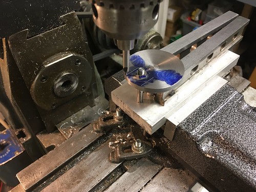 Simple single cylinder steam engine Simple single cylinder steam engine by GL5Keith1500, on Flickr The only line I had to do by hand was from the hole to the 1.5mm mark. This is the crank ready for cutting out.  Simple single cylinder steam engine Simple single cylinder steam engine by GL5Keith1500, on Flickr |
|
|
|
Post by keith1500 on Jan 30, 2020 8:44:13 GMT
Hi Keith, That's coming along really nicely, and at quite a pace. You'll have it finished in no time at this rate. For setting up to a hole like that, I use a 2 micron lever clock on a miniature magnetic base. I use the parallel sided Morse taper holder for that because the magnet sticks to that nicely. The stylus on those clocks are so small that you can clock up on a hole that's around 2mm if you need to. It's worth getting an arrangement like that, you can clock up just about anything with it. That's what I use for all of my setups. Hi Roger, I noticed that in one of your recent photos when making the valve handles for your injectors. The clamp looked interesting. Was it home made? Can you provide a few photos of the items you mention above? That would give me a better idea of what to go for. Thanks Keith |
|
|
|
Post by Roger on Jan 30, 2020 9:23:53 GMT
Hi Keith, Here are a couple of closeups of the adjuster I made which is a real time saver. If I made another one, I'd make it even shorter which would help in some situations. I can move the clock up and down using the thumbscrew so that the stylus moves about 4-5mm which is more than enough. There's a small spring inside to hold the arm against the adjusting screw. You can see that I've taken a grinding point to the inside of the ball joint to allow it to fold back on itself more. Again, that really helps in some situations.  20200130_091348 20200130_091348 by The train Man, on Flickr 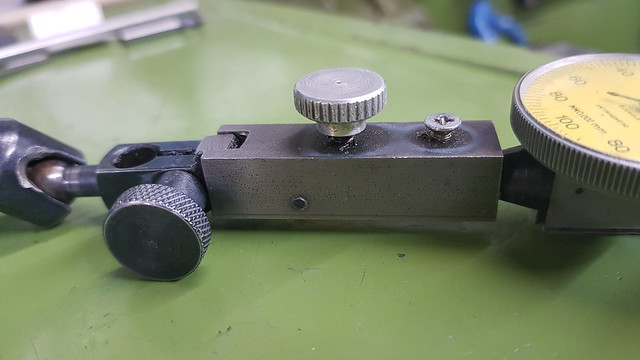 20200130_091403 20200130_091403 by The train Man, on Flickr |
|
|
|
Post by keith1500 on Feb 2, 2020 18:54:06 GMT
All behind with updates... Here’s how I progressed the crank. Having hacksawed way the waste the next step was to either file or mill the edges. Milling would give a better finish and using the set up shown above the two parallel sides where easily milled using 3mm dia cutter taking 0.1 mm cuts. This worked very well and so the challenge was now to do the two angled edges. This could be done by rotating the crank so the edge lays on the X axis. I figured I could do this by locating the crank pin in the appropriate corresponding position. I played with the dimensions given and found the angles involved. Then figured out the new X and Y co-ordinates for the pin. 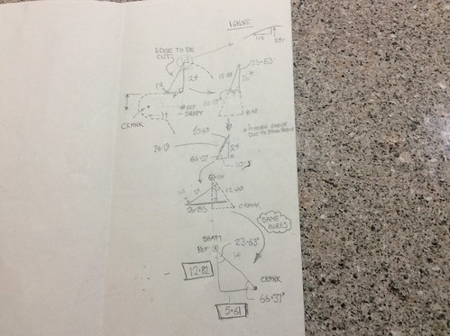 Simple single cylinder steam engine Simple single cylinder steam engine by GL5Keith1500, on Flickr Machining the angled edge with the crank pin in the new position. 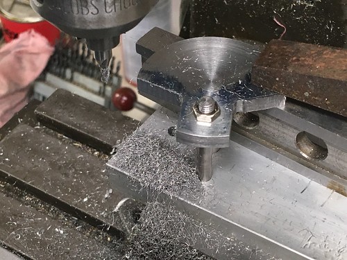 Simple single cylinder steam engine Simple single cylinder steam engine by GL5Keith1500, on Flickr Filing the radius using good old buttons.  Simple single cylinder steam engine Simple single cylinder steam engine by GL5Keith1500, on Flickr Finished crank ( minus the pin)  Simple single cylinder steam engine Simple single cylinder steam engine by GL5Keith1500, on Flickr |
|
|
|
Post by keith1500 on Feb 2, 2020 20:14:00 GMT
Today’s job raised a few questions. Firstly I made a trepanning tool based on a YouTube video youtu.be/6PcEBaset1II am not sure I got it quite right as it behaved like a horrible parting off tool. I tried different speeds but in the end run at a moderate speed and got on with it! I found that by taking a cut as I moved across the face it wasn’t too bad. I did wonder if it was down to the quality of the chuck which was real cheap; was this the source of the vibration? Or was the tool too wide. It has to be fairly wide given the 16mm plunge. Any thoughts ? The other question was how to hold the flywheel so as not to damage the finish? See last photo. Flywheel was machined using a trepanning tool.  Simple single cylinder steam engine Simple single cylinder steam engine by GL5Keith1500, on Flickr To make sure the flywheel run true I chose not to ream the 8mm hole but bore it.  Simple single cylinder steam engine Simple single cylinder steam engine by GL5Keith1500, on Flickr After polish8mg. Ready for parting off.  Simple single cylinder steam engine Simple single cylinder steam engine by GL5Keith1500, on Flickr To machine the other side I need to hold the wheel in a chuck and protect the finish. Will shim be ok and safe?  Simple single cylinder steam engine Simple single cylinder steam engine by GL5Keith1500, on Flickr |
|
|
|
Post by Roger on Feb 2, 2020 20:41:47 GMT
Hi Keith,
That worked out rather well, and you've ended up with a nice finish too.
I don't know what your head bearings are, but plain bearings need enough clearance to work, and that's exactly what you don't want with a wide tool that's going to ring like a bell unless everything is very rigid. Looking at the tool, it's not clear whether there's enough clearance to miss the outside radius you're creating. I use a HSS drill blank for this sort of tool so you get the clearance by default.
Making it narrower probably wouldn't have helped much because it's got to be deep, and that would mekd the tool even more springy. A bigger lathe is what you really need for this sort of job, one with taper roller bearings. You're always going to struggle on a small lathe with this sort of setup. Having a variable speed drive so you can slow it down to a crawl would probably help a bit, and that would also fold back if it all goes pear shaped and it jams up!
|
|
jasonb
Elder Statesman

Posts: 1,209
|
Post by jasonb on Feb 2, 2020 20:44:01 GMT
Aluminium drink can is a bit softer to use as packing, best to cut a long strip and wrap around part rather than 3 small bits which drop in the swarf tray and are likely to slice your fingets. 0.1mm DOC seems very shallow and will soon take the corner off your cutter, 0.5mm would be better on a light machine for a 3mm dia cutter. Width of tool was the main problem, I prefer a narrower ended tool with a slight radius feeding in as it is moved across the surface, I cut to the outer edge and take out most of the waste running the normal way and then do the side of the hub on the back side with lathe in reverse, you can add a bit of draft angle too to get the "cast" look all at one setting. Take care if you have a screw on chuck! 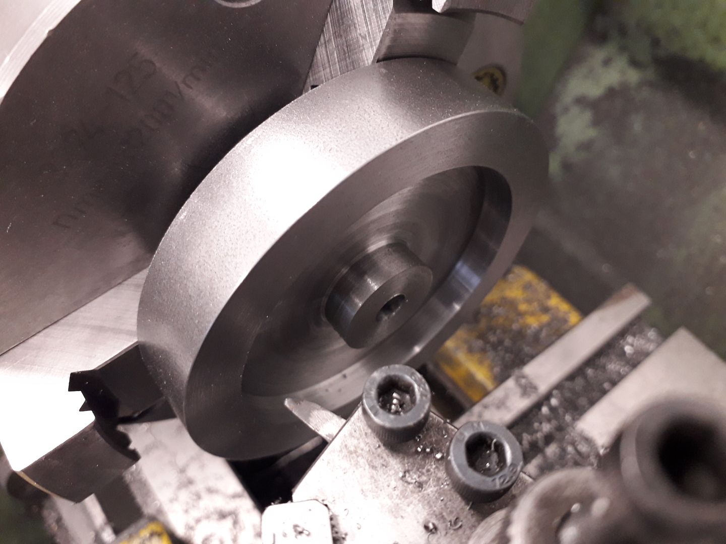 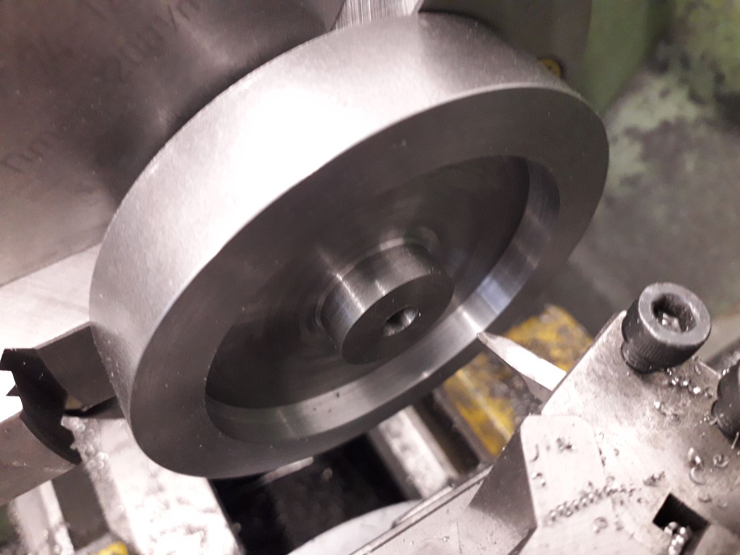 |
|
|
|
Post by keith1500 on Feb 4, 2020 17:52:47 GMT
Aluminium drink can is a bit softer to use as packing, best to cut a long strip and wrap around part rather than 3 small bits which drop in the swarf tray and are likely to slice your fingets. 0.1mm DOC seems very shallow and will soon take the corner off your cutter, 0.5mm would be better on a light machine for a 3mm dia cutter. Width of tool was the main problem, I prefer a narrower ended tool with a slight radius feeding in as it is moved across the surface, I cut to the outer edge and take out most of the waste running the normal way and then do the side of the hub on the back side with lathe in reverse, you can add a bit of draft angle too to get the "cast" look all at one setting. Take care if you have a screw on chuck! I recalled successfully using masking tape on sheet material placed in our Carvey machine for labels. Here is place tape on the material and corresponding tape on the bed. Then stick the two together using super glue. Surprising how much grab that has. So used that, as you will see. The 0.1 cut worked very well. Mainly inspired by Rogers work using his mill. Ok, I am not CNC but I can manually cut simple straights using small tool and it worked. Yes I think I agree with you the width of the tool is the problem. Still got away with it and thankfully I wasn’t making rings like that chap in the video. Thanks for posting a photo of your trepanning set up. Keith |
|
|
|
Post by keith1500 on Feb 4, 2020 17:59:35 GMT
 Simple single cylinder steam engine Simple single cylinder steam engine by GL5Keith1500, on Flickr Last night I machined the back of the flywheel. I put two layers of masking tape around the wheel and then two turns around each jaw. Loaded the wheel and clocked it true. Then lifted each jaw in turn and applied glue to join the tape together. Readjusted the wheel to run true and left it for an hour. Took light cuts of 0.25mm and it worked out fine. Next job is a polish then we’ll see if there are any marks..... hope not! |
|
|
|
Post by delaplume on Feb 4, 2020 19:22:50 GMT
An old style HT ignition coil has a laminated soft iron core which, after draining the light oil from inside, can be dis-assembled and gives approx. 50 or more thin strips about 1/2 inch wide by 3 inch long .......... They make great toolpost packing pieces etc..  |
|
|
|
Post by Roger on Feb 4, 2020 22:13:40 GMT
Simple single cylinder steam engine by GL5Keith1500, on Flickr Last night I machined the back of the flywheel. I put two layers of masking tape around the wheel and then two turns around each jaw. Loaded the wheel and clocked it true. Then lifted each jaw in turn and applied glue to join the tape together. Readjusted the wheel to run true and left it for an hour. Took light cuts of 0.25mm and it worked out fine. Next job is a polish then we’ll see if there are any marks..... hope not! That's certainly a novel approach, although not one I'd use myself. I'd go for Aluminium between the jaws and the part because soft material is likely to relax and leave the part prone to shifting, particularly if you're using coolant. |
|


