|
|
Post by coniston on Feb 24, 2020 22:14:48 GMT
Nicely recovered, good job.
Chris D
|
|
|
|
Post by keith1500 on Feb 25, 2020 7:26:00 GMT
Thank you. Fortunately, the part being brass meant it would be hard to spot the silver solder used in the repair.
|
|
|
|
Post by Roger on Feb 25, 2020 8:02:01 GMT
I should have noticed this earlier. The 5mm hole that forms the 2.5mm radius wasn’t in the right position. Odd, as this was placed at the same time as the threaded hole for the piston rod. Two choices, either start again or try to recover the job. I decided to try and recover the job by silver soldering in place a plug. The. Machine out the slot and see how it looked.  Simple single cylinder steam engine Simple single cylinder steam engine by GL5Keith1500, on Flickr Happy with the result the cross slide was then finished to size. I used two lengths of 5mm square which located nicely in the guides mainly due to the scale left from silver soldering. These sat on a pair of parallels which in turn clamped the part in place. This ensured everything was relative to the guides.  Simple single cylinder steam engine Simple single cylinder steam engine by GL5Keith1500, on Flickr The last job was the file the 6mm radius. Some of the filing was done with a file in the vice and the part moved along the file. Final filing was draw filing with a needle file followed by emery cloth guided by the roller ( filing button).  Simple single cylinder steam engine Simple single cylinder steam engine by GL5Keith1500, on Flickr The cross slide fitted beautifully and runs nicely in the guides.  Simple single cylinder steam engine Simple single cylinder steam engine by GL5Keith1500, on Flickr Hi Keith, That was neatly recovered. When you say "this was placed at the same time as the threaded hole for the piston rod" I'm not sure how that was possible since they are at 90 degrees to each other. Perhaps you mean that you turned it round in the vice and assumed it was still lined up correctly to the fixed vice jaw? I've been caught out by assumptions like that, especially when the part is set higher out of the vise. These days I like to use the wobbler on both sides and find the average rather than work off one datum face when I need to find the middle of something. |
|
|
|
Post by keith1500 on Feb 25, 2020 11:24:42 GMT
Roger,
Yes, that’s pretty much what I did. I wobbled on the fix jaw of the vice and then set a stop which was a tool makers clamp and this was wobbled using a parallel. Then using the centre line I placed the hole for the boss. Turned the brass through 90 degrees and placed the 5mm hole. Somewhere there the centre line shifted. I am sure I kept to the he same reference edge on the material but who knows. It’s one of those errors that can flaw a job.
Talking of finding middles. I have noticed when using the wobbler that I get errors of 0.1mm. Say I wobble the first side and set this to zero, then go to the other side and I get a value of 12.66mm the centre should be 6.33. I go to 6.33 and zero. Then check by going to either side again. I would expect the readings to be +6.33 and -6.33 but often I get +6.23 and the other -6.43, or similar which indicates the centre is not quite right.
Is this a phenomenon of wobbling different sides or is my wobbler a faulty?
|
|
jasonb
Elder Statesman

Posts: 1,209
|
Post by jasonb on Feb 25, 2020 13:16:10 GMT
Sounds like your wobbler assuming you are using a DRO and not suffering backlash issues. You don't say what type of wobbler but if the ball and socket type don't have them done up too tight and make sure there are no burrs on the work to affect readings. I tend to use an electronic one that lights up when it makes contact (rigid end not sprung ball)that is quicker and repeatable.
|
|
|
|
Post by Roger on Feb 25, 2020 14:44:12 GMT
Roger, Yes, that’s pretty much what I did. I wobbled on the fix jaw of the vice and then set a stop which was a tool makers clamp and this was wobbled using a parallel. Then using the centre line I placed the hole for the boss. Turned the brass through 90 degrees and placed the 5mm hole. Somewhere there the centre line shifted. I am sure I kept to the he same reference edge on the material but who knows. It’s one of those errors that can flaw a job. Talking of finding middles. I have noticed when using the wobbler that I get errors of 0.1mm. Say I wobble the first side and set this to zero, then go to the other side and I get a value of 12.66mm the centre should be 6.33. I go to 6.33 and zero. Then check by going to either side again. I would expect the readings to be +6.33 and -6.33 but often I get +6.23 and the other -6.43, or similar which indicates the centre is not quite right. Is this a phenomenon of wobbling different sides or is my wobbler a faulty? Personally I wouldn't ever use a stop for anything other than rough work. Nicks, marks and burrs can make a big difference to the way the part sits, and you also can't really tap the part down onto parallels to get it flat if you have a stop there that might move. Using a wobbler off one edge is not going to be as accurate as touching both sides in my opinion, and I always make sure the wobbler is at precisely the same height. Those differences seem really large to me, you ought to be able to get it within +/-0.01mm in my opinion with that method. I made my own wobbler which has a very light spring indeed. I suspect your wobbler is too tight, and that will affect the sensitivity. You ought to be able to loosen it or wind a new spring. Mine is barely strong enough to support the weight of the arm if I hold it horizontally. Wobblers are preferable to electronic type in my opinion. That's because they take account of any runout in the holder, and that can be significant. You need to approach the end position very slowly indeed to get the best accuracy. Remember, the wobbler only touches once per revolution, and you can't have it running too fast. So however far you move it in one revolution is the limit of the accuracy you can acheive. You also have to be aware that if you alter the height the head is above the work between using the wobbler and using the drill, that can introduce an error. The same thing goes with locking the head. If you're going to drill a hole with the head unlocked, you need to use the wobbler with the head unlocked. The reverse applies if you're milling with a locked head. This is for a machine like mine with a separate quill and knee of course. Locking any axis is almost certainly going to move is slightly. |
|
jasonb
Elder Statesman
Posts: 1,209
|
Post by jasonb on Feb 26, 2020 8:31:50 GMT
The accuracy of touching one or two sides is very much dependant on what equipment you have. Like Roger I will mostly touch off both sides and simply use the DRO to "half" the readings and then work from the middle. However I only do this on my mill that has the DRO when working on the other one it is more accurate to touch one side and one edge and then work from that corner as you can always feed in the same direction and this makes it far easier to allow for any backlash. If you were touching both side on a non DRO machine you would find it much harder and therefor less accurate to determine where the middle of the two readings should be.
|
|
|
|
Post by keith1500 on Feb 26, 2020 16:56:36 GMT
I think some of the problem is with my Centec 2 mill. She is a small machine. At the end of the day I brought for a £180. It was worn with lots of backlash however, my intention was to use it for laying out hole arrays accurately, mainly for wagon building. But you know what it’s like, we tend to push the boundaries, challenge ourselves and do all-sorts of jobs on these things. So its gone from doing holes to basic milling, to making fairly accurate bits and now more challenging milling with this project. One of the first things I did was fit a very basic amateur type DRO system using Chinese digital rules wired back to ShumaTech DRO kit. www.shumatech.com/web/products/dro-350Real entry level stuff. But it was an amazing improvement to the machine and what I achieve with it. The next limitation was the height under the quill. Someone was making raising blocks for the Centec. Not cheap and not available at the time. So I made one out of a six inch RSJ with two slabs of 1inch Steel welded on the top and bottom. Stress relived one evening in a big bonfire and then this was machined up on my mates old Liilian mill. At the time I never thought double checked anything. Certainly didn’t check the set up of the mill for it’s accuracy. Just took it as good. Anyway the block worked a treat and again opened up what we could do. But I know know it caused a slight nod. It wasn’t until I was matching a replacement part for a L frame signal lever that the mill grabbed the part, chucked it at me and broke the cutter, that point I decided enough was enough, the back lash had to go! The easy cheap answer was to replace the lead screws with those intended for home build machines such as 3D printers. This was another great improvement. As you know the last improvement was the vice as when I started this project there were problems and so I went looking and found the vice was far from great. So, I had another look at the wobbler and cleaned it and adjusted the nut just enough to stop it flying out. I got much better results this time but still not spot on. I am down to 0.02 mm which given the machine etc I think is acceptable. It’s been great joining in with this forum site. I thank everyone for your hints and tips, thumbs up, views and your own working methods. There was a time when I wouldn't have thought much about wobbling up to check the accuracy of an edge just taking it as gospel that I knew where it was because it was in fixed jaw which was zeroed. The wobbler was a cheap set brought at one of the exhibitions. I mainly use the ball. |
|
|
|
Post by keith1500 on Feb 28, 2020 22:21:45 GMT
|
|
|
|
Post by keith1500 on Feb 28, 2020 22:33:02 GMT
The next logical step is the piston rod. To do this the guide come gland required reaming to size. To ensure this was dead down the middle of the bore I made two close fitting discs. One drop in the cylinder to the bottom the other finished as a top hat so that it sat at the top. These then guided the reamer relative to the cylinder.  Simple single cylinder steam engine Simple single cylinder steam engine by GL5Keith1500, on Flickr I did then wonder if I should have then used the piston rod guided to spot the threaded hole position in the cross slide. Then try to pick it up in the mill and drilled and tapped it, whether this would have been accurate or not.? |
|
jasonb
Elder Statesman
Posts: 1,209
|
Post by jasonb on Feb 29, 2020 7:32:03 GMT
That's the way I have done a couple of similar engines, left the piston rod long and put a point on the end for spotting its position.
Try it with the piston and see how it goes, if really tight then you can solder in a bit of threaded brass and then spot the new position into that.
|
|
|
|
Post by keith1500 on Mar 2, 2020 8:45:14 GMT
Nearly had to do as Jasonb suggested above...
I fitted a length of 3/16 silver steel with 3/16 x 40tpi and as it engaged the cross slide everything went tight ! Not good. It was worst with the cross slide at the top than the bottom which said there was a miss alignment with the cross slide, most likely to be the threaded hole.
After the usual period of head scratching and formulating a plan of corrective action it suddenly occurred to me that there is one simple option yet to be tried.
Take the cross slide out and turn it around. Bingo! Sorted. I couldn’t have asked for a better result. So, two (slight) wrongs make a right. But don't ask me were the errors are...I am not looking, it works, and now for the piston.
Sorry no picture. I took a video but haven’t been able to upload it to Flickr for posting here.
|
|
|
|
Post by Roger on Mar 2, 2020 9:16:09 GMT
Nearly had to do as Jasonb suggested above... I fitted a length of 3/16 silver steel with 3/16 x 40tpi and as it engaged the cross slide everything went tight ! Not good. It was worst with the cross slide at the top than the bottom which said there was a miss alignment with the cross slide, most likely to be the threaded hole. After the usual period of head scratching and formulating a plan of corrective action it suddenly occurred to me that there is one simple option yet to be tried. Take the cross slide out and turn it around. Bingo! Sorted. I couldn’t have asked for a better result. So, two (slight) wrongs make a right. But don't ask me were the errors are...I am not looking, it works, and now for the piston. Sorry no picture. I took a video but haven’t been able to upload it to Flickr for posting here. I may be missing the point, but here are my thoughts. If you're machining everything as accurately as you can using the DRO, I would have thought that making the parts to the drawing with that method would yield a working assembly without fixtures and drill jigs? I don't have the most accurate equipment in the world, but I've found that spotting through results in less accurate parts than making it all through direct measurement. Personally, I just make the parts and trust that they will fit if they're made as accurately as I can. So far that strategy has worked out very well. In the old days where everything was marked out by hand, or there were no DROs, it made perfect sense to make things to fit what you already have. Knowing a part is very close indeed to the idealised drawing dimensions means you don't have to do it that way any more. |
|
|
|
Post by keith1500 on Mar 2, 2020 9:52:19 GMT
Well, they are my thoughts as well. But I am mindful my mill is long in the tooth and it’s not a big machine so not as firm as say a larger machine so I am not so confident about accuracy being achieved. Nevertheless reaming the guide the way I did should yield same results and I would have expected the cross slide to have gone in either way around all things being equal. But it didn’t, sadly.
I guess I am still learning and learning my machine. It’s some of your techniques, Roger, like clocking and checking the movements are the same with the spindle locked/ unlocked that you can find where things vary slightly. These pointers have been most helpful. I think it’s things like this that catch me out with the Centec.
|
|
jasonb
Elder Statesman
Posts: 1,209
|
Post by jasonb on Mar 2, 2020 19:44:55 GMT
With what looks like only X&Y on your DRO you are having to do all vertical measurement using a machine that is getting on a bit so quite easy to see how milling the two slots for the cross head guides could have come out at slightly different heights which would throw things out of line.
Add to that any slight run out when setting up the guide rods in the 4-jaw and other little 5micro steps here and there from the DRO depending on what scales you are using when drilling the plate and gland and the cumulative errors can build up.
|
|
|
|
Post by keith1500 on Mar 3, 2020 16:31:21 GMT
Yes, you are quite right about the vertical on my mill. No DRO so all is done carefully by hand. In fact I have to hold back against the back lash and then wind down on to the job, which isn’t as bad as it sounds. However, the table has no adjustment being a Centec 2 very basic machine. This you move up and down by hand and set the stop. To make things easier I put a scissors jack under it. Yet the make it permeant!
You got me thinking about the addding a read out to the Z now...
Ok, the cross head guide slots relative to the piston rod are pretty much spot on, as I measured these using a slip and feeler gauges. Its the distance from the edge. As Roger pointed out I had a reference from my fixed vice jaw but for absolute accuracy I should have wobbled on the edge of the cross head, then the other and centred ready for drilling.
So, having got the rod and cross guide working nicely the next step is the piston and then complete the rod.
|
|
|
|
Post by keith1500 on Mar 3, 2020 17:23:14 GMT
The piston is fairly straight forward piece of careful turning, says me, cocked the first one by putting the grooves in the wrong place! Still it was good on diameter and proved what size was required. I made the second one a fraction larger, that is by only one half thou, and it wouldn’t fit. It would require careful polishing with 1500 paper before it just Started to want to go in..  Simple single cylinder steam engine Simple single cylinder steam engine by GL5Keith1500, on Flickr Then using the piston rod and the cylinder guide jig I worked the piston through a few times using brasso as a lubricant. Then lapped the piston in using car body cutting compound rather then any grinding paste. Intersting to see the marks left on both then piston and the bore. 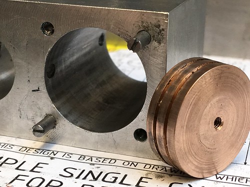 Simple single cylinder steam engine Simple single cylinder steam engine by GL5Keith1500, on Flickr This Is the second piston rod. The first one was under on length and consequently couldn’t be used. However it allowed me to get the length just right.  Simple single cylinder steam engine Simple single cylinder steam engine by GL5Keith1500, on Flickr |
|
|
|
Post by keith1500 on Mar 3, 2020 17:38:03 GMT
As mentioned above the length of the piston rod was found such that the piston would be set to the middle of the bore. This I figured would occur if the gap measured below the piston would be equal to that measured at the top. In the background is the car body rubbing compound. I guess T-cut would be ok too?  Simple single cylinder steam engine Simple single cylinder steam engine by GL5Keith1500, on Flickr In measuring the top it interesting to see how much of the steam port is covered by the piston.  Simple single cylinder steam engine Simple single cylinder steam engine by GL5Keith1500, on Flickr |
|
jasonb
Elder Statesman
Posts: 1,209
|
Post by jasonb on Mar 3, 2020 18:34:14 GMT
Does look like you have drilled the holes a bit further in from the end than Julius shows, the edge of the hole should touch the edge of the cylinder bore. All is not lost it is quite common to mill a notch at the end of the steam passage to allow easy flow into the cylinder, may also need to put a notchinto the spigots on the cylinder covers too. 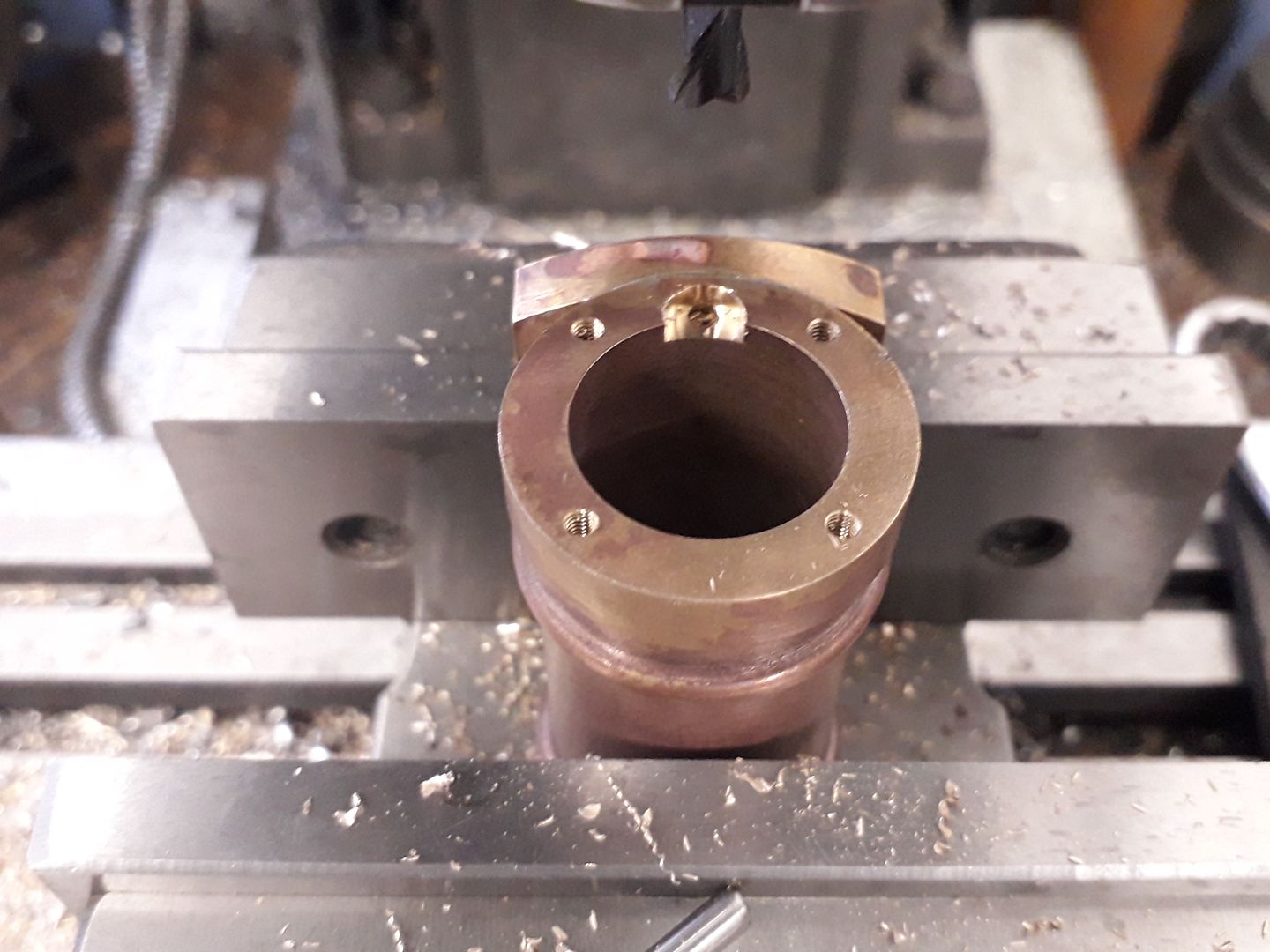  |
|
|
|
Post by keith1500 on Mar 4, 2020 18:01:39 GMT
I did think it odd at the time that the steam port should be so close to edge of the cylinder bore when the cover protruded 1 mm into the cylinder which would partially obscure the port. I didn’t expect the piston to cover quite so much when at the end of its travel. I think the piston could have been reduced from 8mm thick to 7mm.
Nevertheless I am not inclined to make an changes yet.
|
|


