|
|
Post by davewoo on Jun 27, 2021 11:26:45 GMT
Some lovely fabrication work Malcolm, this is going to be a very impressive locomotive indeed and your postings are inspiring, keep up the good work!.
Dave
I was pleased to read that I'n not the only one who takes a break and does something different on the engine when it gets a bit repetitive!
|
|
mbrown
Elder Statesman
  
Posts: 1,793
|
Post by mbrown on Jun 27, 2021 17:27:50 GMT
Many thanks for the kind comments Dave! It is always good to get feedback from within the "profession".
And yes, the whole point is that this hobby ought to be enjoyable - so I often find that I make the various "blobs and gadgets" early on and leave some of the basics until I get around to them. I especially enjoy making boiler fittings, but haven't got the arrangement of the boiler, cab, etc. in my head yet.
Best wishes
Malcolm
|
|
mbrown
Elder Statesman
  
Posts: 1,793
|
Post by mbrown on Jun 27, 2021 17:37:03 GMT
Blast pipe, Cap and BlowerOn the principle of "I've started so I'll finish" I decided to do some more of the exhaust arrangements. Here is the blast pipe cap and blower jets - I didn't take pictures while it was being made as it is entirely conventional and made from an odd end of 1" bronze and a short length of 1" dia brass tube. The jets are from 8 BA brass hex, threaded 6 BA to screw into the the blast pipe cap and with a No.78 jet. This is exactly what I used on the Burma Mines loco and it works very well indeed. The blower nozzles are inclined inward slightly so that the jets coincide at about the choke of the petticoat. The blast pipe itself is a length of 1/2" brass rod, drilled through at 9 mm and threaded for the cap and the locknut.  IMG_20210627_174854 IMG_20210627_174854 by malcolm brown, on Flickr And here it is in place in the smokebox. It is sitting too high at present as the socket for the blastpipe needs tapping a bit deeper. But that can wait until I put the whole lot together when more of the smokebox is completed. 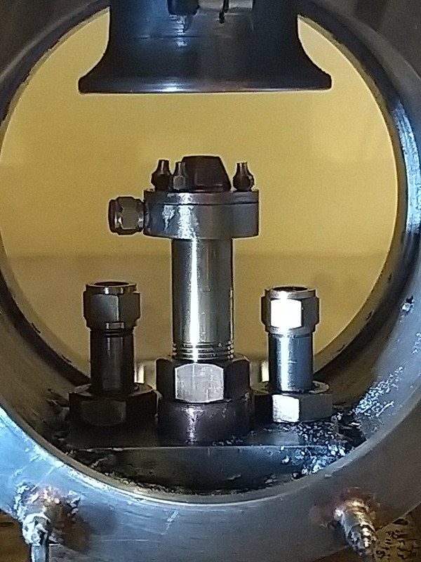 IMG_20210627_181757 IMG_20210627_181757 by malcolm brown, on Flickr I will see if I can brace myself during the week to get on with the spring gear next weekend! Malcolm
|
|
stevep
Elder Statesman
  
Posts: 1,073
|
Post by stevep on Jun 27, 2021 17:52:55 GMT
I agree with you Malcolm. I had a very similar arrangement on my Stanier, and it worked a treat.
|
|
mbrown
Elder Statesman
  
Posts: 1,793
|
Post by mbrown on Jul 10, 2021 17:03:36 GMT
Fixing the wheels and axlesToday's job, in between work commitments, has been assembling the wheels and axles. As noted in an earlier post, the axles are lengths of 1/2" PG BMS and the wheels are kept at the correct back to back distance by sleeves of steel tube. The sleeves and the wheels are Loctited onto the axle itself. Here are the various components. You can see the hole in the back of the wheel for a 4 BA grub screw. Once the Loctite has cured, a dimple will be cut in the axle and the grub screw will bite into the axle and be a guard against shock loadings that might, conceivably, break the Loctite seal. By using a grub screw, the circular stresses which build between the axle and the wheel as the Loctite cures, shouldn't be broken, which a longitudinal key would do. I got this idea from Don Young after he had reported a Loctited wheel on a 5"g Hunslet (which has no shoulders on the axle) came loose. I doubt if I would do it this way on a larger model, but in this scale it has worked well on two of my previous locos. 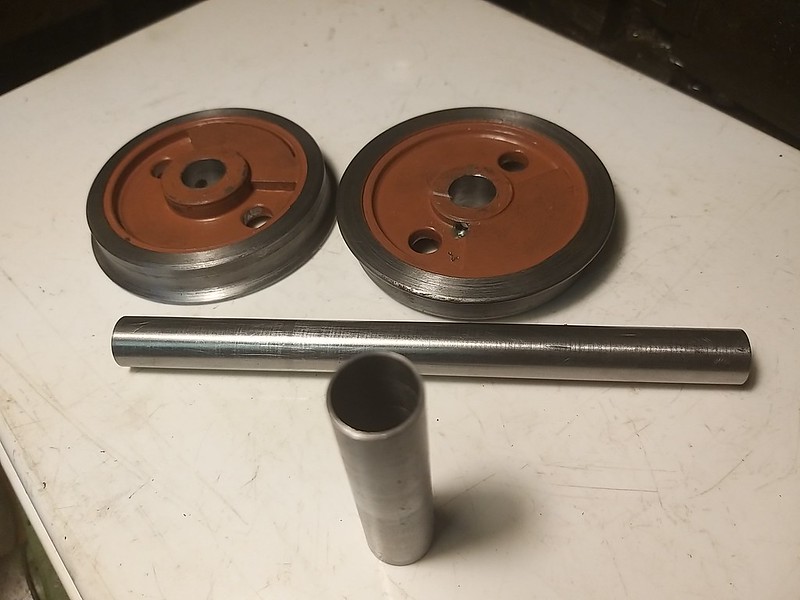 IMG_20210710_170741 IMG_20210710_170741 by malcolm brown, on Flickr The first job was to fix the spacer tubes precisely in the middle of the axle. To do this, I measured the length of the axle and the length of the spacer with the digital vernier, and divided the difference by two. Setting the vernier at the precise measurement, I then ran the sleeve onto the axle, after smearing it with Loctite, using the vernier depth gauge to get it exactly the right distance from the axle end.  IMG_20210710_171008 IMG_20210710_171008 by malcolm brown, on Flickr When that had set, one wheel was then Loctited in place. Although the crankpins are on the flycranks and not in the wheels, the wheels still need quartering reasonably accurately to ensure the balance weights are in phase. For this, I used the fact that the holes in the wheel centres are at 180 degrees and were drilled on coordinates in the mill. Two plates from hard aluminium were drilled for the axles and fitted with two stubs to fit nicely in the holes in the wheels and at 90 degrees to each other. (the stubs are held in place with neat brass cap screws simply because I had them to hand!) The numerous other holes in the plates were pre-existing - the plates were cut from a redundant foot plate from a racing eight, thrown out by my rowing club.... The axles holes are set at a precise distance from the long edge. 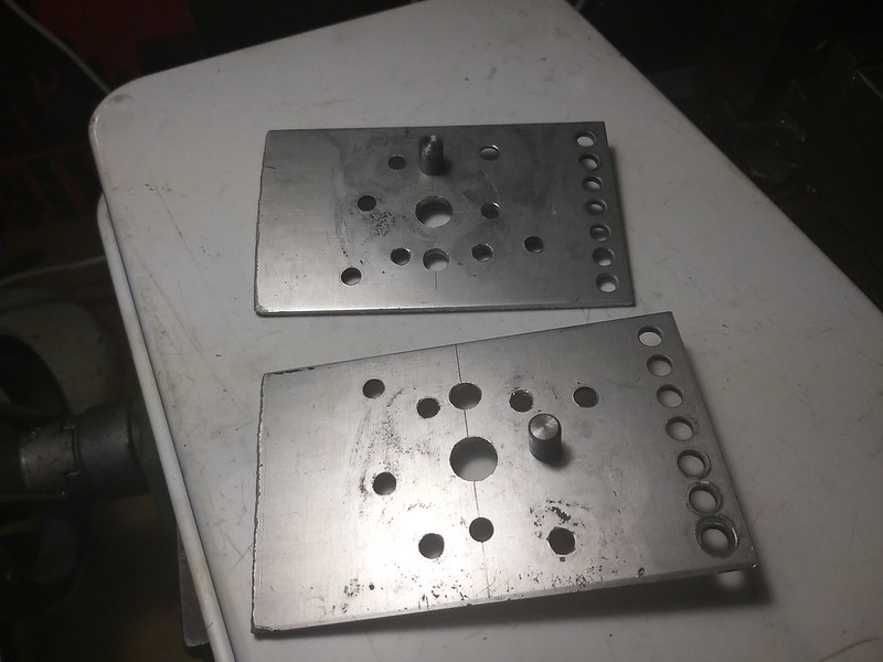 IMG_20210710_171413 IMG_20210710_171413 by malcolm brown, on Flickr The second wheel was then fitted in place and, before the Loctite went off, the whole assembly was placed between the plates and sat on the mill table to keep everything aligned. When the Loctite has thoroughly cured, the dimples can be made for the grub screws and the wheel sets are then ready to go into the frames.  IMG_20210710_165825 IMG_20210710_165825 by malcolm brown, on Flickr It beats Wimbledon! Malcolm
|
|
|
|
Post by suctionhose on Aug 4, 2021 12:22:35 GMT
Hello Malcolm,
I see your Burma Mines loco on the 'what have I done today' thread. It is a really lovely engine amoung the narrow gauge types. Not much like the appearance of the ones shown on Youtube still in service!
I noticed all the operational engines had vertical sides to the firboxes and different tenders. Did you build yours from Bagnall drawing archives or how else? It's a lovely model in every way...
|
|
mbrown
Elder Statesman
  
Posts: 1,793
|
Post by mbrown on Aug 4, 2021 14:56:21 GMT
Many thanks Ross - much appreciated.
She's the most complex model I have built to date and seems to go very well - or, at least, will do when I have got both injectors to do their stuff and have mastered control of the fire (she has a very big grate and a combustion chamber. The ashpan has front and back dampers - shutting them both makes the fire die down, but opening them both makes too much steam to control. I am still experimenting to find a happy medium).
The prototype is by North British, not Bagnall. North British supplied three 0-6-0s to this design in 1908 and a further three, to a modified design capable of converting to 2'6" gauge, in 1915. The 1908 batch had all gone by 1930 but at least one of the 1915 batch lasted into the '70s. The difference to the frames made me choose the 1908 design - these had a big casting joining the front and rear frames, the latter splayed out to accommodate the firebox. The 1915 ones had very complicated joggles in the frame which I didn't think I could reproduce. I did, however, incorporate two features of the 1915 batch, rather anachronistically. The 1908 ones had a tiny reversing lever which was tucked into the corner of the cab and quite inaccessible to out-of-scale finger, so I modelled the screw reverser as on the later engines. Similarly, I gave her a pull-out regulator like the 1915 locos, for the simple reason that I fancied a change from my usual rotary regulator!
The loco is built from a very comprehensive GA drawing from the NBL archive at Glasgow University, and a pipe diagram of the 1915 locos. Only one photo was available - the works photo taken before delivery. I tried all sorts of sources but couldn't find any others, although I did find a couple of rather poor shots of the 1915 locos which didn't tell me anything new. Then just after I had finished painting (in grey like the works photo) a friend found two shots of her a few months after delivery - and very useful they would have been as they showed the loco on its side after an accident! They revealed that the disc wheels had holes in them which weren't shown on the drawing (but you can't normally see the wheels so it doesn't matter much) and the paint scheme was almost certainly dark green with lining exactly as on the works drawing but probably in red and black.
One does get a bit obsessive about fidelity to prototype after a while... !
The Bagnall tender loco that is still in existence on the BMR is a 2-6-2 built in the 1920s. I did consider one, if I could have got the drawings (I think they do exist), but the trailing truck would have made access to the grate tricky, whereas, on mine, the grate and ashpan just drop free.
Thanks again for the nice comments - your traction engine is an inspiration!
Best wishes
Malcolm
|
|
mbrown
Elder Statesman
  
Posts: 1,793
|
Post by mbrown on Sept 4, 2021 18:45:12 GMT
Spring GearIt has been a while since I posted. After the 2.5" Gauge rally at Little Hey a month ago, I have spent some time doing odd jobs on the Burma Mines loco (like making the second gauge glass protector which I never got around to earlier) and then holidays intervened - although a fortnight of driving on the Talyllyn gave me a good fix of steam. I was also at the point with 99 3462 where the only way ahead involved a lot of rather mundane repetition work which I wasn't really motivated to do. Anyway, last weekend and this, I knuckled down to it on the basis that, by approaching it systematically, all the bits will get done. So here is the fruit of the recent labour - 16 spring pins, each with their collar to bear on the end of the spring and their nut (3mm fine thread, so home made) and 8 spring buckles. Now I have to solder the ends onto the top spring leaves (16 ends), assemble the springs in the buckles and erect it all. These bits are all exactly the same as on the tender, but twice the number of course.  IMG_20210904_174909 IMG_20210904_174909 by malcolm brown, on Flickr When the spring gear is done, I might do the fly cranks, although I can't fit the driving crankpin until I have designed the valve gear and decided the throw of the return crank. Now that my boiler design has been signed off, I am really itching to get down to some copper-bashing as I love boiler making. But maybe a bit more progress with the chassis first would be sensible or I will forget which bits still need revisiting... Hoping to attend the 2.5"g rally at Rugby next weekend, all being well. Best wishes Malcolm
|
|
mbrown
Elder Statesman
  
Posts: 1,793
|
Post by mbrown on Sept 11, 2021 18:17:47 GMT
Loco SpringsAnother couple of afternoons in the workshop and I have completed the eight leaf springs for the loco. This took a lot longer than I expected. Each bulbous end had to be soldered on separately with the rest of the top leaf jammed into a large potato. This is as recommended by Don Young and works well to ensure the leaf doesn't lose its temper. What it did to my own temper is another matter as it was hard to stop the solder taking on the bits used to hold the half-round wire in place. A cutting disc in the Dremel sorted that out. The buckles had to be filed out very carefully so that the top leaf didn't bear only at the corners, and yet the leaves needed to be a close fit in the buckle. Getting them to line up, so that the 1/16" hole through the leaves lined up with each other and with the hole through the buckle was a Chinese puzzle - some leaves slid easily against each other, others tended to lock together. Using a small drill bit to "feel" for each hole helped. Anyway, we got there. Next job is to make the last eight pivot pins for the spring hangers and erect the whole caboodle, along with the equalising beams etc.  IMG_20210911_181133 IMG_20210911_181133 by malcolm brown, on Flickr When that is done, I am minded to start in the boiler I already have the barrel and most of the tubes and this weekend I drew up a cutting list for all the plates. The order will go in next week. With luck, my boiler work will be taking place just as the evenings draw in which means the light should be just right for silver soldering. Off to the 2.5"G Rally at Rugby tomorrow, but more from the workshop soon, I hope. Malcolm
|
|
mbrown
Elder Statesman
  
Posts: 1,793
|
Post by mbrown on Sept 18, 2021 17:12:25 GMT
Springing continued...Here are the springs and spring hangers erected, although not adjusted as yet. The pintles on the spring buckles are a tad too big to engage with the pockets in the tops of the axleboxes, but I left the pockets a bit small deliberately so that they could be opened out to suit, so that can be amended easily.  IMG_20210918_172738 IMG_20210918_172738 by malcolm brown, on Flickr There was a lot of work in them there springs and all the associated bits.... But they look the part and are suitably flexible yet fairly stiff, which is what I wanted for a relatively short wheelbase and a top heavy loco.  IMG_20210918_172750 IMG_20210918_172750 by malcolm brown, on Flickr The prototype has pieces of bent plate as a kind of spring retainer - here are the ones on the tender and the loco has similar ones. I am not sure if they are original or an afterthought - they are not all identical and have the appearance of being bent up individually. I imagine they have proved necessary in full size but I am not sure whether to reproduce them or not - they would be quite flimsy in model size, and probably a nuisance when erecting or adjusting the springs.  DSC00503 DSC00503 by malcolm brown, on Flickr Anyway, that's another milestone reached. The copper sheet for my boiler arrived yesterday, the tubes are already in stock, and so I need to get the chassis into one piece before turning over the workshop to boiler making. That may occupy a few days, then I need to carve out my formers and start some copper-bashing.... Malcolm
|
|
mbrown
Elder Statesman
  
Posts: 1,793
|
Post by mbrown on Oct 9, 2021 17:42:50 GMT
Boiler formersI haven't had much workshop time in recent weeks and what little I had was spent trying to trace the leak in the vacuum brake system on my driving truck. It turned out to be a split in a rubber connecting tube which only opened when the brake cylinder pivoted on its trunnions, so as you can imagine, it took a long time to find (and about 30 seconds to fix....). Anyway, a little further progress on 99 3462 today. All the copper for the boiler is now to hand so I decided to make the flanging formers. I have always made my formers in Tufnol - it is easy to work, light and very resilient. Bought new, it is quite expensive, but over the years I have accumulated quite a lot of suitable Tufnol sheet that has been thrown out by one establishment or another. As the boiler barrel on 99 3462 is 4" diameter, the same as the Burma Mines loco, I can use the same formers for the front tubeplate and for the outward flange on the throatplate. I had a piece of 5/8" Tufnol which just nicely made the formers for the firebox plates and for the throatplate and back plate of the boiler shell. The latter has an 8 mm radius put on the edge as I like the outer plates to be well-radiused like a full-size boiler (a bit of a nonsense in this case as 99 3462 has the firebox cladding made with sharp right angle corners - but good radii on the boiler itself are still best practice). I did wonder about saving material by making the firebox flanged plates by cutting down the one from the Burma Mines loco, but one never knows if a new boiler might have to be made one day. I keep all my formers just in case. The current boiler will be my fourth and should be very straightforward as the firebox is round topped with parallel sides and vertical backplate and throatplate, in contrast to the Burma Mines loco which had a Belpaire firebox, sloping throat and back plates and a combustion chamber. I suspect, though that 99 3462 will not steam as freely as the boiler proportions don't look so good...I'll find out in a few years.... Anyway, here are the flanging blocks.  IMG_20211009_163631 IMG_20211009_163631 by malcolm brown, on Flickr Firebox plates to the left upper, backhead and throatplate below it, tubeplate and the former for the throatplate outer flange to the right. I trepanned the tubeplate former out of the sheet which then got used to do the throatplate outer flange. Not sure when I shall start copper-bashing - I am away again for the a few weeks - but I am looking forward to it. Malcolm
|
|
mbrown
Elder Statesman
  
Posts: 1,793
|
Post by mbrown on Oct 10, 2021 17:25:10 GMT
Boiler BarrelI bought a 12" length of 4" dia x 2.5 mm copper tube for the boiler barrel some time ago before I had finished designing the boiler. As it turns out, I need it to be 10.75" long. Here is my set-up for facing off the ends and parting off the redundant length. Two discs of MDF mounted on a 10 mm length of studding. The disc nearest the chuck is stepped to fit into the barrel - the other is a tight push fit and can be set as far down the barrel as one wants.  IMG_20211010_165820 IMG_20211010_165820 by malcolm brown, on Flickr Here is the barrel mounted on it. The chuck jaws just grip the end to give a positive drive. Having faced one end, the barrel was reversed and cut to length using a 1/16" parting tool.  IMG_20211010_170914 IMG_20211010_170914 by malcolm brown, on Flickr While it was in the lathe, I put the dividing fixture onto the mandrel and scribed a line along the whole of the top of the barrel to mark the top centre, then shorter lines at 90 degrees for the clack bushes. I had time after that to make a start on the numerous bushes that will eventually go into the boiler, including the dome bush with its take-offs for auxiliaries at each side. I need some high melting point silver solder before I can finish that off. It will be a few weeks before I am back in the workshop, but it is nice to have made a bit of progress. Malcolm
|
|
mbrown
Elder Statesman
  
Posts: 1,793
|
Post by mbrown on Oct 24, 2021 16:47:39 GMT
Boiler bushes etc.
Back in the workshop for a few hours today and have made some progress with the bits for the boiler. The main item is the dome base with the outlets for steam fittings either side as per the prototype. Because of these outlets, it couldn't be made from the usual casting, so a large gunmetal bush was machined to form the upright part, two bushes made up for the side outlets, and a square of 3 mm copper bent to fit over the boiler barrel and bored to fit. The whole lot was silver soldered together with high melting point solder, then the base was rounded off. I started this in the lathe, but realised the tool would have fouled the side bushes, so most of the rounding off was done with files.  IMG_20211024_172312 IMG_20211024_172312 by malcolm brown, on Flickr Also completed are a number of bushes for the boiler, including the one for the manifold which has an internal pipe leading to the dome, and the oval fire hole ring. Some of the bushes are quite large outside diameter compared to the threaded hole, and they stand out more than is usual from the boiler. This is because the fittings on these bushes are going to have dummy flanges with studs and nuts and they need to come flush with the cladding, or just proud of it. A few more bushes to do, then I must start flanging the plates. Malcolm |
|
mbrown
Elder Statesman
  
Posts: 1,793
|
Post by mbrown on Oct 26, 2021 16:56:21 GMT
Silver Solder query
I have just bought a batch of silver solder for the boiler from our friends at CupAlloys and it is, of course, the cadmium=-free stuff. However, I have just discovered a stash of Easyflo No.2 which I had forgotten I had.
Neither stock is enough to complete the boiler on its own - so does anyone have any experience of mixing the two? According to the label, the low melting point cadmium-free solder melts at a slightly higher temperature to Easyflo No.2 but there isn't a lot in it.
Is there any reason not to use both solders on the one boiler, bearing in mind that all my soldering is done out of doors with plenty of fresh airflow?
Thoughts welcome.
Malcolm
|
|
don9f
Statesman
  Les Warnett 9F, Martin Evans “Jinty”, a part built “Austin 7” and now a part built Springbok B1.
Posts: 961 
|
Post by don9f on Oct 26, 2021 22:35:19 GMT
Hi Malcolm, I have used Silverflo 55 (630 deg.) & Easyflo No2 (617 deg.) together with no problems. After reading your question, I had a quick look online for any reference to this and a posting near the bottom of this page is of relevance, stating that they are fully compatible..... Cheers Don |
|
|
|
Post by ettingtonliam on Oct 27, 2021 1:29:48 GMT
Just in case it becomes an issue in the future, it might be a good idea to keep a note of which solder you used and where in the boiler you used it.
|
|
|
|
Post by Roger on Oct 27, 2021 7:20:50 GMT
Just in case it becomes an issue in the future, it might be a good idea to keep a note of which solder you used and where in the boiler you used it. You won't need to make a note, the Cadmium solder is much more Yellow and it forms fillets with a bigger radius. I believe that the Cadmium was added to make it thicker so it would fill gaps easier. My backhead had a few places that didn't want to fill, and Cadmium solder fixed that issue. |
|
mbrown
Elder Statesman
  
Posts: 1,793
|
Post by mbrown on Oct 27, 2021 7:22:57 GMT
Many thanks both. I shall proceed with both and if any problems do arise, will report them on this thread.
Best wishes
Malcolm
|
|
uuu
Elder Statesman
   your message here...
Posts: 2,860
Member is Online
|
Post by uuu on Oct 27, 2021 15:48:14 GMT
You won't need to make a note, the Cadmium solder is much more Yellow and it forms fillets with a bigger radius. I believe that the Cadmium was added to make it thicker so it would fill gaps easier. My backhead had a few places that didn't want to fill, and Cadmium solder fixed that issue. That's been my experience, too. The new stuff will penetrate, even if the parts are lightly clamped, where the cadmium stuff, being thicker, tends to work better with a small gap. Wilf |
|
mbrown
Elder Statesman
  
Posts: 1,793
|
Post by mbrown on Oct 31, 2021 18:50:33 GMT
Flanged PlatesThis afternoon saw all the flanged plates finished, apart from trimming them to length and drilling all the holes. I started with the firebox tubeplate and door plate, mainly because they have the tightest radii - in the end, they took four annealings, and so did all the other plates. Here are pictures of the plate after each round of annealing and shaping. The first round doesn't seem to get very far: 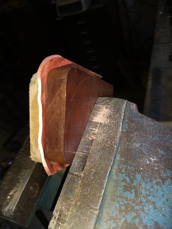 IMG_20211031_135515 IMG_20211031_135515 by malcolm brown, on Flickr ... after the second: 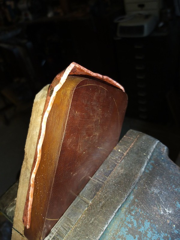 IMG_20211031_140128 IMG_20211031_140128 by malcolm brown, on Flickr ... by the third, the copper is moving more freely ...  IMG_20211031_141030 IMG_20211031_141030 by malcolm brown, on Flickr ... and the fourth and final round of hammering.  IMG_20211031_142603 IMG_20211031_142603 by malcolm brown, on Flickr I try to concentrate first on the corners, taking them down slowly so that the copper doesn't "pucker" and crease, then the sides come down nicely to fit the former. I used the boxwood bossing mallet for most of the job, then did the final tapping down to the former with the planishing hammer. The backhead, with its gentler radii, interestingly, also needed four annealings, as did the smokebox tubeplate. The throatplate, being double flanged, took a lot longer. I started by making the outward flange against a former made for the Burma Mines loco where the outward facing flange goes through 360 degrees. Making a flange for only half the diameter was harder as the "ears" tended to pull inwards, as is visible below, despite clamping the copper between the former and the backing plate with G clamps. As there was no space to wield a hammer, I used a length of 1" BMS bar as a hammer. The marks filed out easily enough later.  IMG_20211031_152334 IMG_20211031_152334 by malcolm brown, on Flickr Then I bolted a circular former to the backhead former and clamped the embryonic throatplate to it with a big Jubilee clip before flanging the sides onto the backhead former. To some extent, this pulled the ears back into line, but not enough. Fortunately, I had left plenty of material and the flanges cleaned up to size later.  IMG_20211031_153629 IMG_20211031_153629 by malcolm brown, on Flickr I turned the outer edge of the tubeplate to fit the boiler barrel and trimmed the flanges on the other plates by clamping them face downward on the mill table and using an end mill to level off the flanges. After cleaning up, here they are. 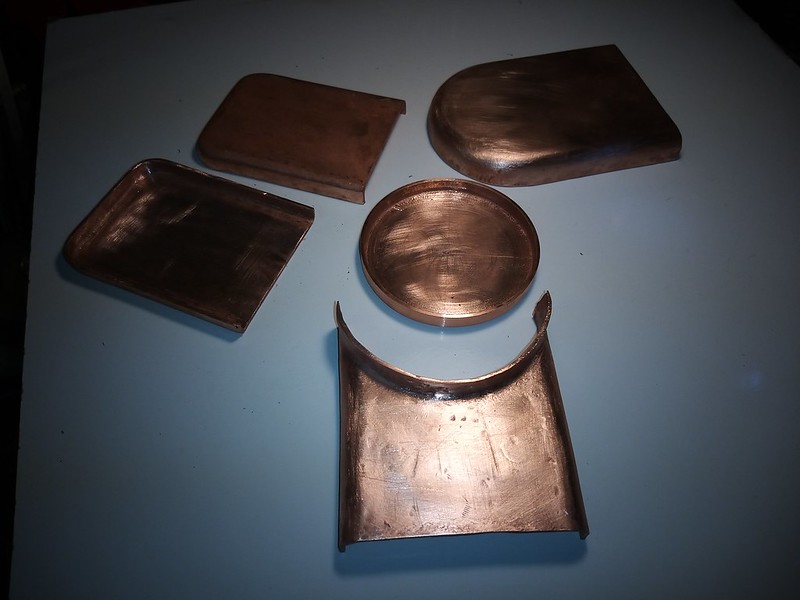 IMG_20211031_174502 IMG_20211031_174502 by malcolm brown, on Flickr The plates are all over-long at present, which will allow me to ensure that the bottom edges are truly square. There are a few annoying "dings" on the throatplate, reflecting the difficulty of holding it firmly for the two-way flanging process, but I am hoping that some are in the bit to be cut off and others won't show as they will be in the area of stay-heads when the boiler is finished. The great thing about boiler making is that you can make a lot of progress quite quickly! Best wishes Malcolm
|
|