|
|
Post by RGR 60130 on May 22, 2020 11:32:11 GMT
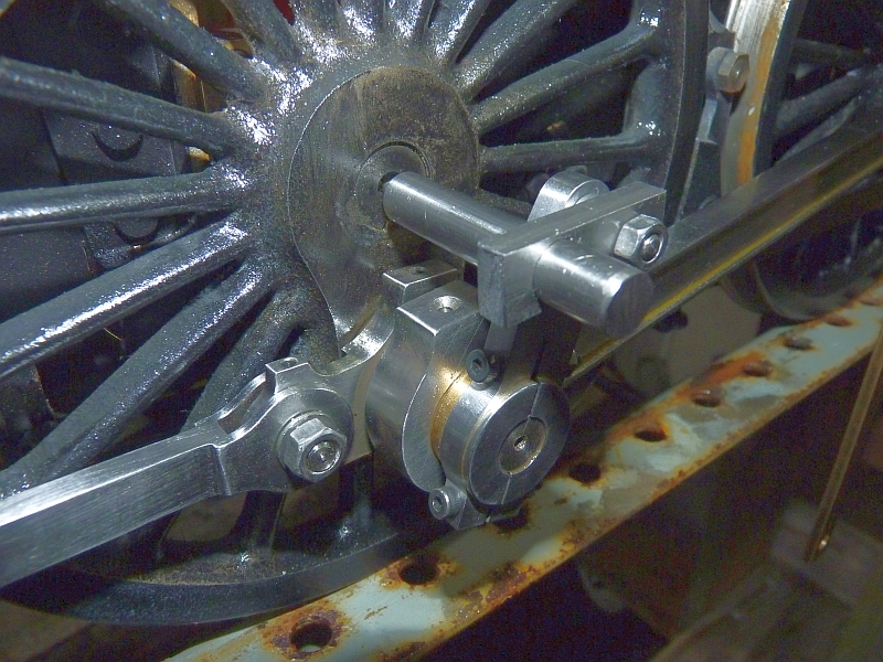
As drummed into forum members many times by Don Ashton, there is only one correct position for the return crank on a locomotive with Walschaerts valve gear and thus it doesn’t need to be adjustable. However, once you know the diameter of the pitch circle that the end of the return crank needs to describe, the question arises of how to set it accurately. This week I was asked if I would set a pair of cranks for a friend so I thought I’d take the opportunity to take some photos and do a little write-up which may help others. In the example that I am going to describe here, the end of the return crank needs to describe a pitch circle 1 ¾” in diameter; i.e. the centre of the business end of the return crank will be 7/8” from the centre of the axle. The hole in the end of the return crank is ¼” diameter.  BRC Drawing BRC Drawing by George Rossiter, on Flickr We now need to make two items. The first of these is a pin which will fit the ¼” hole in the end of the return crank. The second is a plug to fit in the wheel centre. The smaller end of the plug should be a nice close fit in the wheel centre. The larger end will be 1 ½” diameter. Why is this? Well we know the centre of the return crank hole needs to be 7/8” away from the centre of the axle. The ¼” pin on its own effectively accounts for 1/8” leaving another ¾” to be accommodated by the plug so 2 x ¾” = 1 ½” diameter. The first photo shows the wheel, the return crank on the crank pin, the pin and the plug. Note that the paint has been carefully scraped away around the area of the crank pin where the coupling rod bush will rub and the shoulder of the crank pin will sit.  BRC01 BRC01 by George Rossiter, on Flickr The second photo shows the plug and the pin in position ready to glue in the crank pin with Loctite. My preferred cleaner is cellulose thinners. Keep cleaning the crank pin and hole until the cleaning cloth remains spotless.  BRC02 BRC02 by George Rossiter, on Flickr The third and fourth photos shows the crank pin in position with the brass pin touching the brass plug. Wipe off any excess Loctite and leave it to cure. 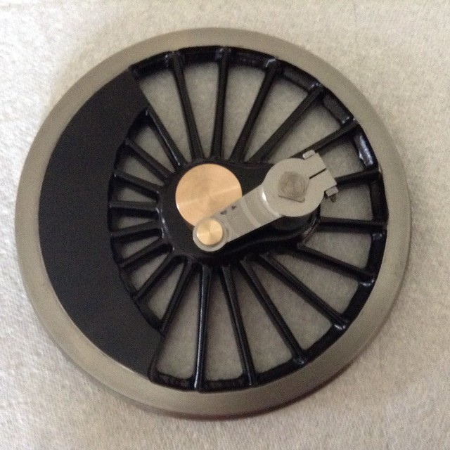 BRC03 BRC03 by George Rossiter, on Flickr 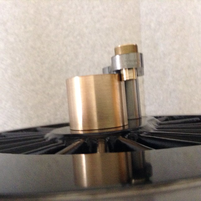 BRC04 BRC04 by George Rossiter, on Flickr In picture 5 the pin and plug have been removed and the return crank is set in its correct position. 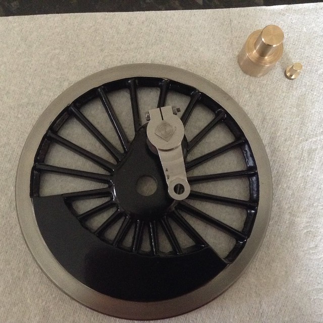 BRC05 BRC05 by George Rossiter, on Flickr Many people will be happy to leave things as they are at this point while many others will prefer to do a belt and braces job with a grub screw. I’ll cover this in the next post. |
|
|
|
Post by RGR 60130 on May 22, 2020 11:33:54 GMT
For those who wish to use a grub screw as part of their crank pin retaining, this is how I do it. You could opt to clamp the wheel but I prefer to hold the job by the crank pin using a split block which can be clamped in a milling or drilling vice as below. 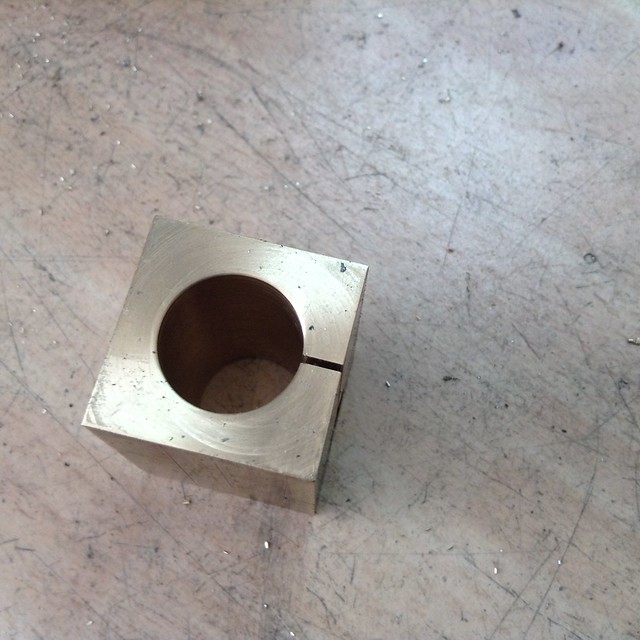 BRC06 BRC06 by George Rossiter, on Flickr My preference is to use a 4BA grub screw which is ¼” long. The required tapping size is 3mm so I used a 3mm centre cutting slot drill to drill the hole. With an ordinary drill there is a possibility of the drill wandering off into the cast iron whereas the slot drill will stay on course. There was enough thickness to the wheel and enough flutes on the cutter to let me drill down 3/8”. Yes, I am using a Jacobs drill chuck and not a milling chuck because this is essentially a drilling operation and the slot drill isn’t experiencing any significant side loads.  BRC07 BRC07 by George Rossiter, on Flickr Without moving the job I replaced the slot drill with a 4BA taper tap and got the threads started. You may only get a couple of threads before the tap bottoms out in the hole – take care.  BRC08 BRC08 by George Rossiter, on Flickr I then removed the job from the vice and tipped out all the accumulated swarf from the hole before replacing it in the vice again. Using a tap wrench I then alternated between a second cut tap and a plug tap to get the required depth of thread. Nudging the tap forward and backing it off fully seems to be the way to go based on experience.  BRC09 BRC09 by George Rossiter, on Flickr With care you should end up with a tapped hole that allows the grub screw to be screwed in until its just below the surface of the wheel.  BRC10 BRC10 by George Rossiter, on Flickr Finally make sure you produce a pair rather than two the same.  BRC11 BRC11 by George Rossiter, on Flickr |
|
uuu
Elder Statesman
   your message here...
Posts: 2,866
|
Post by uuu on May 22, 2020 11:50:15 GMT
You can use the same procedure if the wheel is already on the locomotive. Perhaps because some "expert" has decided to cure the club loco's poor running by adjusting its return crank. Instead of the gauge fitting into the wheel bore, it can have a spike that fits into the centre of the axle.
Wilf
|
|
|
|
Post by delaplume on May 22, 2020 12:04:27 GMT
What an excellent article !!...........This should be mandatory reading for anyone building / overhauling a Walshaerts system...... Good, clear supporting photos as well makes it a joy to read...I particularly liked the mathematical explanation as well.....Many thanks !!
|
|
|
|
Post by Deleted on May 22, 2020 12:17:33 GMT
Nice article Reg, Wilf that's how I did mine and how Don Young described it is done in full size. Don did also describe how to do it Reg's way but I had already fitted the wheels to axles so used the second method as you described. The other thing to remember is that the eccentric pin chases the crank pin for piston valves and correct me if I'm wrong, visa versa for slide valves. Looking at Reg's drawing and assuming it's piston valve the wheel shown will be for the left-hand side. I hope...  Pete EDIT: Thinking about piston or slide valves, is it that or is it inside vs outside admission? |
|
|
|
Post by John Baguley on May 22, 2020 12:28:51 GMT
Yes, I used Wilf's method as well for the Brit chassis that I rebuilt. Much better to use a jig than faff around using trial and error!
Just a bit of bar with two holes spaced to the radius of the return crank circle and a length of bar with a 60° point on the end to locate in the centre of the axle.
John
|
|
mbrown
Elder Statesman
  
Posts: 1,798
|
Post by mbrown on May 22, 2020 12:47:45 GMT
Agreed - a most helpful post. Thanks Reg.
Pete - what you describe is true if the gear is set for the lower part of the expansion link to be used for forward gear and the top for reverse, which is the more usual arrangeemnt. On some locos, such as the SR Moguls, the loco goes forward when the die block is at the top of the expansion link, and in that case, the return crank is set to the opposite position (i.e. ahead of the crankpin for piston valves).
Malcolm
|
|
|
|
Post by delaplume on May 22, 2020 13:00:51 GMT
Alas, not every model comes with the wheel centers in.......I've an oldish Simplex in my works at the moment that is "Sans Centre" in all 6 positions...Horrors !!
Peter,
Piston valves are usually built as inside admission..(Noticeable variance being Bullied's pacifics ).....
Slide valves are ( in general ) outside admission......There is a difference in design when you look at where the Radius rod and Combinaton lever are connected........An easy one to spot is LBSC's Princess Marina where the cylinder looks like Piston valves are fitted but a glance at the Radius rod / Combination lever pivot set-up tells you it's an outside admission -- in this case slide valve...
|
|
stevep
Elder Statesman
  
Posts: 1,073
|
Post by stevep on May 22, 2020 14:57:39 GMT
I think that's an excellent description of how to set the return crank.
I would add one note of caution, in that you are setting it to a defined radius - which comes from the design. A quick glance may suggest that the return crank is the hypotenuse of a right-angled triangle with the other two sides being the line between the axle centre and the crankpin centre, and the one between the axle centre and the return crank pin centre.
On most designs, the eccentric rod is at an angle to the centre line of the valve gear - so the triangle is NOT right-angled. (I realise it can be, not not normally). So this method is perfect if you have all the dimensions.
|
|
uuu
Elder Statesman
   your message here...
Posts: 2,866
|
Post by uuu on May 22, 2020 16:55:53 GMT
I do like your idea of setting everything up with the wheel off. It seems a more certain process, and easier on the flat. I may do Jessie this way, and drill through for a taper pin, so that the eccentric crank can be removed for fitting the coupling rod.
Wilf
|
|
|
|
Post by jo479 on May 22, 2020 17:53:25 GMT
Excellent description, I used M Evans method on Simplex with an adjustable rod, your method is easier and more accurate, thank you
|
|
|
|
Post by Roger on May 22, 2020 19:14:52 GMT
Alas, not every model comes with the wheel centers in.......I've an oldish Simplex in my works at the moment that is "Sans Centre" in all 6 positions...Horrors !! Peter, Piston valves are usually built as inside admission..(Noticeable variance being Bullied's pacifics )..... Slide valves are ( in general ) outside admission......There is a difference in design when you look at where the Radius rod and Combinaton lever are connected........An easy one to spot is LBSC's Princess Marina where the cylinder looks like Piston valves are fitted but a glance at the Radius rod / Combination lever pivot set-up tells you it's an outside admission -- in this case slide valve... Hi Alan, There's nothing to stop you setting them up in the lathe and put the centres in... |
|
jma1009
Elder Statesman
  
Posts: 5,926
|
Post by jma1009 on May 22, 2020 19:30:40 GMT
Hi Reg,
As Steve hinted, your method presupposes that the centres of the return crank length are absolutely correct for the valve gear design details.
The test is whether for FDC and BDC and with the expansion link in a position where no movement is imparted to it by the radius rod moved up and down you get the same length for the eccentric rod centres. If not, the valve events will be unequal.
Cheers,
Julian
|
|
|
|
Post by delaplume on May 22, 2020 20:33:04 GMT
Alas, not every model comes with the wheel centers in.......I've an oldish Simplex in my works at the moment that is "Sans Centre" in all 6 positions...Horrors !! Peter, Piston valves are usually built as inside admission..(Noticeable variance being Bullied's pacifics )..... Slide valves are ( in general ) outside admission......There is a difference in design when you look at where the Radius rod and Combinaton lever are connected........An easy one to spot is LBSC's Princess Marina where the cylinder looks like Piston valves are fitted but a glance at the Radius rod / Combination lever pivot set-up tells you it's an outside admission -- in this case slide valve... Hi Alan, There's nothing to stop you setting them up in the lathe and put the centres in... Hello Roger and thanks for the idea but I've already done that, plus put some cross-drillings in the axle for easy access lubrication......As soon as the Water Bowser project is finished I'll get this loco back on it's wheels..........It's still "in ticket" but the onset of the virus meant I've now given preference to the bowser as this will be of more immediate use... |
|
|
|
Post by silverfox on May 22, 2020 20:55:07 GMT
Roger
If you have not been given the PCD, how do you calculate it and what dimensions do you need?
Ron
|
|
don9f
Statesman
  Les Warnett 9F, Martin Evans “Jinty”, a part built “Austin 7” and now a part built Springbok B1.
Posts: 961 
|
Post by don9f on May 22, 2020 21:11:50 GMT
Hi Reg, an excellent guide!
Cheers Don
|
|
|
|
Post by Roger on May 22, 2020 21:31:31 GMT
Roger If you have not been given the PCD, how do you calculate it and what dimensions do you need? Ron I have no idea without seeing a drawing. With a drawing, I'd put it into a CAD program to get any required dimensions that I needed. |
|
|
|
Post by silverfox on May 22, 2020 21:35:26 GMT
Roger
what do you need?
|
|
|
|
Post by Deleted on May 22, 2020 21:42:36 GMT
Roger If you have not been given the PCD, how do you calculate it and what dimensions do you need? Ron I have no idea without seeing a drawing. With a drawing, I'd put it into a CAD program to get any required dimensions that I needed. I'm not sure that CAD can help as without the PCD or the angle you are missing to much info to draw it. As Stevep pointed out the return crank is not at 90 degrees for most, can't say for 'all' as I don't know enough about other designs. Certainly for Doncaster the angle ia less than 90. |
|
dscott
Elder Statesman
  
Posts: 2,440
|
Post by dscott on May 23, 2020 1:20:07 GMT
I have not quite got past MOTION BRACKET with Jessie Substitute (Toaster) for Last of The Summer Wine fans!
Lovely inspirational information Reg and Thank You as Jessie seems to have this valve gear.
I will have to be a WHEELS ON BOY!!!
1 and 1/16" circle and something in 1. 475" To work to. Up to now I have only made Stephensons valves.
There may be a rod held in the lathe and another thick washer like piece sat on the 1/4" crank.
Move it round until they meet and we are set. UUU and I have round ones not square.
Goes and consults the pile of drawings resident upon the Dining table.
Looks like a 3/8 rod held in the tailstock chuck with a center pip. and a 5/8 washer over the pin.
David and Lily.
|
|
 BRC Drawing by George Rossiter, on Flickr
 BRC01 by George Rossiter, on Flickr
 BRC02 by George Rossiter, on Flickr
 BRC03 by George Rossiter, on Flickr
 BRC04 by George Rossiter, on Flickr
 BRC05 by George Rossiter, on Flickr
 BRC Drawing by George Rossiter, on Flickr
 BRC01 by George Rossiter, on Flickr
 BRC02 by George Rossiter, on Flickr
 BRC03 by George Rossiter, on Flickr
 BRC04 by George Rossiter, on Flickr
 BRC05 by George Rossiter, on Flickr


