dscott
Elder Statesman

Posts: 2,438
|
Post by dscott on Jun 4, 2020 5:23:51 GMT
Also worthy of note are the series of articles in the 1970 Model Engineer of which I have borrowed copies from the Club at present.
WELL on Page 132 and 133 6 of FEB 1970 volume 136 number 3386 which should come up on any digital database!
There are 3 lovely photos showing Kens own model complete with a Wonderful Lubrication system all fed from one box on the footplate side. A One Shot system which also covers the axle pump. Again wonderful drawings.
Upon reading through the only other problem encountered with the model so be warned!!!!
Is that Bridget has worn out 2 sets of Superheaters.
Now judging by the the lovely YOUNG photo on page 129 he loved driving her so much so that a mileometer was fitted.
OH and one more thing... November 1966 a new chimney was fitted?
Possibly new draughting was tried and it worked.
David and Lily.
|
|
|
|
Post by Roger on Jun 4, 2020 8:44:47 GMT
Hi Gary, "The big trough full of oil on top of each axle box tends to collect all the ash dust and grit that's going (which is quite a lot on a steam loco) so heaven-knows-what can get carried down the oilway into the journal; or indeed block it, potentially." Agreed, an open trough is a bad idea, hence the close fitting covers I've made for mine with a smaller hole for filling them. The traditional place for the feed hole is on the axle centre line, and that does seem to work, even though it's in the place of highest pressure. However, I thought one in front and one behind the centre line would guarantee that the one on the less loaded side would always feed a little. Any oil present will cause the axle to rise slightly onto the thin wedge of oil, and the axle will tend to move downwards and to the back while it's running and loaded. It would be interesting to know how long a bearing would last without a felt pad, where the only supply is that little hole in the top. I imagine that wouldn't last long at all, since it would likely spend most of its life running nearly dry. The felt pad still needs to be replenished, so in my opinion a wick or reservoir system is preferable to a one time filling of the pad from say a drillway in the end of the axle. Hi Roger (and Wilf) Yes, in full size the felt pad was both a wick and a spreader, and had its feet in an oil reservoir. I must look up the story again, but I seem to recall that the plug for the reservoir had to be specially designed to prevent dyed-in-the-wool old timer enginemen from inserting worsted trimmings into it! I don't think the principle would transfer all that well to scaled models though. It is difficult to make 'trimmings' work in miniature, and I suspect a felt pad might be an unnecessary complication. Relative to full size, our bearings don't run hot, because liquids don't scale, and our bearings can retain a massively thick and sticky oil film in comparison. I think the average model loco bearing gets a squirt of oil at the start of running, which lasts until the next time the driver thinks of giving it another, which could be an hour later, or more. I don't think running dry is a particular issue, especially with modern extra-sticky oil (I use Chainsaw oil myself) It goes without saying that the main problem is getting the oil into the bearing in the first place, which isn't always as easy as it sounds. Logically Wilf's suggestion of feeding the oil to one side rather than the top of the bearing makes a lot of sense, as would oil grooves to help spread it. By contrast an oil groove at the top of a bearing is more likely to scrape the oil off than to distribute it, I would think. If only I had been so very clever when I finished off the axle boxes on Paddington... Gary Hi Gary, I'd agree with that if suitable oils are used. In my opinion, some types of oil really won't stay in the bearing for very long and they will probably run almost dry as a result. I seem to recall that my Rob Roy drawings just showed a drill way in the top of the axle box, so in such designs there's very little oil in the pipeline so to speak, and no felt pad or reservoir. I've seen motor oil being suggested for example, and that's designed for hydrostatic pumped situations where it's supplied under pressure to the lowest pressure point on the bearing. Sure, it's thin enough to reach the bearing, but it's simply not thick enough to stick around and work well in the boundary lubrication conditions that it wasn't designed for. Obviously some oil of an unsuitable type is better than no oil, so I don't doubt that this works to some extent. However, we're spending thousands of hours making these things, so it makes sense to aim for ideals if we want to preserve what we've made. |
|
dscott
Elder Statesman
Posts: 2,438
|
Post by dscott on Jun 4, 2020 22:21:34 GMT
ibb.co/BB6FvVnI have decided to cut and bend 4 of these from thin Copper sheet. The ones by the grate can grow an extra bit to cover some of the Axle. Not bad for the latest computer drawing? I did it resting upon a spare computer! Copper is self colour, easy to bend. Don't mention the drilling. Put them in a sandwich of metal strips! And it goes dark with age. David and Lily.
|
|
uuu
Elder Statesman
your message here...
Posts: 2,808
|
Post by uuu on Jun 5, 2020 6:19:51 GMT
|
|
uuu
Elder Statesman
your message here...
Posts: 2,808
|
Post by uuu on Jun 10, 2020 14:18:46 GMT
I've made progress with the oiling system for the axleboxes. Here's stage 1 - drilling 1.5mm holes at 45 degrees from the centre of the bottom. The holes go both sides, and just miss the bushes, stopping just before breaking out of the sides.  AxleboxDrilling AxleboxDrilling by Wilf, on Flickr Then here's a photo on top - you can see the hole near the edge - this goes straight down to intersect with the 45 degree hole. Hurrah for "peck drilling" by CNC, as the drill needed withdrawing frequently at this depth (28mm).  SettingZheight SettingZheight by Wilf, on Flickr In that picture I'm setting the software to recognise the height of the tool, using a 6mm roller and raising the head until the roller just passes under. All the other tools have a pre-set offset from this one, so I can centre-drill, drill and mill for each subsequent workpiece with only one further height check. Here's milling the reservoir on top: 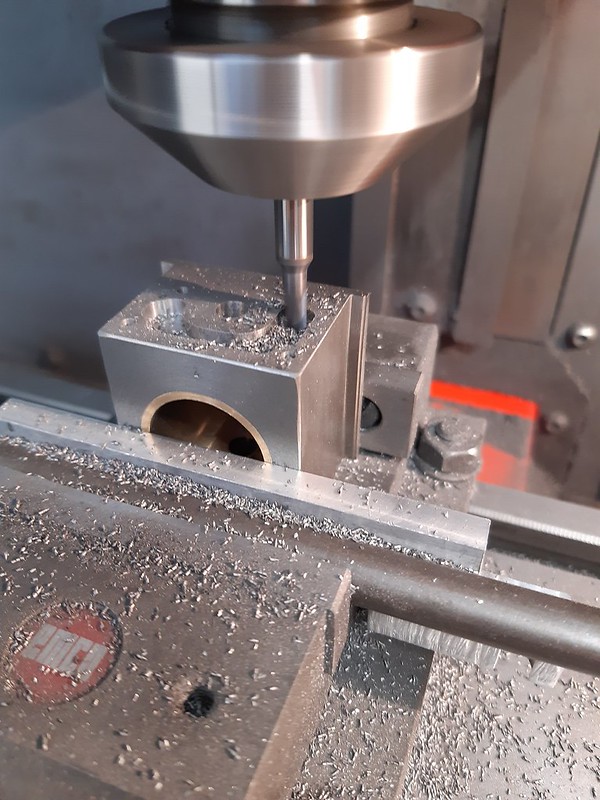 AxleboxMilling AxleboxMilling by Wilf, on Flickr And here's the computer screen, whilst milling the pocket on the bottom:  Mach3Screen Mach3Screen by Wilf, on Flickr At the top right of the screen is a representation of the toolpath - there are three helical moves, to create pockets of three diameters. The tool path is not very well thought out. Seeing it now, I should have done each depth in two passes, rather than one, and could then have use a faster helix. And here's the result:  AxleboxesWithPockets AxleboxesWithPockets by Wilf, on Flickr On the left you see the bottom. There's a central 6mm hole right through for the felt to touch the axle - this is an experiment, I may increase the size in due course. Then there's a 10 mm pocket, where the 45 degree oil holes come in. then there's the largest diameter, threaded 9/16" x 40tpi for the plug - which will have a 6mm cup to hold and centralise the other end of the felt. On the right is the top view. These are handed - I just told the CNC to "scale" the X-axis by -1 and it did everything the other way round (the lazy approach - I should have prepared a second G-code file). In the bottom of the pocket is one of the plain 1.5mm holes, for the oil to go down to the felt at the bottom. The other plain hole is for air to come back up. The central threaded hole is for the post to the spring-beam, and the three smaller threaded holes are for fixing screws of the cover. What I need to make next are the posts, covers and bottom plugs. Wilf |
|
timb
Statesman

Posts: 512 
|
Post by timb on Jun 10, 2020 15:29:25 GMT
I just gave a shudder thinking of trying to mill that with my manual!
Tim
|
|
Gary L
Elder Statesman
Posts: 1,208
|
Post by Gary L on Jun 10, 2020 19:12:15 GMT
Also worthy of note are the series of articles in the 1970 Model Engineer of which I have borrowed copies from the Club at present. WELL on Page 132 and 133 6 of FEB 1970 volume 136 number 3386 which should come up on any digital database! There are 3 lovely photos showing Kens own model complete with a Wonderful Lubrication system all fed from one box on the footplate side. A One Shot system which also covers the axle pump. Again wonderful drawings. Upon reading through the only other problem encountered with the model so be warned!!!! Is that Bridget has worn out 2 sets of Superheaters. Now judging by the the lovely YOUNG photo on page 129 he loved driving her so much so that a mileometer was fitted. OH and one more thing... November 1966 a new chimney was fitted? Possibly new draughting was tried and it worked. David and Lily. Hi David I’ve mentioned Ken’s superheater failures before. Not everyone agrees with me, but I believe the issue arises because he didn’t draw ‘spider’ supports at the throatplate end of the superheater elements. These are not often detailed on miniature loco drawings to be fair (Paddington is an honourable exception for once) which I find surprising for something so cheap and easy to make, and which is found on all full-size locos. The concentric elements drawn by Ken are quite heavy, and I don’t like the idea of the dynamic stress being entirely carried by the header as they bounce up and down with the motion of the engine. If the elements are the extra-long radiant’ type, this just makes the unfair stresses worse. No criticism of Ken’s wonderful drawings intended; we can all find small things to change and improve, and often do. HTH Gary |
|
uuu
Elder Statesman
your message here...
Posts: 2,808
|
Post by uuu on Jun 10, 2020 20:15:54 GMT
There are a few other points to be drawn from a reading of the ME articles: - Chimney was changed from a straight to a tapered one. I suspect this may have been an aesthetic change, but may have coincidentally improved the draughting.
- Bridget was a vigorous steamer - was this behind the reduction of boiler pressure between Bridget and Jessie (from 120psi to 100psi)?
- A derailing exposed the vulnerability of Bridget's draincocks. Jessie's inclined motion lifts these to a safer position.
- Ken wore out his axleboxes. Jessie's journals are larger diameter and wider than the ME Bridget drawings.
- Jessie's dragbox is better - it provides top and bottom support for the coupling hook, rather than top only.
- Interestingly, the Bridget drawing in ME shows a spear-point superheater, not the concentric type!
- Jessie's axle pump is smaller bore.
- Jessie's safety valves have a larger bore
It might be that some of these changes are incorporated in the published Bridget drawings - I'm just looking at the ones in the ME articles. Wilf Edit - I see the axles in one of the later Bridget ME instalments incorporate the larger journals. |
|
dscott
Elder Statesman
Posts: 2,438
|
Post by dscott on Jun 10, 2020 23:35:47 GMT
Lovely work Wilf, I managed a couple of hours but mainly doing a sort out. The rain did not help so we went shopping instead. ibb.co/ykf9XDyJust adding this as not everyone has access to a copy of a 1970s Model Engineer. 1970 Dad bought me a Copy and I still remember looking at the 2 cross sections of Bridget... Never dreaming of the day I would be doing her sister. David and Lily. |
|
uuu
Elder Statesman
your message here...
Posts: 2,808
|
Post by uuu on Jun 11, 2020 11:57:53 GMT
An easy job done, before I tackle the covers and plugs. These are the posts that connect with the spring beams. As the drawing directs "screw in tight", I screwcut the thread and followed with a split die, opened out to be a close fit. And for good luck I used a threadlocker.  AxleboxesWithPosts AxleboxesWithPosts by Wilf, on Flickr The springs are from Ashfield Springs. I bought these years ago, when they had a minimum order value, but that seems to have gone. I don't yet know if the rate is right, but they're to the spec on the drawing, and they look good. Wilf |
|
dscott
Elder Statesman
Posts: 2,438
|
Post by dscott on Jun 11, 2020 23:09:10 GMT
I took mine off very early on having cut myself on an end!!! Honestly I could have shaved with them.
This was a theme with every part including the frames. Yes just taken off the machine and put in place.
Mine now look like yours more like the forgings they would have been in full size.
I find filing very satisfying and have many drawers of them. They have a descending line of duty starting as new doing Brass!
The Mucky Mob relegated to wheel castings.
For my threading I have managed to gain many BA dies so am in a position to go down with a course and then a fine set to a nice fit
usually the high speed one. Many have come within the packaging of acquired part builds!
Are we allowed SPRING ENVY? They had SPRING WATCH Last time I watched TV!!
All looking wonderful Wilf.
David and Lily.
|
|
uuu
Elder Statesman
your message here...
Posts: 2,808
|
Post by uuu on Jun 18, 2020 13:38:35 GMT
Good news and bad news to report. Start with the good - behold the magnificence that is the ashpan:  JessieAshpan JessieAshpan by Wilf, on Flickr I thought I'd give this laser cutting a go. So I got in touch with Malcolm at Model Engineers Laser. He'd not got the Jessie ashpan design, so I ran up a DXF file and sent it to him. I incorporated a few features that I thought would be helpful: - It's 1/32" wider than specified, for an easy fit to the boiler - I didn't want to wedge it on. That's good, you can see it sits on the boiler sideways with only friction holding it.
- I've added rows of tiny holes in the base, where the bends go. This wasn't to weaken it at the bend point, but as a guide for where to bend. That's worked, too - it was easy to get the blade of the fly press in just the right spot.
- I've added tabs and slots, so it assembles for jointing, either by welding or brazing. I'll grind them off afterwards. This has worked also - which is a little bit of a miracle, as I had to deduct a bend allowance into the flat dimensions. A few strokes of the file on the lengths of the tabs and it's tapped together, held at the moment by friction.
So - what's the bad news I hear you ask? It's too bloody big! Brain fade on my part when I drew it out in CAD. There's a 2 3/4" dimension (the horizontal length of the sloping part), and a 2 1/4" one (the overall height). A typo on my part has both dimensions at the bigger figure, so it's too deep. It will foul on the axle when fitted. I suppose I could cut this one down, but that rather spoils the whole point of an easy-assemble laser-cut kit. So I'll re-do the DXF file and get Malcolm to cut me out another one. I may make a few tweaks: - I can trim my 1/32" extra width down just a touch.
- The rear mounting holes, positioned as the drawing, line up with the edge of the firebox flange as it bends round the side. They'd work here, but if I move them forwards 2mm, they'll just clear, making the drilling and tapping into the copper easier.
- I may add a little slot at each end of the bend. This will help the bend to be sharper at this point (the holes have helped it fold better in the middle than the very sides.
Wilf Edit: Quick check. Ken has provided 3/4" holes in the main frame so the ashpan mounting bolts are accessible. Moving them forward 2mm should not compromise this. |
|
dscott
Elder Statesman
Posts: 2,438
|
Post by dscott on Jun 18, 2020 19:31:04 GMT
Now we get ASHPAN ENVY!!!
And here is me getting the cornflake packets out and angle grinding something to suite.
Also in Stainless and an odd sheet I have hanging around.
Also many stainless bars from window openings. Lets see how easy they are to melt through.
Just doing another War and Peace for the Prospectus our Club Rag.
Going Through the Motions.
Nice Boiler Wilf Mine is a bit old but unused.
David and Lily.
|
|
uuu
Elder Statesman
your message here...
Posts: 2,808
|
Post by uuu on Jun 26, 2020 13:57:55 GMT
I'm not sure why I've been going more slowly - but things are at least moving forwards. I've done the screw-in bungs for the felt pockets under the axleboxes. And made a tool to unscrew them:  AxleboxBungs AxleboxBungs by Wilf, on Flickr I'm also feeling happy because I've measured the axle spacing, with a view to starting on the coupling rods. One side is dead on, the other is two thou over. So the wheels should go round, when I get that far. Wilf |
|
mbrown
Elder Statesman
Posts: 1,719
|
Post by mbrown on Jun 26, 2020 14:00:20 GMT
Very nifty! Rather like the secure wheel nut you get on cars (where you can never remember where you put the tool when it comes to the next service....!)
Malcolm
|
|
uuu
Elder Statesman
your message here...
Posts: 2,808
|
Post by uuu on Jun 26, 2020 14:02:59 GMT
I could have just put a straight slot in. But I thought that I'd make it obvious there was a special tool for it, to remind myself not to attack it with any old screwdriver.
Wilf
|
|
|
|
Post by ettingtonliam on Jun 26, 2020 14:06:29 GMT
I'm not sure why I've been going more slowly - but things are at least moving forwards. I've done the screw-in bungs for the felt pockets under the axleboxes. And made a tool to unscrew them: AxleboxBungs by Wilf, on Flickr I'm also feeling happy because I've measured the axle spacing, with a view to starting on the coupling rods. One side is dead on, the other is two thou over. So the wheels should go round, when I get that far. Wilf A couple of thou? no problem! I'm still pondering how to deal with the fact that, with Locomotion's axlebox carriers both bolted to the boiler, when it gets up to temperature, expansion makes the axles about 20 thou further apart than when they are at an ambient of about 20C. |
|
uuu
Elder Statesman
your message here...
Posts: 2,808
|
Post by uuu on Jun 26, 2020 14:13:34 GMT
Springs one side of the brasses in the coupling rods?
Wilf
|
|
|
|
Post by Roger on Jun 26, 2020 16:21:08 GMT
I'm not sure why I've been going more slowly - but things are at least moving forwards. I've done the screw-in bungs for the felt pockets under the axleboxes. And made a tool to unscrew them: AxleboxBungs by Wilf, on Flickr I'm also feeling happy because I've measured the axle spacing, with a view to starting on the coupling rods. One side is dead on, the other is two thou over. So the wheels should go round, when I get that far. Wilf Hi Wilf, What sort of seal are you using for those? Presumably they won't need to come out again for a very long time, so some sort of gasket sealant comes to mind? |
|
uuu
Elder Statesman
your message here...
Posts: 2,808
|
Post by uuu on Jun 26, 2020 18:22:56 GMT
I haven't tested them yet, to see how oil tight the threads are. At the top of the thread, where the tap runs out, there's a tighter fit. I've fitted each piece to suit.
But you're probably right, that they will leak unless I use some gloop. I'll start with "Heldite" and see how that performs.
Wilf
|
|


