|
|
Post by ettingtonliam on Jun 26, 2020 20:54:01 GMT
Springs one side of the brasses in the coupling rods? Wilf Possibly, but these are gib and cotter jobs, relying on the cotter being knocked up fairly tight. i'm currently favouring two flat bar ties between the two axle housings, slotting the holes in the rear housing which bolt it to the boiler, and using spring washers under the bolt heads, to allow a little 'controlled' movement. I imagine that full size they just relied on plenty of slack. Contemporary reports of the S&D do suggest that there was a fair amount of rattling and clanking when the locos moved. |
|
uuu
Elder Statesman
 your message here...
Posts: 2,807
|
Post by uuu on Jul 12, 2020 10:17:58 GMT
Slow progress on the axlebox covers (but better than nothing):  AxleboxCovers AxleboxCovers by Wilf, on Flickr These are just bits of 1/8" thick brass - with holes in the right place, and an extra bit soldered on top to take the entry point for oil on the edge. Solder used was some old cadmium stuff, because I had that in thin rods. Little pegs held the extra bits in position, although the first one floated up as the solder penetrated and needed poking down, so I tied the other three down with florists wire (there's a solder mark on one where the wire got stuck down). Next step is to machine to final size and do rounded edges. Wilf |
|
uuu
Elder Statesman
your message here...
Posts: 2,807
|
Post by uuu on Jul 15, 2020 8:54:01 GMT
More slow progress:  AxleboxCovers2 AxleboxCovers2 by Wilf, on Flickr I've done the profiling - It was a bit fiddly to get all the toolpaths right, to miss the hold-down screws. My apologies for the poor photo - the reflections are a bit disruptive. Wilf PS - yet to add the hole for the oil gun to go in. |
|
|
|
Post by Roger on Jul 15, 2020 19:53:13 GMT
Hi Wilf,
Great results, very neat. I'm curious to know why you didn't machine these out of round bar as a 'part on a stick', including the lump on the top?
|
|
uuu
Elder Statesman
your message here...
Posts: 2,807
|
Post by uuu on Jul 15, 2020 20:06:30 GMT
I just used some stuff I had. Perhaps I've picked this habit up from John and others, where every effort is used to find something, anything, in the odds and ends bin that can be put to use. Even if it is ten times the effort!
Wilf
|
|
|
|
Post by David on Jul 16, 2020 23:03:56 GMT
It would be an expensive bar, have to be a pretty big diameter.
|
|
uuu
Elder Statesman
your message here...
Posts: 2,807
|
Post by uuu on Jul 31, 2020 17:03:57 GMT
Having received the right-size ashpan parts from MEL a little while ago (see previous post about my cock-up), I thought I'd have a go at assembling them. But should I weld or solder? I had first thought I'd get John the Pump to tack-weld the tab-and-slots with his TIG kit and then solder together without fear of it falling apart half way. Then John had practised TIG seaming with some spare bits of stainless, using a pulsing method. The results were very good. But I thought I'd have a go at just soldering the wrong-size kit as an experiment, then make my mind up. The tab and slots held together quite well with just friction, but a few taps with a centre-punch to swell the tabs made the whole thing very rigid, so no need for tack welding after all. I laid a line of Silver-flo 40 along the inside, fluxed up with Tenacity 5 then heated from the outside to draw the solder through the joint. It went really well, leaving a nice fillet of solder on the inside, and showing a thin gold line all along the outside of the joint, and fillets round each tab. So I carried on with the right-size kit. First photo is of the set-up. The lower side was soldered, then the whole thing flipped to do the other one. The spacer rod is a piece of old stair rod.  Ashpan1 Ashpan1 by Wilf, on Flickr Second photo is the result after a hot caustic wash to remove the flux residue. 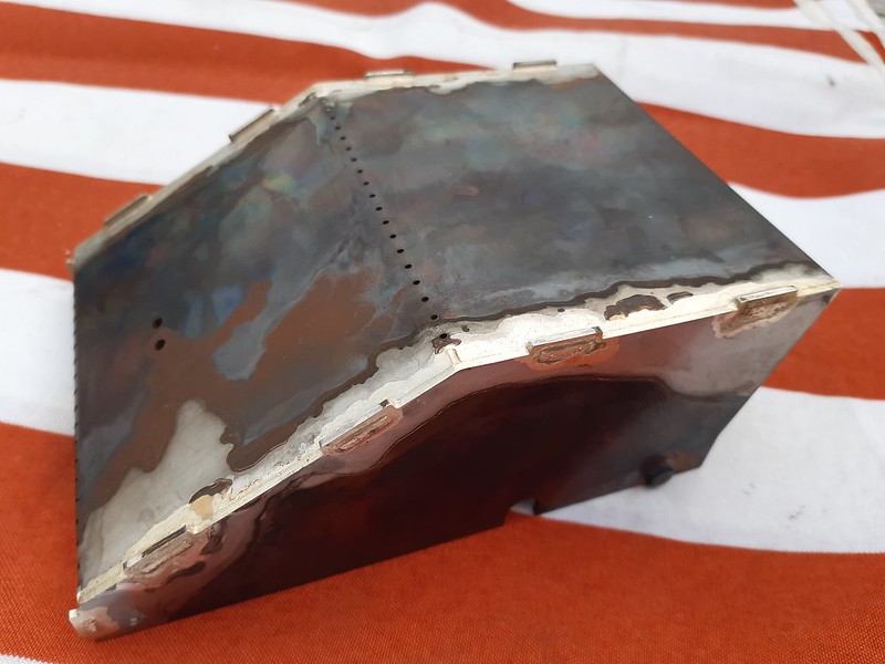 Ashpan2 Ashpan2 by Wilf, on Flickr I've now got to file/grind off the tabs and clean up. Wilf |
|
uuu
Elder Statesman
your message here...
Posts: 2,807
|
Post by uuu on Aug 6, 2020 13:38:50 GMT
I've not had much experience with an angle grinder - but it seemed the ideal tool to attack the tabs/slots on the ashpan. And so it proved - it was more controllable than I had imagined, and I managed the job without gouging it. I needed to see that it fitted the boiler OK: I was pleased I had allowed an extra 1/32" on the width - it slipped on just right. While it was resting there I thought I might as well drill and tap the fixing holes (the boiler lives in a fitted box under the mill and is a bit of pain to get out). Drilling into the boiler makes me nervous, even if it's only into the firebox skirt. Here's the set-up for the first hole:  Boiler1 Boiler1 by Wilf, on Flickr And here's tapping the second hole:  Boiler2 Boiler2 by Wilf, on Flickr In for a penny... Here's the ashpan in place, and I've just drilled the hole for the grate pivot (this lines up with an opening in the frame, so a key can be used to dump the fire):  Boiler3 Boiler3 by Wilf, on Flickr Meanwhile, I've also make the tail rods that brace the open ends of the horns and limit the downward motion of the axleboxes. Wilf |
|
smallbrother
Elder Statesman
Errors aplenty, progress slow, but progress nonetheless!
Posts: 2,269
|
Post by smallbrother on Aug 6, 2020 18:23:14 GMT
Looking very nice indeed Wilf.
I am itching to do some soldering of the platework for Juliet. All from MEL.
As our club is re-opening on Saturday I may take some parts along and get a few tips.
Pete.
|
|
uuu
Elder Statesman
your message here...
Posts: 2,807
|
Post by uuu on Aug 7, 2020 13:09:33 GMT
Pressing the crankpins into the wheels: Crankpins were made some time ago. These would have been turned, and the wheels bored, on my knackered old Myford when it, together with my own lack of competence, mitigated against repeat turning to tenths of a thou. I've selected the wheel and pin pairs so that the fronts have the least interference and the rears the most, thinking that the rears have to drive the eccentric cranks. Here's the first one going in:  Crankpin Crankpin by Wilf, on Flickr The rear of the wheel is supported by a hexagon socket, and the pin has a fitting that applies the pressure inside, rather than on the rim. The fronts went in easily enough - I've added Loctite as a belt-and-braces measure. I've decided to defer doing the rears until I can get to the Pump House, where I can use the arbour press - they'll need a stronger push. Wilf |
|
dscott
Elder Statesman
Posts: 2,437
|
Post by dscott on Aug 8, 2020 1:19:47 GMT
So lovely to see progress after our Month down in Plymouth away from computers and metal working.
Then I get back and its rescue Lathes from the Scrapman if anyone didn't collect.
My wheels are done but in future I will have a Denby Flypress to do them in.
This will be collected on Monday from the workshop in the woods.
The Brothers collected all sorts of stuff over the years and it's just try and get rid of before the 6 acres is sold.
Their Father built the bungalow in the late 1940s and it is showing its age. Also the workshop which
had a leaking roof for many years. Machines not touched for 30 years at least.
Then people ask "Why models take so long to complete!!"
Best Regards
David and Lily.
Plymouth was a working holiday with the electrics getting a pass certificate first time.
And mostly redecorated.
|
|
uuu
Elder Statesman
your message here...
Posts: 2,807
|
Post by uuu on Aug 19, 2020 17:36:30 GMT
I thought I'd have a go at the motion brackets. I bought castings for these at the start, so a different route from Ken Swan's original and David and Lily, where built-up brackets were used. Quite a while ago, I'd put these in the four-jaw and flatted the mounting face and the one opposite, and brought to size. Last weekend, I put them on the mill table, against an angle plate, to mill the top and bottom faces square with the first two, and again brought to size. Today I thought I would finish the mounting face - adding the fixing holes and profiling the shape. As the motion is at an angle, the corners aren't square, and the fixing holes are also on the slant. Setting the casting in the vice - with a clamp-down for additional security, I established the Y-axis position with a wobbler on the top face. The X-axis was a little more difficult. I scribed a line in the middle of the central web and found this with a pin:  MotionBracket1 MotionBracket1 by Wilf, on Flickr The Z axis was initialised in my usual way - gently holding a 6mm roller against the side of the tool, and slowly raising the spindle until the roller passed underneath: 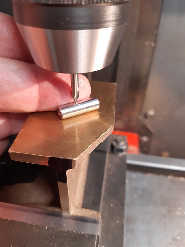 MotionBracket2 MotionBracket2 by Wilf, on Flickr Holes were drilled. There are two for locating dowels and seven 4BA clearance for bolting:  MotionBracket3 MotionBracket3 by Wilf, on Flickr Then the outside profile was cut (this is the other handed one from the previous photos). I've modified the shape of the cutout giving clearance for the wheel. The drawing has this as a straight diagonal, but I've added a curve to give more room. As drawn I think there may be a conflict with the wheel flange when the wheel is at full bump. Certainly it's very close on my frames which are upside-down so, without springs, the wheels are right at the top of their range.  MotionBeacket4 MotionBeacket4 by Wilf, on Flickr The castings are barely big enough. They're fine really - there was plenty of meat on the main flat faces - but profiling around the mounting face exposed a slight undersize on the front of one and both front and back of the other. As I'm using the rear face of this as a datum for the X-axis for subsequent machining, I've milled a short flat 0.5mm in from the as-drawn top edge. The loco was designed to be makeable on a Myford 7 with milling on the vertical slide, so I suppose it was expected to just clean up the outer shape with a file. No-one will notice unless they have a torch and magnifying glass on hand. Wilf |
|
uuu
Elder Statesman
your message here...
Posts: 2,807
|
Post by uuu on Aug 25, 2020 10:46:27 GMT
Bum! OK - this picture is a lot like the previous ones:  MotionBracket5 MotionBracket5 by Wilf, on Flickr But here I'm planning to machine the outer side of the motion bracket - and I'd like the outside and inside to line up. So... not being able to reach under the overhang to get the wobbler to the datum point on the frame mounting flange, I thought I'd make a jig. Using the same program that drilled the mounting flange holes to drill those in the jig, anything I then machined on the outer face would exactly line up. And so it is - in the picture I've just spotted three hole positions. The one on the right is the critical one, that's where the expansion link pivots, so it needs to be correct. The two on the left are not so important - just for dowels to locate an upstand that will be soldered on - to hold the outer expansion link bracket. So far, so good. But things go wrong when I go to machine the outside profile. I haven't got enough movement in Y to get round the bottom. I've set up the jig too far south. It's not too much of a big deal. The outer profile is not so critical - there's only the mounting on the toe of the casting for the slide bar - but it has shims, so a thou or two will not matter. Two choices - and I'm not sure which to take at the moment. I can put the casting in the vice to do the next bit. Or I can modify the mounting of the jig to move it up a bit, into range. One of the hazards of having a tiny mill - I've only got about 75mm of Y travel. At least it's a beefy tiny mill Wilf |
|
uuu
Elder Statesman
your message here...
Posts: 2,807
|
Post by uuu on Aug 25, 2020 15:32:03 GMT
I decided to shift the jig up, as the easiest option - just drill two new mounting holes and re-tram it square. So here's the first profile being cut:  MotionBracket6 MotionBracket6 by Wilf, on Flickr You can now see the 3/8" hole for the expansion link, and the angled bottom surface on the toe for the slide bar. What you can't see it it cutting fresh air on the right hand side, where the casting is a mm or so under. I'll have to see how that looks when I've soldered on the extra bit for the outer expansion link bracket. I suspect that will stand proud, so I may have to either solder on a repair, or use some plastic padding to make this up to size. Wilf |
|
dscott
Elder Statesman
Posts: 2,437
|
Post by dscott on Aug 27, 2020 3:30:12 GMT
Super Steel Users Anonimouse for me!
Trouble is I keep reaching out for it but helps get out of trouble and is all over in 5 minutes.
I have also experimented with adding more filings which still works well.
I was working on the last items that need holes via the frames.
The guard irons (For display) And a set of Angles for track running in case she jumps the track.
All secured through the same holes. Almost there. Doing little bits in between major jobs.
David and Lily.
|
|
|
|
Post by Roger on Aug 27, 2020 7:57:42 GMT
Nice work Wilf. This business of not being able to reach round a job still happens whatever size mill you have. The Y-axis is always going to be the limiting one. Fortunately Mach4 shows me the tool path limits, so I usually load the profile path and jog to the limits of those to make sure I can reach. It's often touch and go. Sometimes I have to use a much smaller cutter than I would like to, just so I can reach around a profile. Such is life.
|
|
|
|
Post by steamer5 on Aug 28, 2020 3:59:00 GMT
Hi Wilf,
Nice work. Just as a thought if you had turned the part 90 degrees with what is now the y axis running in the x axis direction would that allowed you the extra room? I guess the next issue would be holding it!
Cheers Kerrin
|
|
uuu
Elder Statesman
your message here...
Posts: 2,807
|
Post by uuu on Aug 28, 2020 6:14:22 GMT
It wasn't so much that the part was too big - it was that my jig had been made wrong. So I was kicking myself, knowing that I could have got it right first time.
It's a shame the mill does not have a tee-slot nearer the middle. The ones down the edge make clamping harder - there's nowhere to put the tail support for the clamp if its head is pointing inwards
John at the Pump House has an aluminium plate on his mill, peppered with a grid of threaded holes, making clamping easy anywhere you like. I might try and arrange something similar.
Next challenge is the coupling rods. These will be too long to do in one go, so I'll need to organise a turn-around fixture.
Wilf
|
|


