|
|
Post by John Baguley on Dec 13, 2020 13:29:43 GMT
Hello Michael,
Your method of determining the lap and lead of the valve seems logical although see notes elsewhere about whether you need lead or not (your choice). Your 0.2mm is reasonable though and not excessive. You are stuck with the valve travel in mid gear anyway unless you alter the dimensions of the combination lever which would mean making a new one.
You can work out the maximum cut off in full gear once you know the lap of the valve by measuring the total travel of the valve from the loco itself. There is a formula in Martin Evans' book 'Locomotive Valve gears' that I adapted and made a spreadsheet to work it out.
The formula is:
Cut off = Port opening² + 2(Port Opening x Lap) ------------------------------------------- x 100%
(Port Opening + Lap)²
From my spreadsheet I have calculated that to get 75% cut off in full gear with a lap of 3.8mm you will need a total valve travel of 15.2mm when the reverser is in full gear. That will mean that the ports open by 3.8mm.
If the valve travel is sufficient to fully open the ports then the cut off will be 81.35%
The only way to determine if the cut offs will be equal for each end of the cylinder is to measure all the components of the valve gear as you suggest.
Hope that helps,
John
|
|
|
|
Post by mikessme on Dec 13, 2020 18:35:19 GMT
Hi Michael, I did some measurement on my B5 as requested. Dimensions are very similar to what you have, although as John mentions I have taken the dimensions over the rings as the end caps and bobbins are slightly undersize. Full forward gear valve travel is 14.4mm, Mid gear 8.2mm and full reverse gear 14.56mm. This gives a Lap of 2.72 and a lead of 1.38, figures very similar to those you mention if measured from the bobbin edge. 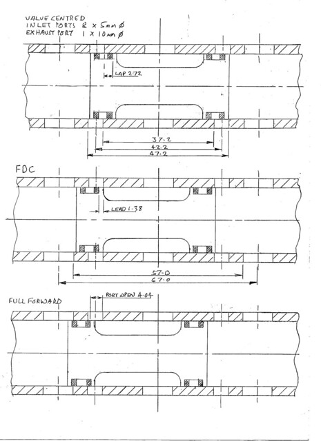 Black 5 valve timing Black 5 valve timing by Mike Sanderman, on Flickr Mike |
|
|
|
Post by michaelfive on Dec 14, 2020 19:58:49 GMT
Dear John, thanks for providing the formula and for your explanations.
Dear Mike, thanks for measuring and for providing the sketches.
It doesn’t look like the dimensions of the valve gear were altered a lot by MW. The fact that Mike has well running engine with the same valve travel than mine, makes me confident again, that I can make my engine run without changing the gear. I could basically just make the size of the heads to match the specifications of Mikes sketches.
When I apply the Martin Evens formula provided by John on the values measured by Mike (port open 4.04, Lap 2.72) I get an admission of 84%.
But whats surprising me, is the amount of lead on Mikes setup. And what I don’t understand, is why lead must not be considered for calculating admission?
Doesen’t it matter when admission begins?! With a lot of lead admission starts already before death center, without lead just after death center. That must make a difference, mustn't it?
You see i’m an absolute beginner in these questions, but would really like to understand the mechanism behind.
|
|
|
|
Post by mikessme on Dec 14, 2020 21:57:30 GMT
Dear Michael, if you haven't already been there it's worth a look at John's website where you will find some very clear descriptions of valve events.
I gave the piston dimensions from the rings as the end caps and the bobbin body are slightly undersize and you will get some steam passing these areas after the ring passes the port edge. When I set my valves up I pressurised the boiler slightly with air and removed the balls from the cylinder drain cocks, then with a flexible tube into a jar of water it was easy to see when the valves opened and to equalise them at each dead centre, but this may be more difficult to do with PTFE rings as these will be undersize when cold.
I would also be interested in Johns comments on port shape, with the circular ports on these valves opening will be slow in comparison to a square edge, although as the open port area does not cause a restriction I don't know if this would make any difference in practice.
Mike
|
|
|
|
Post by steamer5 on Dec 15, 2020 1:04:57 GMT
Hi Guys,
This is a very interesting discussion to be following!
Just to put 2 cents worth in about the PTFE rings for piston valves....I was given an article some years ago on making these, the article comes from South Australia via a guy in Queensland. The recommendation there is the ring should be a push fit into the bore of the linear, the wall thickness no more than 3/32” or 2.4 mm & the bore to be the diameter of the land on the valve body PLUS 0.003” to allow for inward expansion, the width to be the width of the land on the valve body PLUS 0.001”. The article says they are have great success with these.
Maybe somebody in Australia has done this or is knows of a locomotive or 3 that’s running this & can give us an update.....
Cheers Kerrin
|
|
|
|
Post by michaelfive on Dec 15, 2020 5:15:11 GMT
Dear Michael, if you haven't already been there it's worth a look at John's website where you will find some very clear descriptions of valve events. I gave the piston dimensions from the rings as the end caps and the bobbin body are slightly undersize and you will get some steam passing these areas after the ring passes the port edge. When I set my valves up I pressurised the boiler slightly with air and removed the balls from the cylinder drain cocks, then with a flexible tube into a jar of water it was easy to see when the valves opened and to equalise them at each dead centre, but this may be more difficult to do with PTFE rings as these will be undersize when cold. I would also be interested in Johns comments on port shape, with the circular ports on these valves opening will be slow in comparison to a square edge, although as the open port area does not cause a restriction I don't know if this would make any difference in practice. Mike Thanks, Mike! I found some more or less usefull information about valve events on the web. But i'dont think that i found John's website yet. Would you mind to post a link? |
|
|
|
Post by John Baguley on Dec 15, 2020 13:13:43 GMT
Hello Michael,
Please note that the website is not a 'How things should be done' type of website. It's just a diary of things I have done over the years, how I have done them and some thoughts on various aspects of model locomotive design. There are many people out there far more knowledgeable than me 
Re lead - yes it does affect when the admission of steam begins into the cylinder but was necessary with full sized locos as has been mentioned. It was used to allow the steam to enter the cylinder early to help cushion the piston at the end of it's stroke when it has to slow down rapidly and change direction. In a model the weight of the piston is negligible and the piston speeds are much lower than in full size. In a full size loco the steam passages have significant length and there is a delay between the valve opening and the steam filling the cylinder. In a model the passages are very short and the steam admission is virtually instantaneous.
One big disadvantage with having too much lead is the steam can enter the cylinder too early and actually opposes the movement of the piston. Walschaerts' valve gear is known as a 'constant lead' valve gear. The amount of lead (how much the port is open at top and bottom dead centres) remains the same no matter what the cut off is but the point at which the valve opens changes as the cut off is altered. The valve opens the port earlier and earlier as the cut off is decreased. This is known as pre-admission.
I notice this on my Helen Long where I gave the valve gear a 'normal' amount of lead (I didn't know better at the time!). The valve gear is very good and notches up well. However, If I reduce the cut off too far the loco becomes very jerky in it's running because the pre-admission has increased so much that the steam is actually trying to push the piston back the other way and opposes the motion.
Lead is not used in the cut off calculations because the cut off point is controlled by the valve closing the steam port. The lead affects the port when it opens, not when it closes as it is a feature of the valve gear, not the valve itself. That makes me think whether Martin Evans is correct in what he says in his valve gear book? He says that the lead affects the cut off figure but does it? I'm not sure that it does.
Mike - leaving the ports round will have some effect on the performance but whether you would notice it dring normal club running is open to debate. Squaring the ports off will increase the area of the port when it opens and allows the steam to enter the cylinder so the cylinder will fill quicker. Similarly, it wil also allow the exhaust steam to exit quicker and you will get a sharper exhaust. If you are chasing maximim efficiency or prizes at IMLEC then I would say yes, square the ports off. If you just want a loco that runs and you are not too fussed about the performance then the round ports will probably be fine. As mentioned above, the steam passages are so short in a model that steam admission and exit is pretty much instant. I would suggest that getting the valve events right will have far more effect than the shape of the ports.
Kerrin - yes, that's pretty much how I made the valve heads for my Helen Long. The PTFE sleeves are 1/16" thick and were made a push fit into the valve liners. The loco is now 12 years old and the valves still seal perfectly with no blow whatsoever. I also fitted PTFE piston rings and they are still fine as well.
John
|
|
|
|
Post by ettingtonliam on Dec 15, 2020 13:32:39 GMT
If timing is done using the edge of the rings, it might be an advantage to chamfer the ends of the bobbins, so steam gets out of the ports easily when the rings pass them, rather than initially having to squeeze past the end of the bobbin. Done in full size practice I believe.
|
|
|
|
Post by michaelfive on Dec 16, 2020 18:04:51 GMT
Dear John
Thanks for the link. Your website is indeed an interesting read! I am glad that mike pointed it out. I read the introduction to valve gear and found it written in clear and comprehensible language! Even understandable for a nonnative English speaker like me 😊 I will definitively spend so more time reading on your projects.
Below is what I learned for my valve project:
- Cut off (And therefor admission) is defined by the time the port closes and not the time it opens. - If I don’t want to alter the gear, the only way to increase admission is to reduce lap and increase valve opening. - To reduce lap I will need to shorten the valve heads on the side of the live steam port which will increase the port opening in full gear. - If I reduce lap I will increase lead. (Since I do not alter valve travel in mid gear) - If the above is correct I will need to find a good compromise between to much lead and insufficient admission.
I used the formula provided by John to find that optimum: If I go for 3.6mm lap (bobbin heads width 8.6mm) I have a port opening in full gear of also 3.6mm which leads to an admission of 75%. In that case the Lead of the valve would be 0.4mm Does this sound reasonable? |
|
|
|
Post by michaelfive on Dec 25, 2020 16:02:17 GMT
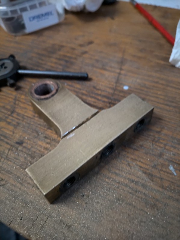
I finally made the valve bobbins according to the dimensions above. I made the valves adjustable from the front, by removing the valve cover, as others explained in that forum. The valves brass bobbins "float" on a threaded aluminum rod. The rod can be fixed on the SST valve piston rod by a lock nut. The tyres ar made of virgin PTFE that i will exchange to graphite loaded PTFE once I’m sure that they have the correct length. I made the outer dimension to a push fit to the valve liner and allowed clearance for expansion on the inner diameter, that sits on the brass bobbins.
But when i begun to mount and adjust the valves I found another surprise: The valve travel is not identical on both cylinders. Naively as I am, I only measured one valve to get the dimensions and the travel from. Unfortunately there is a big difference between the two valves. That’s maybe the reasen why the old bobbins were not made to the same dimension. Mayby someone tried to correct an error that was introduced on another location.
Where in mid gear the difference in travel is only 0.2mm, the difference in full forward is 2.55mm!
I did not yet find the divergency between the two sides. I already compared the lenght of all the rods of the valve gear, and measured the location of the pivoting point of the links.
I’m a bit confused, since I’m definitely missing something but cannot find it.
In those situations, I learned that it’s better to stop the “debugging” actions and do something else for a while. I will reevaluate the problem later with a free up mind.
So I attacked something less complicated, that already bothered me for a while: The threaded bushes on the top of the boiler are welded inclined. Thus, the steam turret is not horizontal.
Even that it can bee seen in the picture below I in reality it's even worse.
I made a quick fix, by parting the turret in two halves and by machining a brass tube that can be threaded between the two parts.
This allows me to set the front part of the turret parallel to the cab floor.
The part that connects to the steam outlet is obviously still inclined but with the cab re mounted it will not be visible.
I will have to find a solution for the safety valves as well, since those bushes are neither solded vertically.
I wish you all a merry Xmas!!
|
|
|
|
Post by michaelfive on Jan 9, 2021 10:45:11 GMT
There was not much going on in my workshop the last weeks since we spent the christmas hollydays in the mountains with the family.
I still don't really found the cause for the different valve travel of the two valves.
So I started to again disassamble the valve gear, motion and the cylinders.
What I found out so far, is that the rotation point of the expansion links is about 1mm offset form one side to the other. Most of the individual componets i measured seam of identical size (within a reasonable tolerance) but the addition of the tolerances (mounting and machining) apparently lead to that offset.
I don't think that this is the main source of the difference in valve travel, but i for sure has an influence and i want to sort it out anyway!
The first components that i needed to remachine were the front pistom covers that have a difference in thickness of 0.5mm.
The covers hold the slide bars for the crosshead and those are connected to the motion brackets that holds expansion link supports.
The initial plan was to keep the CI main pistons with the Silicone O-Rings for the momment and run the engine on aire with the new valve bobbins. But since i needed to disassamble everything again, i will machine the new pistons now.
I plan then to reassemble both sides of the engine part by part in parallel and measure out every step to make sure everything is identical.
|
|
|
|
Post by michaelfive on Jan 9, 2021 10:55:34 GMT
The CI pistons in CI cylinders were a nightmare as they seized every winter despite care in condensate removal and lubrication, so these have been replaced with dural pistons with 2 CI rings each, I am very pleased with these. Mike With "dural" you refer to dural aluminium right?! Is the different thermal expansion coefficent of the aluminium alloy and CI not a problem? What clearance in diameter did you allow? Thanks again for your help! |
|
|
|
Post by Jim on Jan 9, 2021 12:33:26 GMT
Hi Guys, This is a very interesting discussion to be following! Just to put 2 cents worth in about the PTFE rings for piston valves....I was given an article some years ago on making these, the article comes from South Australia via a guy in Queensland. The recommendation there is the ring should be a push fit into the bore of the linear, the wall thickness no more than 3/32” or 2.4 mm & the bore to be the diameter of the land on the valve body PLUS 0.003” to allow for inward expansion, the width to be the width of the land on the valve body PLUS 0.001”. The article says they are have great success with these. Maybe somebody in Australia has done this or is knows of a locomotive or 3 that’s running this & can give us an update..... Cheers Kerrin The article in AME by John Wakefield of SA and Shawki Shlemon were the source of ideas for the PTFE valve rings on Boadicea's piston valves.
Hope this is of help.
Jim
|
|
oldnorton
Statesman
 5" gauge LMS enthusiast
Posts: 696
|
Post by oldnorton on Jan 9, 2021 12:58:00 GMT
I did not yet find the divergency between the two sides. I already compared the lenght of all the rods of the valve gear, and measured the location of the pivoting point of the links.
I’m a bit confused, since I’m definitely missing something but cannot find it.
Hi Michael Good to see your progress. Have you checked to see if the return cranks are set at the same and correct angle? Regarding Mike's suggestion of aluminium pistons, it is great that he has got them to work, but theory says that aluminium and cast iron might suffer similar corrosion issues - I remember hammering pistons out of a car engine that had stood for a year. One tip is allowing a sufficient gap for an oil film to remain between the piston and bore. Norm |
|
|
|
Post by michaelfive on Jan 9, 2021 16:33:44 GMT
I did not yet find the divergency between the two sides. I already compared the lenght of all the rods of the valve gear, and measured the location of the pivoting point of the links.
I’m a bit confused, since I’m definitely missing something but cannot find it.
Hi Michael Good to see your progress. Have you checked to see if the return cranks are set at the same and correct angle? Regarding Mike's suggestion of aluminium pistons, it is great that he has got them to work, but theory says that aluminium and cast iron might suffer similar corrosion issues - I remember hammering pistons out of a car engine that had stood for a year. One tip is allowing a sufficient gap for an oil film to remain between the piston and bore. Norm Thanks Norm! Well i'm must admit, that i'm not sure anymore that the cranks were at the same angle. I set them by adjusting the angle until there was no valve movement induced by the radius rod when changing the reverser in both death centers. I did this for both sides of the engine, but did not measure the obtained angles and did not compare if they were really the same. I learned that this is not the correct way to set the angle. But, now it's to late to check since i already disassembled everything. Once i have reassembled the pistons and the valve gear i will proceed as described here and see what i will get: www.jghtech.com/assets/applets/LFLSRM-Setting-Eccentric-Crank-current.pdfRegarding the pistons, what would you consider a sufficient gap for an oil film? Best, Michael |
|
oldnorton
Statesman
5" gauge LMS enthusiast
Posts: 696
|
Post by oldnorton on Jan 10, 2021 12:00:19 GMT
Regarding the pistons, what would you consider a sufficient gap for an oil film? Interesting and sensible direct question, but I am not able to give you a firm number nor calculation method for cast iron pistons in cast iron bores. Even if I might guess at a number I am not inclined to say so  as it is a more complicated problem . I did not mean to suggest previously that Mike's aluminium pistons are not a good idea, they will work fine. But in that instance one will have to make an allowance for differential thermal expansion. On motorcycles, for aluminium pistons in cast iron bores, it is generally a minimum of one thou reduction in piston diameter for each inch of bore diameter, and perhaps one and a half thou if you are going racing (figures from memory - our sprint bike forum friend might want to comment). Broadly speaking, aluminium and bronze have a difference in thermal expansion compared with steel, cast iron and stainless steel, of around one thou per inch of diameter per 100 degC. (BROADLY speaking - look up the exact numbers for small material differences) Our model engineering of piston fits in bores is generally done by feel; a nice free sliding fit with no rings fitted and no perceptible slop is what is wanted. Oil will do its job of lubricating with a very thin film present (no idea what a lubrication expert will say, but I would guess it depends on surface finish and is down to microns). The problem comes when oil is scraped away from the bearing surfaces. On a steam engine it is best if any cast iron rings do not have sharp scraper edges so that they float on an oil film, whereas an internal combustion engine is struggling to keep the oil off the bores and in the crankcase. Also, when engines stand the oil thins from a surface and on restarting there is often minimal lubrication until oil pumps or splash come into effect. This problem can show as camshaft wear on internal combustion engines. If we have a steam cylinder bore with plenty of oil in it from last year then the restarting is not a problem. But if the piston was slightly misaligned in that bore because the piston rod was not EXACTLY concentric, or the cylinder cover bore and gland are not EXACTLY concentric, then the piston might wipe the oil away from the bore in one or more spots, and leave insufficient oil to protect the metal for the next few months of damp storage (until the piston wears itself into its misaligned position after many hours of running). This is where an aluminium piston, now cool and smaller, might have an advantage? This means checking the piston and piston rod (bonded and machined as an assembly and never separated), smoothly sliding in the bore with the cover(s) fitted. If it all slides with a finger and thumb pull and push then there will be an adequate oil film remaining in the bore. Even with a good oil film there is still likely to be some fine surface corrosion of the cast iron on storage because of all the water present, but if there is a reasonable gap (half a thou?) that corrosion will not stop the piston moving and will quickly polish off when restarted. Norm |
|
|
|
Post by mikessme on Jan 13, 2021 12:45:44 GMT
Hi Michael, some interesting comments, I agree with Norm's thoughts about the piston clearance, from memory I made my aluminium ally pistons about 0.002" to 0.003" undersize to give an nice slide fit, these were fitted to the original piston rods and finish machined after assembly. I didn't take the edge off the commercial piston rings but at the time there appeared to be a nice oil film on the cylinders when hand turning, I will however following the mods with the oil pump detailed below, keep a check on this.
Not wishing to add further work for you but worth a check, when I looked at my cylinders last year following an issue with over oiling when running with excess oil from the chimney, I found on inspection one cylinder was over oiled and the other light. When I first ran the loco the spragg clutch drive to the oil pump tended to slip occasionally as the pump cams reached maximum lift and after a couple of spragg bearing replacements and a new shaft, I eventually fitted some lighter return springs for the oil pump rams to reduce the load. This seemed at first to be successful but it became apparent that one of the rams was tending to stick down occasionally resulting in the uneven delivery between the cylinders. I am addressing this problem by fitting a different design of pump which will require less load to drive and should be more reliable, but I suggest when you get running you keep an eye on the lubricator handwheel to ensure it keeps rotating.
Regards Mike
|
|
|
|
Post by michaelfive on Jan 22, 2021 15:47:26 GMT
Regarding the pistons, what would you consider a sufficient gap for an oil film? Interesting and sensible direct question, but I am not able to give you a firm number nor calculation method for cast iron pistons in cast iron bores. Even if I might guess at a number I am not inclined to say so as it is a more complicated problem . I hope that the direct question was not impolite! I just try to benefit as much as possible from knowlege of the experienced model engineers in this forum. So far this forum was a great help and all of my novice questions were answered very quickly and entirely Thank you so much!
I will give it a try with aluminum pistons and graphite loaded ptfe piston rings. As suggested I will allow additional clearance for an oil film to the clearance needed to compensate for the difference in thermal expansion. I was quite busy with other things the last weeks and just found the time to machine the new SST piston rods and blanks for the pistons. The piston blanks are machined to the final length but oversize in diameter and have an internal M8 thread to be screwed to the rods. I hope that I will be able to finish the pistons mounted on the rods this weekend. I will keep you updated with some photos.
|
|
|
|
Post by michaelfive on Jan 22, 2021 16:05:28 GMT
Hi Michael, some interesting comments, I agree with Norm's thoughts about the piston clearance, from memory I made my aluminium ally pistons about 0.002" to 0.003" undersize to give an nice slide fit, these were fitted to the original piston rods and finish machined after assembly. I didn't take the edge off the commercial piston rings but at the time there appeared to be a nice oil film on the cylinders when hand turning, I will however following the mods with the oil pump detailed below, keep a check on this. Not wishing to add further work for you but worth a check, when I looked at my cylinders last year following an issue with over oiling when running with excess oil from the chimney, I found on inspection one cylinder was over oiled and the other light. When I first ran the loco the spragg clutch drive to the oil pump tended to slip occasionally as the pump cams reached maximum lift and after a couple of spragg bearing replacements and a new shaft, I eventually fitted some lighter return springs for the oil pump rams to reduce the load. This seemed at first to be successful but it became apparent that one of the rams was tending to stick down occasionally resulting in the uneven delivery between the cylinders. I am addressing this problem by fitting a different design of pump which will require less load to drive and should be more reliable, but I suggest when you get running you keep an eye on the lubricator handwheel to ensure it keeps rotating. Thanks Mike, I will have a look at the lubricator once i sorted out the other problems. If I progress in this pace that will be only in a couple of months 😉 Anyway, the lubricator looks a bit to bulky in my opinion. Since the full size Black 5 has to individual lubricators on the running board I was thinking of maybe exchanging the big one for two smaller once with more realistic size. I don’t know yet if such are available from the model engineering suppliers and what the costs will be. Its only another thing on my wish list… |
|
|
|
Post by mikessme on Jan 23, 2021 16:06:23 GMT
Hi Michael, I don't know if you are planning to loctite the piston threads when you assemble them, this was the original spec and will prevent them coming loose in the future. I agree with your comment re the lubricator appearance, the replacement I have made is a fair bit smaller and has enabled me to make a lid which looks a bit more like the original. I believe there have been successful working versions of Wakefield lubricators in this scale although I haven't seen one, but perhaps if anyone has details or a picture of these, they would be kind enough to share them. Regards Mike  Lubricator Jan 21 Lubricator Jan 21 by Mike Sanderman, on Flickr |
|


 as it is a more complicated problem