kipford
Statesman
 Building a Don Young 5" Gauge Aspinall Class 27
Posts: 566 
|
Post by kipford on Oct 7, 2020 22:13:53 GMT
Gary
I used to use laser cutting professionally so it was a no brainer on my Aspinal to laser cut anything I could. The majority was done at work before retirement, but MEL have done quite a lot for me since. I redesigned a lot of parts to allow slot and tab construction so they effectively self jig. Once you get your mind around it all sorts of things become possible. The build looks awesome by the way.
Dave
|
|
Gary L
Elder Statesman

Posts: 1,208
|
Post by Gary L on Oct 8, 2020 0:49:04 GMT
Yes I did a set of drawings for the frames and Roger has many Photos he took of them. There are so many holes to drill not on Speedy. Also 5/16" which is quite a big measurement. This is how much wider the frames are compared with scale ones. Another reason for Speedy not looking quite right! I am doing 2 of them when I have a purge. Frames of Great Western Locomotives are a certain width? And all the same? Yes they were limited by the size of the equipment they were cut out on!!!! Makes sense. Yes I had a misspent Youth in Keith Wilson's Workshop. 1975 onwards. Was at School with his son Alan. Felow Librarians. I built a lathe for A Level as you do. Myford size. David and Lily. Keith Wilson- Respect! (as they say). What incredible productivity! -Gary |
|
dscott
Elder Statesman
Posts: 2,437
|
Post by dscott on Oct 8, 2020 0:55:21 GMT
Yes the Ken Swan drawings put lots of others in the shade.
I just go down to the workshop and make parts for Jessie and then make more and they work out.
Found 2 errors so far with the help of UUU with the motion bracket.
The other helped me to get the part built model cheaper as she was ceased as the drawing shows the leading crankpin bolt too long.
These were sticking out into the horns and preventing movement. No interest from others poor thing.
Type in 8792 in Station Road Steams box to see what I started with.
The Boiler passed first time so I was extra pleased.
Just spent 2 hours smoothing out more Dock Tank drawings. Simple things like numbering all the stays for quicker reference. Plus being good at adding Dimensions and drawing out the 3rd view to help.
The rear bunker shaped piece has many stuck. They are a standard piece used on so many models. I am still surprised that model suppliers have not made this item available over the years. Poly did look into it but with a busy works got overlooked.
I need to get round to organizing now I have added a Flypress to my collection of tools.
The 20 ton press is just waiting for some space.
Reeves never did get round to supplying Large Prairie Tank frames joggled. Bulldog inner frames either???
Now they have sold all their Boiler plate former's!!!
David and Lily.
|
|
Gary L
Elder Statesman
Posts: 1,208
|
Post by Gary L on Oct 8, 2020 1:06:26 GMT
Yes the Ken Swan drawings put lots of others in the shade. I just go down to the workshop and make parts for Jessie and then make more and they work out. Found 2 errors so far with the help of UUU with the motion bracket. The other helped me to get the part built model cheaper as she was ceased as the drawing shows the leading crankpin bolt too long. These were sticking out into the horns and preventing movement. No interest from others poor thing. Type in 8792 in Station Road Steams box to see what I started with. The Boiler passed first time so I was extra pleased. Just spent 2 hours smoothing out more Dock Tank drawings. Simple things like numbering all the stays for quicker reference. Plus being good at adding Dimensions and drawing out the 3rd view to help. The rear bunker shaped piece has many stuck. They are a standard piece used on so many models. I am still surprised that model suppliers have not made this item available over the years. Poly did look into it but with a busy works got overlooked. I need to get round to organizing now I have added a Flypress to my collection of tools. The 20 ton press is just waiting for some space. Reeves never did get round to supplying Large Prairie Tank frames joggled. Bulldog inner frames either??? Now they have sold all their Boiler plate former's!!! David and Lily. Ha! My Bridget began as a box of bits too, but at least it was a much fuller box of bits than your Jessie! But you will get there in the end... who wouldn't, when even the individual pipes and unions are drawn and dimensioned on the plans? How very different... Gary |
|
Gary L
Elder Statesman
Posts: 1,208
|
Post by Gary L on Oct 9, 2020 0:04:28 GMT
Gary I used to use laser cutting professionally so it was a no brainer on my Aspinal to laser cut anything I could. The majority was done at work before retirement, but MEL have done quite a lot for me since. I redesigned a lot of parts to allow slot and tab construction so they effectively self jig. Once you get your mind around it all sorts of things become possible. The build looks awesome by the way. Dave Thanks Dave I did consider briefly whether I could use slot and tab, but came to the conclusion that it wouldn't help me much on this job. It is hard, if not impossible, to completely disguise the fact that we are using plates that are a scale ½" thick, which would have made a seriously heavy structure in full size! But if we accept that sin (as we must), we can at least gain some remission for it by staying true (-ish) to the prototypical method of construction, so that it can be detected in the final product- even if our brain is screaming out that the metal is far too thick! In this case the method is rivets, angles, and butt straps. I say "true -ish" because I will join the cab plates in the prototypical way, and in the prototypical places, but not being a complete glutton for unnecessary work, I won't put joins in just for sake of it. An example of this is the cab roof. In full size, the whole of the roof is joined to the sides with bolts at a horizontal seam about halfway up the large curved aperture above the door, and the whole thing lifts off as a substantial sub-unit. Rightly or wrongly I have not followed suit and will make this joint a dummy, as did David Adams. Apart from anything else, a join in this position will make applying the beading to the edge of this aperture even harder than it is already going to be. I won't gain any benefit from splitting the cab at this point, because in order to drive the loco, a very big and non-protoypical lump has to be easily removable from the roof a bit higher up, so the prototype feature is rendered pointless. All models are a compromise; we just pick and choose where those compromises are going to be... (And BTW, this pious authenticity will immediately break down with the tanks, which are welded throughout in the prototype! But that's another story.) Gary |
|
Gary L
Elder Statesman
Posts: 1,208
|
Post by Gary L on Oct 9, 2020 0:45:58 GMT
Bringing the story up to date, here is the most recent job on the platework. There are three internal ribs that support the 15xx bunker. The central one is Tee-section, and midway on either side are handed L-sections. On three sides of the plate there are also rivetted butt straps which make the joints... (Thanks to Roger for the photo) I decided early on that the Ts and Ls would be fabricated from flats, not bent up. The ‘spine’ of each of the 3 ribs is necessarily identical, so these were laser-cut in 1.5mm brass in triplicate. (The Adams drawing shows the central rib as having a doubled ‘spine’ but this is clearly incorrect). They are significant because the accurately-cut ribs will form a template for the curve of the bunker top plate itself. (I also decided not to replicate the 'foot' of each rib, as they would interfere with removing the cab unit past the hand pump which will largely hide them anyway.) The ‘face’ (or is it the back?) of each rib was cut from 16g brass strip; ½” wide in the centre, and ⅜” for those on either side. The curving was started in the rolls, but I could only get it approximate and they needed a lot of fine adjustment between fingers and thumb to persuade them to follow the laser-cut profile of the spine. With the big curve finalised, the fold above it could then be carefully marked and very carefully folded. With the ‘face’ strips cut over-long, it was quite simple then to clamp them against the ribs for silver-soldering; they will be finally trimmed to length when the plates they support are ready. So far so good, but this method is neither accurate nor reliable enough for the forming of the curved plate itself! I’m rather dreading that part! I had made four mini-clamps to help with through-drilling rivet holes to all the butt straps and angles that hold the cab together, and although not designed for it, they did most of the ‘holding’ for this bit of silver-soldering too. I enjoy silver soldering (in moderation- I would never build a boiler!), and this went well. As I’ve mentioned earlier, the crispness of the laser-cut edges meant that keeping the ribs square to the base strips was a doddle. The flux paste was not added till after each assembly was clamped up (too messy, and slippery!) Then a number of 1cm lengths of solder wire were spaced out along the length of the joint, as you can see here:  The steel wedge is to tilt the assembly a little to stop the melted solder flowing out of the corner. Heat it up, starting at the fold (because it mustn’t move) then move outwards in either direction, don’t let the metal reach red heat. Watch the flux melt first and run into the joint, then the bits of solder melt and flash along the joint in an instant, following the torch; very satisfying. Incidentally, I am very agnostic about the recommended gaps for silver soldering that we sometimes hear about. These parts were firmly clamped together, so there was no visible gap at all, yet the solder flowed beautifully from one side to the other all along the joint. So too does flux. Capillary action is like that. I was told at school that the smaller the gap, the better it works, and here is proof. Sure, there is a gap at the molecular level, and that, I think is the point. We don’t need to create a gap in order for silver solder to fill it; the gap is there whatever you do! 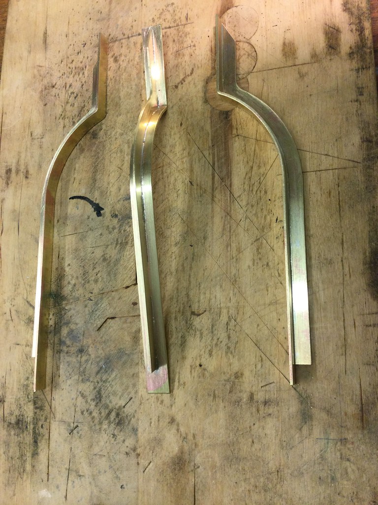 Anyway, I’m very happy with the result, and it is a nice distraction from contemplating the trials still to come… EDIT. It turns out that I've drawn the upper limb of these ribs too long, so they stop exactly at the plate edge. In full size they stop just below the T-section edge beading. Not an issue, because it will be very easy to trim ¼" or whatever off the ends when the time comes. In the meantime the extra length is handy for using the ribs as bending templates. |
|
|
|
Post by simplyloco on Oct 9, 2020 8:10:05 GMT
SNIP Incidentally, I am very agnostic about the recommended gaps for silver soldering that we sometimes hear about. These parts were firmly clamped together, so there was no visible gap at all, yet the solder flowed beautifully from one side to the other all along the joint. So too does flux. Capillary action is like that. I was told at school that the smaller the gap, the better it works, and here is proof. Sure, there is a gap at the molecular level, and that, I think is the point. We don’t need to create a gap in order for silver solder to fill it; the gap is there whatever you do! Hi Gary, very neat indeed, and I agree with you about the gaps! John |
|
|
|
Post by Roger on Oct 9, 2020 16:33:44 GMT
Bringing the story up to date, here is the most recent job on the platework. There are three internal ribs that support the 15xx bunker. The central one is Tee-section, and midway on either side are handed L-sections. On three sides of the plate there are also rivetted butt straps which make the joints... (Thanks to Roger for the photo) I decided early on that the Ts and Ls would be fabricated from flats, not bent up. The ‘spine’ of each of the 3 ribs is necessarily identical, so these were laser-cut in 1.5mm brass in triplicate. (The Adams drawing shows the central rib as having a doubled ‘spine’ but this is clearly incorrect). They are significant because the accurately-cut ribs will form a template for the curve of the bunker top plate itself. (I also decided not to replicate the 'foot' of each rib, as they would interfere with removing the cab unit past the hand pump which will largely hide them anyway.) The ‘face’ (or is it the back?) of each rib was cut from 16g brass strip; ½” wide in the centre, and ⅜” for those on either side. The curving was started in the rolls, but I could only get it approximate and they needed a lot of fine adjustment between fingers and thumb to persuade them to follow the laser-cut profile of the spine. With the big curve finalised, the fold above it could then be carefully marked and very carefully folded. With the ‘face’ strips cut over-long, it was quite simple then to clamp them against the ribs for silver-soldering; they will be finally trimmed to length when the plates they support are ready. So far so good, but this method is neither accurate nor reliable enough for the forming of the curved plate itself! I’m rather dreading that part! I had made four mini-clamps to help with through-drilling rivet holes to all the butt straps and angles that hold the cab together, and although not designed for it, they did most of the ‘holding’ for this bit of silver-soldering too. I enjoy silver soldering (in moderation- I would never build a boiler!), and this went well. As I’ve mentioned earlier, the crispness of the laser-cut edges meant that keeping the ribs square to the base strips was a doddle. The flux paste was not added till after each assembly was clamped up (too messy, and slippery!) Then a number of 1cm lengths of solder wire were spaced out along the length of the joint, as you can see here: The steel wedge is to tilt the assembly a little to stop the melted solder flowing out of the corner. Heat it up, starting at the fold (because it mustn’t move) then move outwards in either direction, don’t let the metal reach red heat. Watch the flux melt first and run into the joint, then the bits of solder melt and flash along the joint in an instant, following the torch; very satisfying. Incidentally, I am very agnostic about the recommended gaps for silver soldering that we sometimes hear about. These parts were firmly clamped together, so there was no visible gap at all, yet the solder flowed beautifully from one side to the other all along the joint. So too does flux. Capillary action is like that. I was told at school that the smaller the gap, the better it works, and here is proof. Sure, there is a gap at the molecular level, and that, I think is the point. We don’t need to create a gap in order for silver solder to fill it; the gap is there whatever you do! Anyway, I’m very happy with the result, and it is a nice distraction from contemplating the trials still to come… Hi Gary, That looks great. Just a couple of things to note about the bunker. Firstly, there are different rivet sizes, depending on where they are. From memory, the 'T' section uses two smaller rivets, presumably because they don't need to be so strong, whereas the 'L' section ones use larger rivets. Don't take my word for any of this, but have a really close look at the many photos I've taken. You will find there are other places where this occurs too. As for counting rivets... They didn't use the same number everywhere when they made the new one! I have pictures of both in that folder. |
|
Gary L
Elder Statesman
Posts: 1,208
|
Post by Gary L on Oct 9, 2020 23:43:31 GMT
Hi Roger
I do believe you are right! -'what sharp sharp eyes you have grandmama!'
I had noticed that the lowest horizontal row of rivets (where the angle connects the cab/bunker to the footplate) has a larger rivet size than the rest of the platework, but I never expected a different size on the bunker ribs, so wasn't looking for it. Even less would I have expected the the two 'mid way' ribs to be different from the central one! The question now is what to do about it...
Our trouble is, we don't have the same range of rivet sizes to choose from as they did in full size. Effectively I can use 3/64", 1/16" or 5/64" equating to ⅜", ½" or ⅝" shank diameter or full-size head diameters of 0.656", 0.872" or 1.096" respectively. Swindon almost certainly were able to size their rivets in 1/16" increments not ⅛" The result is that sometimes we have to use rivets that are a bit too large or a bit too small, thus when adjacent sizes occur in close proximity as here, the difference ends up being visually greater than it should be. (And before anyone asks, no, I totally lack the dedication to turn down hundreds of intermediate size rivet heads!)
As a general principle it is best to err on the small size for models, because paint will enlarge the heads significantly, and a paint meniscus round the base will make them look bigger still.
I am using 1/16" rivets for the row around the cab base, and 3/64" for the others, (and even after trying to scale them on photos that is still largely guesswork). If I go up a size to 1/16" for the bunker 'mid ribs' I wonder if this will make them look unnaturally prominent?
For that matter I wonder what the full-size rivet heads on 1501 actually measure? Has anyone been near them with a calliper? It's a straightforward matter to change sizes at this stage.
Nothing's ever simple is it!
Gary
|
|
dscott
Elder Statesman
Posts: 2,437
|
Post by dscott on Oct 10, 2020 0:03:31 GMT
Is there a SPECIAL PLACE (Apart from on here) that caters for Not only Rivet COUNTERS but also Size of Rivet Measurers?
Do not worry as I now have to own up to spending well over an hour pondering bufferbeam brackets sizes. Trying several.
All drawings done in pencil on layout paper from the master done on card. Measurements added during the session at 20 degrees.
All on A3 for a handy size when in the Workshop Photo Copy's of course!!
Rivets. This is where we can mix and match Metric ones with imperial to our advantage.
David and Lily.
|
|
|
|
Post by Roger on Oct 10, 2020 9:58:21 GMT
I have to confess that I guessed the sizes based on what was available and what looked plausible. I ended up using 0.8mm for the small ones and 1mm for the bigger ones.
|
|
Gary L
Elder Statesman
Posts: 1,208
|
Post by Gary L on Oct 10, 2020 10:00:32 GMT
Yesterday’s job was to drill the rivet holes where the rear bunker plates join the cab side, opening them out slightly to suit 3/64” rivets, and at the same time drilling holes through the ⅜” x 1/16” butt straps that will support the joint. This is a job for those special miniature clamps, and also where the dividing function on the mill DRO comes into its own. It is not too difficult to set up on the milling table, because the vice has been accurately squared on the table, and I can use the side as a guide. However the plates are too large to do all the rows at once; my mill table doesn’t have enough travel on the Y axis.  I suppose I could have had most of the butt straps laser cut including the holes, which would have made work proceed a little quicker, but I didn’t have the confidence that I wouldn't have to make an adjustment to this particular joint if the bends at the rear corners had not worked out as accurately as they did. I shall have to mark each row as it is done, so I can keep track of the rows still to do. I started putting a line of marker pen along the rows as they are finished, but on reflection, I’ll do it the other way round; mark the rows that need doing, and wipe off the marker ink as they are completed. There is little option but to drill them this way, joint-by-joint from the job, especially the holes that fall on a curved surface. It's usually best to drill sheet before shaping,to avoid difficulties supporting the work, but that isn't possible here. It is a minor annoyance that all the 3/64” rivets I possess, from several sources, fail to enter a 3/64” hole, even using a specially-purchased imperial drill. They won’t fit a 1.2mm hole either, even though in theory that is slightly larger than 3/64”. I’ve had to go up to 1.3mm, which is a bit sloppy for my liking. I daresay the shanks will swell to fit when the rivets are set, but this can’t be a new issue can it? I haven’t decided yet whether to set these rivets the old-fashioned way or invest in one of those special tools. The former will be a long and tedious job with difficulties supporting the plates while hammering, the latter involves serious money and it won’t get used again; nor will it reach all the rivet rows anyway. My reservation about a rivetting tool is that I know how easy it is to bend the stem of a copper rivet by smacking it too hard, so isn’t this a risk with a press tool too? I won't be setting any rivets for quite a while, so something more to think about. |
|
Gary L
Elder Statesman
Posts: 1,208
|
Post by Gary L on Oct 10, 2020 12:49:17 GMT
I have to confess that I guessed the sizes based on what was available and what looked plausible. I ended up using 0.8mm for the small ones and 1mm for the bigger ones. Thanks Roger; magnified to 1.5in scale I’m in the same territory as you then. Good enough for me! Gary |
|
Gary L
Elder Statesman
Posts: 1,208
|
Post by Gary L on Oct 11, 2020 0:28:08 GMT
Now for the dreaded bunker upper plate. First step (I think) is to anneal the area to be bent. The brass supplied by MEL is CZ108 half-hard. I don’t know if annealing is strictly needed for the big bend, but it will certainly be needed for the reverse fold, so best do it all at once. However I don’t possess a furnace, and annealing a large flat sheet with a torch, (and it needs a big torch!) is a dicey business if you want the sheet to stay flat. The plate is so big that you inevitably get some parts of it hotter than others, which leads to ripples and waves that are difficult (read impossible) to remove unless you are a highly-skilled metalbasher, which I am definitely not. Annealing only a part of a sheet, while leaving the rest hard, should be a guaranteed recipe for distortion, though at least it reduces the area to be heated to something more manageable. I’ve found you can reduce the distortion a little by shielding the area is not to be annealed with an insulation block. This allows some heat to spread under the block and stay there, so local hotspots are reduced. This method was very successful on the first plate, not so much on this one…  ...but I can live with it. (I’ll have to!) 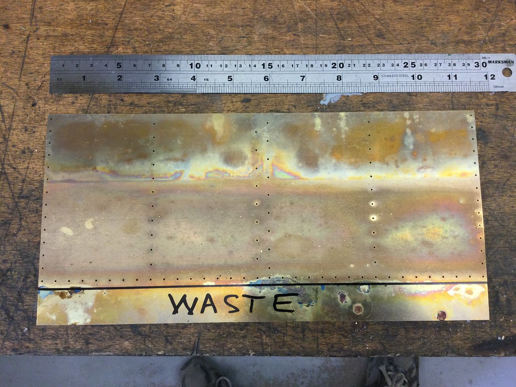 As usual, the annealed area can be seen from the discolouration. The waste strip is even more wrinkly, but I'm not bothered about that- it is only there to aid the passage through the rolls, after which it will -er- go to waste. Thinking ahead a bit, heat distortion might lead to difficulty in applying the edging strips to the cab side aperture. The prototype uses a rolled T-shaped section, rivetted on, but that raises all sorts of questions in model size. My original plan was to clamp and silver-solder a plain 1/4" strip square to the edge, as suggested in the 'simplified' Adams drawing below, but I might need to rethink that. Actually Adams just says "solder," but would soft solder be strong enough? (All suggestions welcome!)... (7/16" width is significantly overscale BTW; the prototype is 2⅛" wide, which scales to 17/64" or a smidge over ¼") There is an edge trim to go on the bunker top too. The prototype uses an unequal Tee section, possible the same as on the cab side, but in this case Adams suggests angle, which might be a better bet, and will help disguise the thickness of the plate... This might be enough to control the ripple in the top edge of this plate, and there is enough area for soft solder to hold it securely, without provoking undue bad effects from heating. (I know the prototype secures all these trims with visible small rivets, but that is a detail step too far for me!) More stuff to think about for the future... |
|
dscott
Elder Statesman
Posts: 2,437
|
Post by dscott on Oct 11, 2020 0:50:53 GMT
Years ago I considered the old Brass curtain rail almost right for 5 inch gauge.
Then another way would be to get a thick brass sheet laser cut in the L or C shape and use small tab and slots along the length.
Steel takes paint better for an exposed surface but brass can and does live with steel without reacting.
Of course this is where CNC comes into its own... Stop dreaming David and get your Denford mini set up.
David and Lily.
|
|
Gary L
Elder Statesman
Posts: 1,208
|
Post by Gary L on Oct 11, 2020 15:50:09 GMT
Years ago I considered the old Brass curtain rail almost right for 5 inch gauge. Then another way would be to get a thick brass sheet laser cut in the L or C shape and use small tab and slots along the length. Steel takes paint better for an exposed surface but brass can and does live with steel without reacting. Of course this is where CNC comes into its own... Stop dreaming David and get your Denford mini set up. David and Lily. Yes, CNC, if only! I've only recently got to grips with 2D CAD, so CNC must wait a day or two  Old brass curtain rail, I'd forgotten all about that stuff! Yes I should think it would have potential in 5" gauge. I had briefly considered steel for the edgings. Brass is fine, and won't rust where the paint gets broken, which it inevitably will round the bunker edge. But when the paint gets chipped, brass glinting through like Donald Trump's bathroom isn't very authentic- in fact that was one of the reasons why I chose steel for the footplate. I shall probably stay with brass, but it isn't an open-and-shut case. Your tab and slot idea is very clever if I understand it correctly; wish I'd thought of that a couple of months ago!! Gary |
|
Gary L
Elder Statesman
Posts: 1,208
|
Post by Gary L on Oct 11, 2020 16:24:18 GMT
I can’t put it off any longer. I’m going to have to feed that part-annealed upper bunker plate into the mangle and try to reproduce the double curvature. To start with I’ve marked the limits of the big curve with felt-tip pen Next, very gingerly, fit it into the rolls, with the rear adjusters set as equal as possible and almost at the ‘no bend’ position; then use the top thumbscrews to grip the sheet between the two front rollers, again, as equally as possible. Not too tight; don’t want to stretch the metal (been there, done that!). Roll it carefully and slowly beween the marked lines, checking always that the sheet stays dead parallel to the rollers, advancing the rear adjusters a quarter-turn for each pass. I really, really don’t want to create a kink or overbend it…  At about ⅓ of the curvature achieved, I took it out of the rolls and reversed it, because I never manage to get an even radius throughout, and I’ve no idea why. Also the grooves at each end of the front rolls are leaving tramlines on the plate, annoyingly, but they can be filled before the job is painted so not a total disaster. As we get nearer the curvature I want, I take the workpiece out more often to check against the template, and sometimes to reverse it again. Near the end, I take it out after every pass. Needless to say this takes several hours… 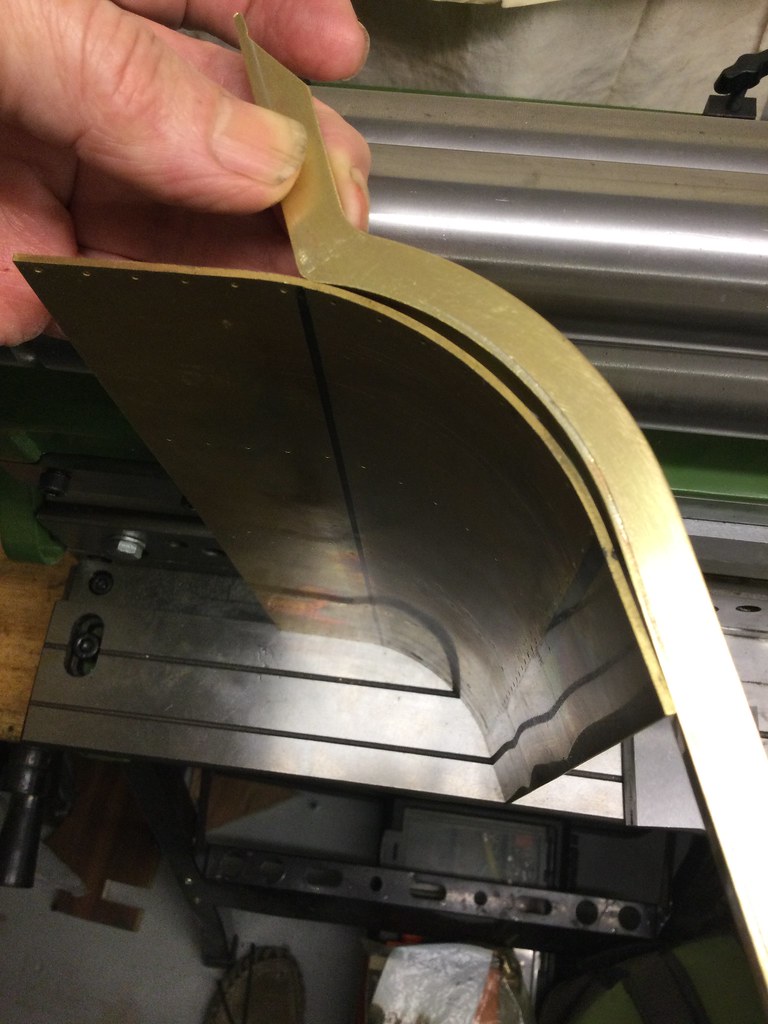 Another hour, taking it very carefully, and I think this is as good as I’m capable of getting...  You might just be able to make out the tramlines. As long as I fill and smooth them before doing the rivetting, they won't be visible after painting. This plate is so solid I can't help but wonder if 1.5mm isn't a touch heavier than it needs to be. We like our model plates to be perfectly flat and smooth, but in full size they soon collect ripples and dings, and they were seldom 'coachwork finish' even when new, at least after the mid 20th Century. That will be my excuse anyway! |
|
|
|
Post by Roger on Oct 11, 2020 18:08:41 GMT
You might consider machining a Vee groove in the back of the tight bend. I knew that I'd never get it tight enough using Steel Sheet, so that's that I did. It guarantees it will bend in the right place and you'll get it much tighter without any difficulty.
|
|
barlowworks
Statesman
Now finished my other projects, Britannia here I come
Posts: 874
|
Post by barlowworks on Oct 11, 2020 19:25:17 GMT
+1 for the V groves, I now use a 90 degree milling cutter for every fold I make, considering my ability to never bend anything in the right place its the best thing I've ever done. Also, keep a permanent black Sharpie in the toolbox to temporarily touch in any glaring brass edges before touching up with a fine brush and paint later (unfortunately, only really works on black). Mike
|
|
Gary L
Elder Statesman
Posts: 1,208
|
Post by Gary L on Oct 11, 2020 23:05:24 GMT
You might consider machining a Vee groove in the back of the tight bend. I knew that I'd never get it tight enough using Steel Sheet, so that's that I did. It guarantees it will bend in the right place and you'll get it much tighter without any difficulty. Yes, the Vee groove is a good trick to get a really tight bend, placed very accurately. I used it for the Toolbox and the Battery Box. Trouble is here though, it isn’t a razor edge bend. It is ⅛” radius inside (acc to the dwgs) or 3/16” on the outer face, so I shall have to use mild trickery to avoid it being too sharp. The bend radius is convenient in one way, because the ribs are bent with a knife finger, which gives a very small radius, say 1/16” nominal inside. Add two thicknesses of 1.5mm brass and you are within a gnat’s crochet of the specified 3/16”. On Speedy of course, it scales to around ⅛” outside, which is getting a bit marginal if your steel is similar thickness to this. Gary |
|