Gary L
Elder Statesman

Posts: 1,208
|
Post by Gary L on Apr 25, 2021 0:16:14 GMT
After a short absence it's back to the workshop to finish preparing the front end plates of the tanks. I had already drilled and countersunk blind holes through the mating parts, to be tapped 8BA for screws to secure the constructional and cosmetic plates together, and at the same time spotted through from the cosmetic plates in way of the handrail and step securing spigots. This is to locate an array of 7/32"dia counterborings to clear the various fixings for these parts that will protrude from the backs of the cosmetic plates. The counterborings will be done with a suitable slot drill. The counterbores don't have to be located to the nearest thou, but better alignment than 'by eye' was desirable. I certainly didn't want to swap between a wiggler and a slot drill for every hole! The solution was to quickly make up a close-fitting pointed cap that slips over the tip of the slot drill: 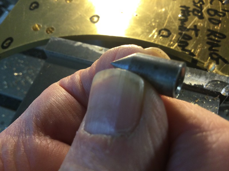 The point is then aligned with the spotted holes by means of the X and Y axis handwheels: 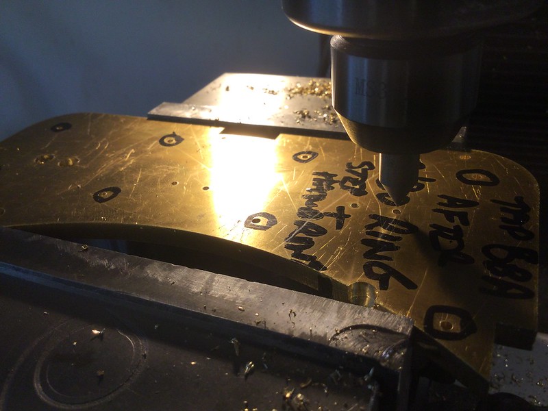 Then slip off the cap and start the slot drill to bore a pre-set depth, which stopped about 1/32" short of breaking through the material:  The idea of all these blind holes is to minimise the amount of leak-stopping that will be needed. The 5mm end plates were then removed from the mill vice and the blind holes tapped 8BA on the bench with a tapping alignment tool that I didn't think to photograph. And then, having successfully gone round 17 holes starting the thread with a second tap, I broke the end off the tap in the very last hole... grrr! Needless to say, it snapped off below the surface, and couldn't be coaxed out with a scriber point, so into the Alum bath it had to go. Alum is a really useful substance for this sort of rescue. I couldn't resist this photo, taken about an hour after immersion in the bath, and already the tap tip has turned black and you can see the stream of very fine bubbles rising from the hole like a mini-volcano:  A day or two of immersion should see all traces of the tap dissolved away by the alum, which is otherwise non-corrosive and (as far as I know) not particularly poisonous either. I got mine from eBay for a couple of quid, you just dissolve the crystals to get a saturated solution and keep the solution in a plastic jar ready to deal with the next broken tap. Or drill (as long as it is not carbide  )... |
|
Gary L
Elder Statesman
Posts: 1,208
|
Post by Gary L on Apr 25, 2021 22:38:24 GMT
... and just for the record, 24 hours later and all that remains of the tap tip is a residue of fine black powder. I've been out all day, so it might have taken much less time than that. Obviously a bigger tap would take longer, but we never break the big ones, do we?  Gary |
|
dscott
Elder Statesman
Posts: 2,437
|
Post by dscott on Apr 25, 2021 23:27:18 GMT
I cheated with my 2 days with an 8 BA tap by drilling most of the buffer beam out as well. Having re designed most of the 2 F Dock Tanks frames. I decided upon fake bolts so these just needed a bit of thread. 4 of the rivet holes wandered so this became the rear beam which gets covered by a bit of angle. Just to complete the illusion I even fitted dummy rivets on the inside bunker fixing angle. No one will ever know!!  Getting back to 1500's this little bit of clearance came up in my collection. Fancy fitting a thicker gasket than usual and hearing a strange knocking. A bit of overtime with a half round file.  Quite a stretch at maximum the other way. No wonder it has an oil box or two above the link. David and Lily. |
|
|
|
Post by ettingtonliam on Apr 26, 2021 15:49:06 GMT
... and just for the record, 24 hours later and all that remains of the tap tip is a residue of fine black powder. I've been out all day, so it might have taken much less time than that. Obviously a bigger tap would take longer, but we never break the big ones, do we? Gary Oh yes we do! Or I do anyway. |
|
|
|
Post by keith1500 on Apr 26, 2021 21:09:15 GMT
I cheated with my 2 days with an 8 BA tap by drilling most of the buffer beam out as well. Having re designed most of the 2 F Dock Tanks frames. I decided upon fake bolts so these just needed a bit of thread. 4 of the rivet holes wandered so this became the rear beam which gets covered by a bit of angle. Just to complete the illusion I even fitted dummy rivets on the inside bunker fixing angle. No one will ever know!! Getting back to 1500's this little bit of clearance came up in my collection. Fancy fitting a thicker gasket than usual and hearing a strange knocking. A bit of overtime with a half round file. Quite a stretch at maximum the other way. No wonder it has an oil box or two above the link. David and Lily. Wow, what an incredible couple of photos. Not knowing too much about Walschaerts valve gear I would have expected the Union link to be almost horizontal but clearly here it is uphill. Was that dictated by the combination levers dimensions I wonder. |
|
|
|
Post by ettingtonliam on Apr 26, 2021 22:36:27 GMT
The upper rod has all the signs of being adjusted for length by the traditional method of 'fullering' (heat the middle of the rod to red heat, then belt with a sledge hammer to stretch it. Careful smiths could avoid leaving those tell tale bruises.
|
|
dscott
Elder Statesman
Posts: 2,437
|
Post by dscott on Apr 26, 2021 23:38:17 GMT
Roger now takes his carefully made and superbly polished rod off his 1501 and carefully bashes 11 bangs into the middle.
Now we cant tell the two apart!
Must check on the other side!
David and Lily.
|
|
Gary L
Elder Statesman
Posts: 1,208
|
Post by Gary L on Apr 29, 2021 0:05:23 GMT
Another odd job on the LH tank frame is to make the arrangements for attaching the water valve. So accurate coordinates were taken, to suit the already-drilled hole in the Spectacle Plate for the handle spindle and the scale distance from the cab front; then bore it in the mill and tap ⅜" x 32. I had already silver-soldered a swelling piece on the side of the lower strake, otherwise the hole would have cut the edge of the strake, which wouldn't be clever... 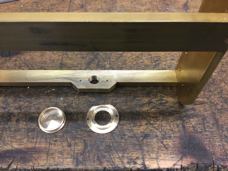 In the picture you can see the tapped hole, and the top cap and bottom flange respectively for a strainer, both turned from 1" dia brass. Then the necessary holes were drilled and tapped for a pair of 10BA RH brass screws. The main hole is a bit close to the tank inner side, so the mounting flange has a flat milled on one side, and the 10BA holes are off-centre to the main hole. (It's lucky the tank inner sides are vertical here, not concave!) Next, a piece of bronze (or is it copper?) gauze 2" high was rolled, then painted with solder paint top and bottom and along the vertical seam:  Three lengths of copper wire (extracted from some electrical cable) were then wrapped round to hold the gauze in place while the whole thing was sweated together with a soft flame. If the wire had soldered itself to the gauze in a few places it wouldn't matter, but in the event each piece peeled off leaving scarcely a trace. So here is the final assembly:  As you can see, the valve is a standard off-the-shelf item (with a cylindrical PTFE valve core). It doesn't resemble the prototype very much at all, but it has a certain honesty about it. Since the injector is a standard off-the-shelf item as well (Sorry Roger and Adam, but my life's too short already!) there isn't a lot of point in spending loads of time making a super-accurate model valve. If I feel the need to upgrade both items later, it will be a straightforward replacement job; though even then, a second injector and valve would be needed for appearance, and the valve could only be a dummy, because in the position required ( inboard of the valve shown), there is no way of connecting it to the water space. I will have two injectors BTW, but the second one (on the RH side) will feed only from the auxiliary tank on the driving trolley. PS. David, I love the idea of Roger bashing 11 bruises into his radius rod in his relentless pursuit of accuracy!  Me, I'm a bit of an expert bruise-basher if anybody needs any tips...  |
|
|
|
Post by johnboy on May 4, 2021 13:38:29 GMT
Another odd job on the LH tank frame is to make the arrangements for attaching the water valve. So accurate coordinates were taken, to suit the already-drilled hole in the Spectacle Plate for the handle spindle and the scale distance from the cab front; then bore it in the mill and tap ⅜" x 32. I had already silver-soldered a swelling piece on the side of the lower strake, otherwise the hole would have cut the edge of the strake, which wouldn't be clever... In the picture you can see the tapped hole, and the top cap and bottom flange respectively for a strainer, both turned from 1" dia brass. Then the necessary holes were drilled and tapped for a pair of 10BA RH brass screws. The main hole is a bit close to the tank inner side, so the mounting flange has a flat milled on one side, and the 10BA holes are off-centre to the main hole. (It's lucky the tank inner sides are vertical here, not concave!) Next, a piece of bronze (or is it copper?) gauze 2" high was rolled, then painted with solder paint top and bottom and along the vertical seam: Three lengths of copper wire (extracted from some electrical cable) were then wrapped round to hold the gauze in place while the whole thing was sweated together with a soft flame. If the wire had soldered itself to the gauze in a few places it wouldn't matter, but in the event each piece peeled off leaving scarcely a trace. So here is the final assembly: As you can see, the valve is a standard off-the-shelf item (with a cylindrical PTFE valve core). It doesn't resemble the prototype very much at all, but it has a certain honesty about it. Since the injector is a standard off-the-shelf item as well (Sorry Roger and Adam, but my life's too short already!) there isn't a lot of point in spending loads of time making a super-accurate model valve. If I feel the need to upgrade both items later, it will be a straightforward replacement job; though even then, a second injector and valve would be needed for appearance, and the valve could only be a dummy, because in the position required ( inboard of the valve shown), there is no way of connecting it to the water space. I will have two injectors BTW, but the second one (on the RH side) will feed only from the auxiliary tank on the driving trolley. PS. David, I love the idea of Roger bashing 11 bruises into his radius rod in his relentless pursuit of accuracy! Me, I'm a bit of an expert bruise-basher if anybody needs any tips... |
|
|
|
Post by johnboy on May 4, 2021 15:39:30 GMT
Hi just to introduce myself - My Name is John Bright and I'm now the new proud owner of Barry Leach's Paddington and look forward to learning lots from you guys on completing this Loco. Barry's engineering skills were exceptional, and it's going to be quite a challenge for me to complete this bearing in mind my last loco was a simplex but I'm thoroughly looking forward to the Challenge and the learning curve!. I received the loco in boxes of many parts which I'm certain will result in a fully running rolling chassis although the cylinders have not as yet ever been fitted to the mainframes - so plenty of work to do !
|
|
JonL
Elder Statesman
WWSME (Wiltshire)
Posts: 2,906
|
Post by JonL on May 4, 2021 17:32:34 GMT
Hi just to introduce myself - My Name is John Bright and I'm now the new proud owner of Barry Leach's Paddington and look forward to learning lots from you guys on completing this Loco. Barry's engineering skills were exceptional, and it's going to be quite a challenge for me to complete this bearing in mind my last loco was a simplex but I'm thoroughly looking forward to the Challenge and the learning curve!. I received the loco in boxes of many parts which I'm certain will result in a fully running rolling chassis although the cylinders have not as yet ever been fitted to the mainframes - so plenty of work to do ! It sounds like it needs a build thread of its own to do it justice, if you start one in the general chat section I'd love to see how it stands. |
|
Gary L
Elder Statesman
Posts: 1,208
|
Post by Gary L on May 4, 2021 22:46:33 GMT
Hi just to introduce myself - My Name is John Bright and I'm now the new proud owner of Barry Leach's Paddington and look forward to learning lots from you guys on completing this Loco. Barry's engineering skills were exceptional, and it's going to be quite a challenge for me to complete this bearing in mind my last loco was a simplex but I'm thoroughly looking forward to the Challenge and the learning curve!. I received the loco in boxes of many parts which I'm certain will result in a fully running rolling chassis although the cylinders have not as yet ever been fitted to the mainframes - so plenty of work to do ! It sounds like it needs a build thread of its own to do it justice, if you start one in the general chat section I'd love to see how it stands. Hi John You are very lucky to have acquired Barry’s Paddington. He was indeed exceptional and exacting, and you have every reason to be proud of it; you need have no anxieties about the quality of his workmanship, visible or not. The cylinders are the only items he did not make, and are the culmination of a very long and troublesome story; I do not know if Barry ever actually saw them before he died. We were working more or less in parallel for a couple of years, and Barry gave me a great deal of useful advice and encouragement. The lockdown has meant my Paddington has drawn well ahead of where Barry was, but that isn’t a problem. I agree wth Nobbysideways, it would be great if you started a build thread about yours. Have no fears about duplication; this one of mine started with all the mechanical and boiler work finished, so there are a great many gaps that people will be keen to read about. There are also at least two members in the process of building a 5” gauge Speedy (to a standard that LBSC could only dream of) and others who have driven or maintained 1501 at the SVR, so you will find there is a great deal of support and information available here, and you only need ask. And you will ask! Paddington is a fine loco, but the best advice you will ever get is “don’t trust the drawings!” And the second best advice is “check every dimension twice!” Barry had a set of digital copies of the Swindon drawings, which hopefully have been bequeathed to you; they will help you resolve lots of uncertainties. So good luck, and I hope to see lots more of your build! Gary |
|
Gary L
Elder Statesman
Posts: 1,208
|
Post by Gary L on May 6, 2021 23:50:04 GMT
With most of the detail and accessories now complete, there is no way of avoiding the task of attaching the skins to the tank frames. This should be the "beginning of the end" of the project, but it is going to be a long and tedious grind. I'm not sure if the Adams design is the best way, but I've never done anything like this before, so it makes sense to follow the instructions when you know no better. Essentially there are two outer skins on each side (top and bottom with a single bend in each) plus two removable access covers (barrel and firebox) on the inboard face of each tank. These inner panels have to be removable to get at all the fastenings of the fittings, and to the water outlet strainer. The drawings show these access covers with tapped holes ¾" apart all around every edge of all four, and that's a heck of a lot of holes! And that's before we even consider how the outer skins will be attached*.. So a long and tedious job is in store. I've decided to tackle the smallest and easiest panels first; these are the flat, vertical and almost square access covers that face the firebox sides. Note to self: in the highly unlikely event of doing anything like this again, make sure the supplier can guillotine all the edges! Many of the plates I had acquired were sawn, not guillotined, and my mill table has insufficient travel for the long edges, so the first job was to true up at least one long edge each by hand, with file and straightedge:  The important thing is level off all the peaks. A few valleys don't matter, because except for the two smallest panels, none of the long edges can be cut to size until after all the bending is done. The short edges though, need to be parallel and accurately finish-sized. This will greatly help the bender, and would be very difficult to do after the bending is complete. So if one edge is made regular enough to use as a datum for milling the two adjacent edges square to it, that is all that matters. With a decent straightedge and the light behind it, the valleys show up as a bright gap, and the peaks cause the straightedge to rock. So the procedure is, find the peaks, mark with a felt-tip, attack with a file, then find the next peak to attack and so on. Once you have the straightedge in contact with -say- 60% of the length of the edge it is good enough for the next step which is...  Butt the straightened edge up to a guide bar, (centre left in the photo) which is bolted to the table, accurately square to the longest axis of the mill. Then run an endmill along the first edge to be squared, turn the plate around and (obviously) still using the straightened edge as a datum, run the endmill along the second edge, with enough passes to get it to length. I found it was best to clamp two paired plates together for this second edge, so even if the distance is not quite right, at least they are wrong by the same amount. Once the distance exceeds the length of your longest calliper, it is no longer easy to measure to the nearest thou. There are workarounds involving clamping the calliper to an extension bar, but that sort of precision is probably OTT for a pair of Pannier Tanks. I found I could attach one of my mini-clamps to the aluminium straightedge and use that as a gauge from the tank frame, since fitting that is the most important criterion. I doubt if the measurements transferred in this way were more than 0.005" out. Guillotined stock would have spared the effort of straightening the first long edge, but you still can't be certain the other edges will be exactly square, and certainly not to exactly the right length, so this squaring-off operation is probably unavoidable. Also, an edge that has been guillotined is never cleanly square-cut, so removing a few thou in the mill is usually beneficial anyway. So that's the plates ready for bending, which will happen next week. To pass the time (!) I can make a start on drilling and tapping 6BA for the cover screws. Equipped with a DRO, it is not necessary to 'spot through' every hole in the traditional way, because (with the aid of the dividing function) the machine will accurately repeat any measurement any number of times in any quantity; all that is necessary is to make sure the work is mounted accurately each time. This means that some of the frame bars can be unscrewed and drilled side-by-side in pairs or fours as shown, which helps prevent gross errors...  -But it doesn't make the job any less tedious and boring! The holes are blind, 2.3mm dia (6BA tapping) and ⅜" deep for ¼" RH screws. It's a case of "move along, nothing to see here!" I'll carry on all this drilling and tapping in the background, without adding to this diary until there is something more interesting to report! See you in a week or two's time!
*Footnote. David Adams shows the outer skins also attached by small (8BA) CSK screws at ¾" intervals along every edge. He suggests through-drilling them, and nutting the screws on the inside, then sealing them and filing the screwheads flush to finish off. That's an exceedingly long-winded job, and not an especially tidy one. I would prefer to tap the holes and avoid all those nuts on the inside, but that will make the task insanely long, and how many broken taps would need extracting?? I'm not convinced that a fastening is needed every ¾", specially for the outer skins which are to be permanently fixed in place. Also, some form of hammer-in rivet would surely be simpler, if such things exist in this small size and in non-ferrous material? Could the job be done by soldering, with wire and clamps and just a minimum number of screws to maintain position? Or would this just be an invitation to get banana-shaped tanks?? |
|
|
|
Post by johnboy on May 7, 2021 9:31:50 GMT
Gary
Thanks for your comments - I've worked out that Barry definitely saw his cylinders as I think the last thing he was doing was fitting the valve crosshead guides.
I would really appreciate it if you could let me know Barry's user name on this site as I would like to read his posts to get me up to speed on his contribution - I'm in the process o trying to secure his CAD drawings as part of this project so I can share them on this community. I will also setup a new thread in respect of his work on the Paddington regards John
|
|
Gary L
Elder Statesman
Posts: 1,208
|
Post by Gary L on May 7, 2021 18:21:22 GMT
Gary Thanks for your comments - I've worked out that Barry definitely saw his cylinders as I think the last thing he was doing was fitting the valve crosshead guides. I would really appreciate it if you could let me know Barry's user name on this site as I would like to read his posts to get me up to speed on his contribution - I'm in the process o trying to secure his CAD drawings as part of this project so I can share them on this community. I will also setup a new thread in respect of his work on the Paddington regards John Hi John Barry was never a member here, so that is a blind alley I’m afraid. He was however, at the time of his passing, Chairman of Cheltenham SME, so if you make contact with them, someone might be able to help. I do have WIP copies of some of his CAD work, but mostly only as PDF because at the time that was all I could read. You will have come across his Paddington pages on the CSME website by now I expect? www.cheltsme.org.uk/index-paddington_project.htmlHTH Gary |
|
|
|
Post by martyn1936 on May 8, 2021 15:35:19 GMT
Hello, my name is Martyn Harrold and I too have inherited a part built Paddington that was being built by Peter Breakwell of the Guildford club. Peter was a fine engineer and I will struggle to match is standards. I have been following our thread for a while now and it has given me the confidence to finish the engine. I have now got to the stage of having an air running chassis and am about to start on the boiler backhead and fittings. However the only drawings I have are those produced by David Adams. Can anyone guide me to where I get some more information. I know that I will have to go to the Severn Valley Railway this year to hopefully take some photographs of the original.
Thank you Gary for the thread, it has been so helpful, I have used the information you have posted to buy the tank materials from MEL and all of the other bits drawn by you.
|
|
Gary L
Elder Statesman
Posts: 1,208
|
Post by Gary L on May 8, 2021 23:47:00 GMT
Hello, my name is Martyn Harrold and I too have inherited a part built Paddington that was being built by Peter Breakwell of the Guildford club. Peter was a fine engineer and I will struggle to match is standards. I have been following our thread for a while now and it has given me the confidence to finish the engine. I have now got to the stage of having an air running chassis and am about to start on the boiler backhead and fittings. However the only drawings I have are those produced by David Adams. Can anyone guide me to where I get some more information. I know that I will have to go to the Severn Valley Railway this year to hopefully take some photographs of the original. Thank you Gary for the thread, it has been so helpful, I have used the information you have posted to buy the tank materials from MEL and all of the other bits drawn by you. Welcome to the Forum Martyn! For a long time I harboured the suspicion that Barry Leach and I were the only Paddington builders left in the world, so I'm delighted to be finding that was far from the case! My abiding regret is that Barry's project pages on the CSME website (which are almost entirely about drawing errors) will never be finished, but they are an invaluable source of information for Paddington builders in the first half of the project at least. WRT photos at the SVR, Roger Froude of this parish has taken a huge number, and many of them have featured in his long-running "Help with Speedy Valve Gear..." thread. At 700-odd pages it is no longer a quick read, but the detail and accuracy he is including exceeds that of Paddington in many respects, so it is an essential and very instructive source of information. He is very generous with his time and his research and is an all-round good sort, so I'm sure if there are particular aspects where a photo would help you, a PM to him will bring forth enlightenment. Drawings are more of an issue because of copyright, but the GWS at Didcot are the most accessible source. I hope the MEL files will do the job for you. They were not drawn for public sale of course, and they were intended to improve on, not replicate the Adams design; and in certain respects they reflect my particular needs and boiler dimensions which might not suit everyone. Inevitably there are errors too, and one day I will send corrections to Ed but I haven't got around to redrawing them yet. The main uncorrected errors are in the Pannier Tank framing and all can be corrected by milling away superfluous metal, so they are inconvenient rather than disastrous. I hope you will do as I suggested to Johnboy and start your own build thread on here. Some loco designs have featured in numerous threads, but there was nothing at all on Paddington until I started mine, so there is plenty of room for more... especially as my thread starts from a fairly late point in the build, so there is a yawning unfilled gap. Good luck-and best wishes Gary |
|
Gary L
Elder Statesman
Posts: 1,208
|
Post by Gary L on May 13, 2021 23:29:52 GMT
Still making slow progress on the tanks, despite many distractions (and it's not hard to be distracted from all this boring drilling!) The support bars for the rear access plate have all been drilled and tapped at ¾" intervals, and reinserted into the tank framework. Next step was to drill all round the edges of the plates themselves- much easier, because the material is thin (18swg) and there is nothing to be tapped. Also the plates could be drilled clamped together, so half the work. The division function on the DRO made sure that the array of holes were square to each other and accurately spaced, with no need for marking out or 'spotting through':  But these are the smallest plates in the tanks, and they only just fitted on the table of the mill. It is necessary to remove and replace one clamp at a time in sequence, to get access for the drill all round without allowing the plates to move. Anyway, it all worked out very well. The plates are interchangeable and fit in any orientation; not that that is exactly a huge benefit as they are out of sight and will only be opened up once every blue moon, but satisfying nonetheless:  All the remaining plates have to be bent before they can be drilled, and their size and awkwardness will mean a different technique will needed. But the bending is the next job, so look out for the next thrilling instalment! |
|
Gary L
Elder Statesman
Posts: 1,208
|
Post by Gary L on May 14, 2021 23:59:38 GMT
I must be Really Lucky. Paul is a friend of a friend and a retired die maker (die as in the machines that cut out gaskets, cardboard boxes etc) as well as a steam nut with a Sentinel steam lorry and a Stanley steam car undergoing extensive overhaul. Anyway Paul was 'volunteered' to help me with those bends in the pannier tank skins that have kept me awake at nights wondering how on earth to get a smooth and accurate bend in expensive brass plates, and this post tells you how he achieved it. Being very painstaking he devoted an entire morning doing it, not to mention previously preparing the jig, so this post is by way of a message of gratitude. (And before you ask, please don't... I won't reveal his whereabouts even under torture!) So first, here is the set-up, with a spare piece of plate being used to calibrate the bend:  In essence it is a length of steel channel, just wide enough to accommodate a steel pipe of slightly less than the required bend radius, plus the thickness of the brass. The internal corners of the channel are well rounded, and it is set into a wooden jig, the main purpose of which is to hold two adjustable stops (marked A in the photo.) The second one in brackets (A) is concealed behind the test plate. B indicates a bit of sponge rubber at each end of the pipe and C marks a pair of stout steel U-straps, the purpose of which is to make sure the pipe stays aligned with the channel. (The U-strap nearest the camera is out of position). Here is a closer look at the jig before placing it under the two presses:  The test plate in the previous photo is used to position the stops so the bend will be at exactly the right distance from the long edge of the sheet, and Paul is fine-tuning the settings so that the bend will be exactly parallel to the prepared edge of the brass. Now the jig goes back under the presses, with the addition of some thin (black) plastic sheet which will protect the surface of the brass from scuffing on the edges of the steel channel:  Then, the presses are worked in unison to get an even bend. Note the extra square bar between the presses and the pipe to give a little more rigidity. Paul made the bends in stages, checking on positioning and bend angle at every step. "It is much easier to bend a little more than take it away if you bend too much"
 Even with the massive pipe and the backup square section, there is some flexing between the rams of the presses; that is what causes the slight bowing in the upstanding edge of the brass plate. It can be compensated at the end of the process by pressing at the middle of the bend length. Finally here are two of the four bent plates loosely arranged around one of the frames so you can get a foretaste of the end result. The other (unclothed) tank frame is standing on the right: 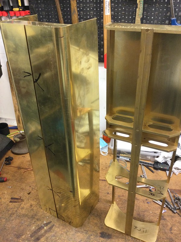 David Adams specifies 16swg for the brass, but I used 18swg and the laser-cut frames were very slightly enlarged to compensate for the small reduction in thickness. I see no need for skins as thick as 16swg, and it would make the bending process that bit harder. The small difference in thickness helps compensate for springback and makes it more likely that a stock size of pipe will suffice to form the bends. The prototype tanks are good, but far from perfectly flat, so I'm not concerned about any slight rippling (not that there is any to see, or not yet). This by the way, is the reason why there are three intermediate bulkheads in my redesign, not two as in the Adams design. The prototype tanks have two intermediate bulkheads equally spaced, and show through the skins very noticeably, emphasised by the prominent welded seams. (Far from the 'hungry dog' look of a modern warship, but noticeable nonetheless): That could occur at the soldering stage of the model tank assembly, in which case the Adams spacing will show up as 'wrong'. This is because the second bulkhead from the rear (i.e top, in the frames photo) is necessary to form the 'step' in way of the firebox, but it isn't at the exact third length from the rear. My solution is to cut away the outside of that bulkhead so it doesn't touch the outer skin, and to insert an additional bulkhead that does, an inch or so to the rear. You can see the modified profile in the frames photo. |
|
|
|
Post by coniston on May 15, 2021 17:23:13 GMT
You are a lucky chap Gary, I bet that's a weight off your mind and you can sleep easy now? Chris D |
|


 )...
)...


 Me, I'm a bit of an expert bruise-basher if anybody needs any tips...


