Gary L
Elder Statesman

Posts: 1,208
|
Post by Gary L on Jan 7, 2022 0:00:36 GMT
The perfect time to do it then! You don't want your lovely clean brass tanks covered in oven gunge, do you? Good luck Reg Hi Reg Impeccable logic. How could she resist! But on a more serious note, building your tender that way, you must have either used solder paint, or else pre-tinned all the mating surfaces. Did you ever find a need to add solder to any joints after the baking operation? Have you any tips for a novice? Gary |
|
|
|
Post by suctionhose on Jan 7, 2022 4:15:10 GMT
Good one Reg! Keep brilliant ideas like that coming and those engines will finished in no time!
Actually a mate called today asking about drying paint in the oven while his wife's at work. I said "Sure. Just think of that oven as another machine tool. Showed him your pics!
Just soldered a tank up myself this week - outside in the open..
Wasn't there a song "Soldering in the Rain"? (might have been singing, can't remember..)
Anyway, like Gary, I love to hear a few more details..
|
|
|
|
Post by RGR 60130 on Jan 7, 2022 9:35:19 GMT
The oven was used to get the assemblies up to soldering temperature before any solder was applied. After that I used a small DIY type blow torch as I went round the joints applying the solder on one side and the heat on the other to draw the solder through. With the heat in the job from the oven there was no distortion and the solder melted pretty much as soon as the flame was applied. I had the sole plate bolted to the basic chassis which gave a bit more thermal mass and helped prevent any distortion too. From memory the stages were: Sole plate with wheel splashers Rear deck assembly Main body Middle of coal chute Sides of coal chute Locker tops and front edge beading. I used resin cored solder for these without any pre-heating in the oven and the adjacent joints were fine. After each stage it was given a good scrub in hot soapy water then rinsed off (easier to do in the bath / shower)  DSC01952 DSC01952 by reg.rossiter, on Flickr  DSC01958 DSC01958 by reg.rossiter, on Flickr I should have a Word document somewhere that I started writing as a set of build instructions for future reference. I'll have to try and find it. Reg |
|
|
|
Post by suctionhose on Jan 7, 2022 10:32:23 GMT
Hi Reg,
Soldering in the kitchen? Sounds like a good process. I was going to use the gas bbq for general heat but have found it a bit hard to control.
Don't worry about the word doc, go microwave some valve gear instead...
|
|
|
|
Post by RGR 60130 on Jan 7, 2022 11:02:37 GMT
Hi Reg, Soldering in the kitchen? Sounds like a good process. I was going to use the gas bbq for general heat but have found it a bit hard to control. Don't worry about the word doc, go microwave some valve gear instead... Even I draw the line at doing the actual soldering in the kitchen! My workshop is what would normally be a dining room but all hot work is done in the garage, shed or outdoors. Electric fan ovens are a useful bit of kit but I'm struggling for alternative uses for the microwave 🙁 My apologies to Gary for spamming has thread. Reg |
|
Gary L
Elder Statesman
Posts: 1,208
|
Post by Gary L on Jan 7, 2022 12:56:22 GMT
No worries Reg, it is all relevant! Thanks for the info, your tender looks really excellent.
Gary
|
|
Gary L
Elder Statesman
Posts: 1,208
|
Post by Gary L on Jan 8, 2022 21:31:24 GMT
Today was the first Big Day and I have soldered up the first (the LH) Pannier Tank.It took 2 hours to paint all the mating surfaces with solder paint and screw everything together (less than expected), then a further hour to bring everything up to temperature, and then go over the seams with solder wire just to be on the safe side. (And gain a couple of small blisters on my fingers!). It used up about ⅔ of a tinlet of solder paint, which is also less than I expected. (I have another in reserve, which I will need for the second tank) Here is the tank fitted into the pre-warmed firebrick trough, just before I lit the torch again to melt the solder paint:  During the heat, I had to turn the tank onto its top then its bottom to run extra solder into all the external joints, and then onto its back to run some solder into the longitudinal joint, so the hearth ended up a lot less tidy than this, but by that time everything was more or less at the same temperature, including the bricks. I left the tank on its back to cool down, with the bricks closed up, covered with a blanket, and it took 2 hours to cool to hand heat. It didn't look so pretty when the soldering was finished, but as I said before, nobody will see the inside of the tanks, and the outside will be covered in paint, so if it isn't distorted and doesn't leak I will be happy. Here it is before scrubbing, complete with black flux stains:  But most of the black washed off with warm water, and most of the rest just needed some washing-up soap and a stiff bristle brush:  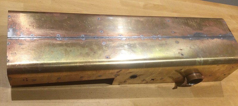 Everything looks straight and fair, and there are no obvious leaks, so tomorrow I will file down the screw heads and give it a general clean up. |
|
|
|
Post by andyhigham on Jan 8, 2022 22:40:10 GMT
I wonder how much easier it would have been to just form the outer skin and TIG weld it together?
|
|
Gary L
Elder Statesman
Posts: 1,208
|
Post by Gary L on Jan 8, 2022 23:56:24 GMT
I wonder how much easier it would have been to just form the outer skin and TIG weld it together? I have often thought that Andy, believe me! However I would not have had the skill to do it and guarantee no lozenging or twisting during the welding operations. Also, perhaps more important, the Adams framework allows for the complete inner face of each tank to be removable. I don't think this would be needed very often, but various fittings require access from inside to secure them, not least the filter for the injector feed, the handrails, and the bolts for the cross-girders. Also bear in mind the shape is not a simple box like LBSC’s Speedy, but there is a step in the back and a change of profile forward of the firebox. Not impossible (after all the prototype was frameless) but a significant extra difficulty. The tanks on my Speedy were built with 'stressed skin' (not by me) as I think were Roger's. ISTR that one of mine was not completely square. There was also a significant difficulty of access inside, and the threads for the cross-girders (which necessarily had to be tapped into the brass skin) were very weak and at least one stripped. So although the construction has been laborious (and there is still more to do) the tanks will be massively strong, and so will the anchorages. Finally, I wanted this series to be helpful to builders of average skill, like me, so I am satisfied this was the best way to do it. Others are free to do it differently! Gary |
|
Gary L
Elder Statesman
Posts: 1,208
|
Post by Gary L on Jan 10, 2022 23:54:05 GMT
Still waiting for the extra solder sticks of 40/60 to arrive, so spent the workshop time in giving the soldered tank a light linishing followed by a file to remove the protruding screw heads. This close-up photo might be instructive:  In the photo you can see the gap of about 1-2mm between the two plates, which will be filled with 40/60 when it arrives. Now that the whole tank is securely soldered together, I don't think a bit of local heat will cause any problems, I shall take care to keep it to a minimum. Note how most of the protruding screw heads alongside the central gap have disappeared entirely, or there is a a very shallow vestigial slot visible. Those will be easily filled with knifing filler during painting if I don't fill them with solder first. There are shallow dimples in other places though; only a thou or two deep, if that, but too deep to cover by filing away any more skin. They show up clearly now, because of the texture change in areas reached by the file, and left untreated they will definitely show through the paint. A skim of solder will level them up; nothing to be concerned about, but I think it is a result of putting a last tweak on the screwdriver when screwing them down. On the second tank I shall just screw them finger-tight, and see if that makes any difference. On a close examination inside, there are places on the fore and aft corner radii where the solder looks a bit gappy, even though it didn't seem to leak, so those places too will get some extra solder for insurance, with a bit of local heat. (It is very like descriptions of boiler making, though at a much lower temperature of course.) There is one more matter to deal with before the reheat, and that is the vertical through-tubes (not photographed, sorry). These foul the radiused inner tank covers by about 1/16", no more, but enough to make fitting the covers awkward, despite there being just enough spring in the covers to allow them to be screwed home. I need to decide whether to locally flatten the tubes, or to try and make a suitable trough in the cover to accommodate them. The first is easy, but will be visible from above; the second is better, but I doubt my panel-beating skills. I'll sleep on it. |
|
|
|
Post by martyn1936 on Jan 11, 2022 15:29:59 GMT
Well done Gary. I'm glad that you are ahead of me and that you are sharing your thoughts as you go as they are a bit daunting when you first look at the various ways of putting them together.
Going back to your Brake valve, I have looked at the CRO website and he is not making them at the moment as he has some catching up to do so time to think. You mentioned that you modified his valve to provide some lap. Did you buy his finished valve or his castings? I plan to have a vacuum ejector as well as a steam brake and want them to operate sequentially. Is that what you meant by lap?
I am tempted to buy a machined valve from CRO as I want to finish my loco and time is becoming important. Is there anything I need to know?
Going back to the displacement lubricator I am still not 100% clear how they work as they have 100 psi across them when the loco is coasting and very much less when the engine is working hard. With little pressure drop across them then is it enough to overcome a spring loaded check valve? I intend to make a vertical check valve but what is a "light" spring as shown on the drawings.
I have gone for a 1mm hole in the nozzles but have made a few other sizes so that I can experiment and have made a tool to remove them as I intend to glue them in with Nutlock.
Thanks again for the inspiration and to Roger and others for the information they freely provide on this site.
I need all the help I can get.
Martyn
|
|
Gary L
Elder Statesman
Posts: 1,208
|
Post by Gary L on Jan 11, 2022 16:45:26 GMT
Well done Gary. I'm glad that you are ahead of me and that you are sharing your thoughts as you go as they are a bit daunting when you first look at the various ways of putting them together. Going back to your Brake valve, I have looked at the CRO website and he is not making them at the moment as he has some catching up to do so time to think. You mentioned that you modified his valve to provide some lap. Did you buy his finished valve or his castings? I plan to have a vacuum ejector as well as a steam brake and want them to operate sequentially. Is that what you meant by lap? I am tempted to buy a machined valve from CRO as I want to finish my loco and time is becoming important. Is there anything I need to know? Going back to the displacement lubricator I am still not 100% clear how they work as they have 100 psi across them when the loco is coasting and very much less when the engine is working hard. With little pressure drop across them then is it enough to overcome a spring loaded check valve? I intend to make a vertical check valve but what is a "light" spring as shown on the drawings. I have gone for a 1mm hole in the nozzles but have made a few other sizes so that I can experiment and have made a tool to remove them as I intend to glue them in with Nutlock. Thanks again for the inspiration and to Roger and others for the information they freely provide on this site. I need all the help I can get. Martyn Hi Martyn I bought castings from Adam Cro, and then adapted them to my needs. 'Lap' is a vac valve mid-position where the train pipe is blanked off from the ejector; thus you avoid the situation where you have reduced the vacuum partially for a controlled speed reduction, but the ejector is still exhausting the system, so your brake application becomes unpredictable. There is a link to a better explanation on Station Road Steam's website where they cover mods to their Stafford loco. I needed to modify the disc in the valve, and add an extra pipe union, which required adding a false back. I'm not fond of the idea of using the loco brakes i.e. the steam brake. It is very easy to lock the brakes and wear flats on your wheels, and the loco seldom has enough weight to brake a train effectively. Much better to use the brakes on the train, or at worst the brakes on your driving trolley, in my view. But the standard Cro fitting should do what you describe. I don't know enough about hydrostatic lubrication to get into discussion of pressures, but the clue is in the name. Steam condenses to water, and it is the build up of water that creates the hydraulic pressure that drives the oil to the cylinders. It has to overcome the steam pressure in the main steam pipes, but I know of no rule that limits the hydraulic pressure to 100psi, or any other value for that matter. I imagine that is only the jets at the delivery end being always open that prevents a build up to a very high pressure indeed. I assume by 'nozzles' you mean those in the sight-feed unit. Bear in mind that the delivery to these can be adjusted by the lubricator valves, so the sizing is about optimising the 'blob' formation, rather than the amount of oil going to the cylinders. If you seach for Julian's postings on lubricators (jma1009) you will find your questions answered with much more experience than I have; including sizing of the nozzles. HTH Gary |
|
Gary L
Elder Statesman
Posts: 1,208
|
Post by Gary L on Jan 11, 2022 17:23:25 GMT
"How to make a dent"This is a slight diversion to deal with the issue of the vertical conduit pipes in the tanks fouling the tank backs, mentioned in my last post about the tanks. On the prototype, this doesn't arise, because the tank backs are much more complex, and are shaped to fit quite closely to the taper of the boiler. Paddington though, for simplicity, is only shaped to a cylindrical section, and the standard LBSC Speedy has a flat back to the tanks, with no shaping at all. In models, we need a bigger than scale gap to insulate the tanks from the heat of the boiler. (NB these pipes are not included in the Adams plans, but they are quite prominent from above, which is where 7¼" models are usually viewed from.) I decided not to flatten the pipes to eliminate the fouling, and instead to make a suitable indentation in the tank backs. There is plenty of room, and it won't be visible, but we all like to do a decent job even so. This first pic shows the pipe, and the method of using a straightedge to scrape a witness mark where the pipe protrudes beyond the profile of the tank bulkheads (look for the black felt-tip mark):  The fouling extends only a little over an inch, and in this pic it is transferred to the tank by simple measurement:  First I shaped a wooden block to match the radius of the tank back (it doesn't need to be perfect): 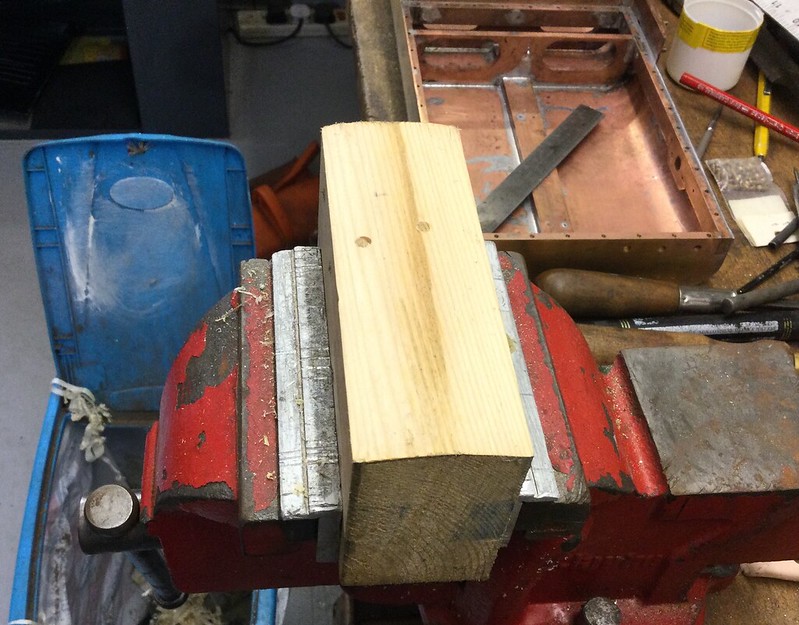 Then I milled a suitable groove in the radiused face:  To make life easier, I annealed the plate locally where the dint will go:  Then it was a simple matter of placing a suitable diameter steel bar in position and giving it a thump with a dead blow hammer:  A little bit of reshaping of the main curve was needed, but this only needed finger pressure. When screwed down, the tank back looks like this:  We seldom need to deliberately make dents in our panel work (it is more often a matter of removing them!) but this one took almost less time to do than to write about it. It is tidy enough, and the "tooling" (if I can call it that) will make it even quicker to repeat this on the other side.
|
|
|
|
Post by martyn1936 on Jan 11, 2022 17:25:52 GMT
Thanks Gary, I have found the article which adds a lot more info particularly the bit about a choke in the supply line.
Many thanks,
Martyn
|
|
|
|
Post by Roger on Jan 11, 2022 22:51:23 GMT
I'm curious to know why you chose that solution rather than just squashing the pipe at the back? There's plenty of room for the through pipe to pass the restriction.
|
|
Gary L
Elder Statesman
Posts: 1,208
|
Post by Gary L on Jan 11, 2022 23:20:46 GMT
I'm curious to know why you chose that solution rather than just squashing the pipe at the back? There's plenty of room for the through pipe to pass the restriction. Hi Roger It would be possible (just) to see the squash in the pipe from above, whereas it won't be possible to see the relief bulge in the backplate. Also, a subclause of Sod's Law says that no matter how big the pipe, you will unfailingly, always, at some stage need to pass something through it that is almost exactly too big. Finding that said object would pass the unsquashed pipe but not the squish area would be very annoying indeed! It was tempting to squash the pipe, being easier for sure, but there was also a small risk I might have broken the soldered joints in the process (rectifiable but annoying). As it turned out, I surprised myself at how quick and easy it was to create the controlled dent in the backplate! From some angles it even looks like it is meant to be there... Gary |
|
Gary L
Elder Statesman
Posts: 1,208
|
Post by Gary L on Jan 12, 2022 0:09:10 GMT
The first Pannier Tank is structurally complete!The 40/60 solder arrived today, so I was able to do the filling as mentioned before. Here is the tank back in the hearth, with the stick of solder that I will use. The stick turned out to be much thicker than expected, so I had over-ordered significantly; I daresay the unused stick will come in handy one day. Better than running out in the middle of the job! I had previously added some of this solder to the internal corners as I mentioned earlier (not shown). It proved ideal, because it doesn't run away through the gaps like common solder does, but builds up nice fillets.  You might be able to see one of the temporary aluminium dams that I clamped in place at each end of the central seam- don't want the liquid solder to run away and leave the gap starved. Here is the solder successfully applied to the groove and the hollows. My medium burner was more than adequate for the local heating needed. The 40/60 solder (AKA Body Solder) was much easier to work than normal solder, (which confusingly is called 60/40; the first number always indicates the tin content). I was quite surprised at how very different it is to use. As mentioned above, common solder melts and runs, and solidifies quickly. Body solder has a wide range between melting and solidifying, which allows you to build it up in heaps:  Next time it will be a bit neater, but this is fine for a first attempt. You have to build it significantly proud of the area that is being filled, because it contracts a lot on cooling, so you err on the safe side. You are then left with fat hummocks that need to pared back. The best tool would be a body file, which has rows of parallel, very coarse chisel-like teeth that can't clog, but I don't have one. Instead I used a carpentry chisel and mallet to rough cut the hummocks, and finished off with a coarse file followed by a sanding block and aluminium oxide paper:  There are a few very shallow blemishes and screw slots, but as I said before, knifing filler is made to deal with those. In some lights it is possible to see a slight ripple where the two intermediate bulkheads lie. I am not at all bothered by this as I was expecting it, and I had adapted the Adams bulkhead layout to make sure they were in the right place. On (very rare!) photos of clean & shiny 15xx locos, it is easy to see the ripples marking the welded bulkheads which divide the tanks into three equal lengths.
|
|
Gary L
Elder Statesman
Posts: 1,208
|
Post by Gary L on Jan 15, 2022 0:31:29 GMT
I've soldered up the second (RH) pannier tank. No photos, there is nothing to see, it looks just as grubby and messy as the first one did. I did vary the method a little though; now I have an ample supply of 40/60 Body Solder, I did the structural soldering, the leak filling, and the cosmetic filling on the outside, all in one heating. It seemed to work just as well, except for the clumsy blistered fingertip from one of the turning-over operations (hot!). The cosmetic filling on the outside is every bit as lumpy as the previous effort, so there will be quite a lot of cutting back when everything has cooled down. When using body solder to fill large areas on -er- car bodies, it is usual to use a wood tool to smooth out the solder in its semi-molten state. This reduces waste and time in removing the excess. This isn't really practical for filling the long narrow seam on the pannier tanks though, where because of its depth, it needs a decent mound building up to avoid the material contracting back into the gap (IYSWIM). But that is for tomorrow, and nobody will know or care about the lumpiness once it is all trimmed back. While the tank was cooling off, I offered up the first tank to check the mountings were still in the right place. They were! (No great mystery, they were marked and checked on the framework before the skins were attached, but nice to confirm it all still fits together!):  This view shows where the fascia plates will fit, to fill the big gap between boiler and tanks at the front: 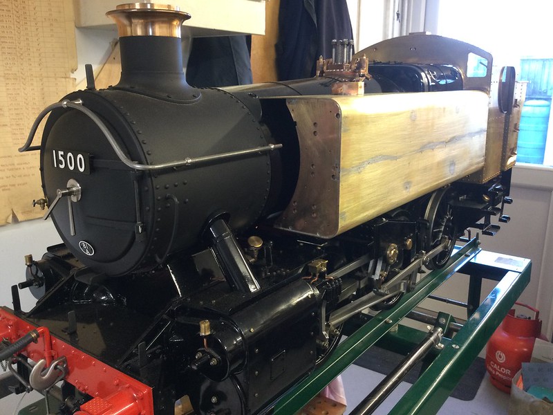 And this view shows that the tank fits tidily under the fairing angle attached to the cab front:  This did though, cause a complication with the tank fastenings. I had intended to use stainless studs fixed to the tank, and nut them up from below. But having those fairing angles already soldered to the cab (and there is no other sensible way) meant that the tank could not be lowered truly vertically to fit the studs into the holes prepared for them on the mounting brackets; thus they wouldn't engage. So that plan had to be abandoned, in favour of inserting hex screws up from below with the tank settled into position. This in turn made it necessary to solder blind nuts in a couple of places inside the tank to take the screws where they strike through unsupported skin (I had intended to use hex screws fitted from inside the tank, but this became impossible). Yes, this could have been avoided by attaching the cab after the tanks, but that would make it impossible to remove the tanks without taking the cab off first. Experience says that is not a clever feature to build in! Another unwelcome discovery was that the studs for fastening the balance pipe flanges beneath the tank, were a little too long to allow the balance pipe to be manoeuvred into place with the tank bolted down. They will have to be shortened by a few mm, even if it means that the nuts sit a little proud of the studs. It's another case where maintenance has to take precedence over appearance. It is a fairly inconspicuous place, and there is no load on the threads, so it will be OK.
|
|
|
|
Post by Roger on Jan 15, 2022 11:48:24 GMT
That looks superb! Will you be adding the steps and handrails too?
|
|
|
|
Post by fubar123 on Jan 15, 2022 17:53:09 GMT
Thing of Beauty Gary, Looks Great ! Well Done
|
|


