|
|
Post by andyhigham on Oct 12, 2020 6:46:09 GMT
Gary, I guess you listen to "Sorry I haven't a clue"
|
|
|
|
Post by Roger on Oct 12, 2020 7:50:48 GMT
Hi Gary,
There's nothing to stop you using as shallow a Vee groove as you need to get the desired bend. It would guarantee it's in the right place. A quick experiment on a piece of scrap would soon let you figure out what the depth needs to be.
|
|
Gary L
Elder Statesman

Posts: 1,208
|
Post by Gary L on Oct 12, 2020 9:31:13 GMT
Hi Gary, There's nothing to stop you using as shallow a Vee groove as you need to get the desired bend. It would guarantee it's in the right place. A quick experiment on a piece of scrap would soon let you figure out what the depth needs to be. Good point Roger. It would also ease the load on the bender, which isn’t really specified for 1.5mm. Wish I’d thought of that before I started! The groove would have helped define the edge of the big curve too, but I would have had to cut it before the annealing to have a chance of holding the plate flat enough. Note to self (and others) if I have to do this again! Gary |
|
barlowworks
Statesman
 Now finished my other projects, Britannia here I come
Posts: 874 
|
Post by barlowworks on Oct 12, 2020 14:43:59 GMT
Hi Gary, I think a groove at the start of the big curve might make a slight fold line at the start of the curve, not really what you want. You can get the same problem wth a line of pre drilled rivet holes on a curve if you are not careful.
Mike
|
|
Gary L
Elder Statesman
Posts: 1,208
|
Post by Gary L on Oct 12, 2020 23:05:44 GMT
Hi Gary, I think a groove at the start of the big curve might make a slight fold line at the start of the curve, not really what you want. You can get the same problem wth a line of pre drilled rivet holes on a curve if you are not careful. Mike Thanks for the warning Mike. As so often, I would do things differently in retrospect. I was worried about getting the large curve placed accurately, so didn't want to commit to the fold line from the beginning. If I had more confidence about that, I might have done the groove first and it might not have mattered. But it's done now, as you will see shortly... Gary |
|
Gary L
Elder Statesman
Posts: 1,208
|
Post by Gary L on Oct 13, 2020 0:24:19 GMT
Next job is the reverse fold. This should be ⅛” radius on the inside, 3/16” radius on the outside. The fold on the template rib was a normal sharp(ish) fold, so I reckon if I interpose a 1/16” strip between the folder blade and the plate, I might get close to these dimensions, if the machine will take it. Strictly speaking this material is too thick for it, but the brass has been annealed, so I might get away with it…  (Above) So far so good. Nearly there now, and pausing to check the fold is in exactly the right place. It is very slightly too low by about 1/32”, but a slight repositioning of the plate under the finger should take care of that. Now we are back in slowly-slowly mode; ‘cos i really don’t want to overbend it... (Below) This is the set-up, with the pre-folded aluminium strip fattening up the fold line a little to avoid it being too sharp. It might be visually a smidge too much the other way, comparing the prototype photo, but this is the fold radius per Adams, and as I drew it on the laser-cutting CAD file, so I have to stick to it or the bend allowance will be wrong, and that will affect the rivet hole placements. 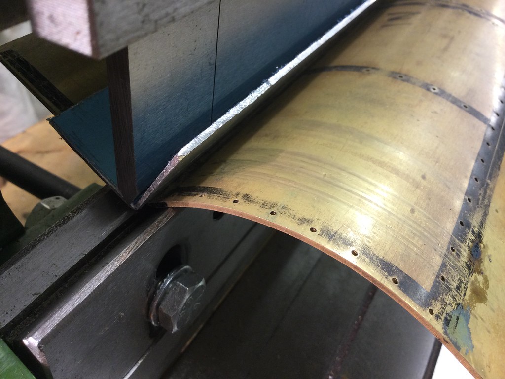
Several very gentle fold increments later, and this is the result:  Not as bad as I feared. The top of the template rib is a few thou below the edge of the plate, but it could have been worse. The folding operation has flattened the big curve slightly just below the fold line, but I doubt if it will be noticeable. The plate isn't sitting on the template in the LHS of the photo, but that is waste and will be cut away presently. There comes a point where you have to decide whether further working will make matters worse, and I think this is that point! Cosmetically, it is not as tidy as I'd hoped. You can see the tramlines from the roller grooves and I’ve collected another one or two, horizontal this time from the edge of the Vee-groove on the folder, giving an interesting tartan effect. I'm confident they can be obliterated with filler before painting, so I'm not too worried about it, it's just another job to do. If I use lead to fill all the tramlines it will add some useful ballast  Actually, the need for filler will affect the decision about how to fix the bunker top edge trim in place. To get a decent result in amongst the rivet heads, the filling needs to be done before the rivets are set. If I use lead, and then try to solder the edge trim in place it might not go well, even though pure lead has a somewhat higher MP than most soft solders. Epoxy filler doesn't like heat either, though I have some " JB Weld" which is alleged to stand " intermittent heat up to 500 degrees F" -which sounds impressive until you translate it into 260 degrees C, which is back in soldering temperature territory. JBW is also full of fillers, so it is very thick and not very sticky, so not an ideal material anyway. I might have to resort to prototypical tiny rivets after all! I'll sleep on it for a week or two. Very happy there is no more serious folding to do! (Or is there?)... |
|
|
|
Post by David on Oct 13, 2020 4:05:25 GMT
For someone who seems to hate sheet metal work as much as I do, you're getting excellent results! The bottom back of bunker went really well and it looks like you got as good a result as can be reasonably expected with the top so far. I can't see anything wrong with it at all.
|
|
barlowworks
Statesman
Now finished my other projects, Britannia here I come
Posts: 874
|
Post by barlowworks on Oct 13, 2020 4:54:26 GMT
Hi Gary, the reason I know this isn't through 5 inch platewotk but a lifetime modelling in O gauge. It is a favourite trick of etched kit designers to put lines of half etched detail on curves and awkward places making it impossible to get a smooth finish or edge. I just assume that it would cause a similar problem in the larger scale. Better to have an idea there might be a problem than to find out after when it's too late. The bunker is looking brilliant by the way.
Mike
|
|
|
|
Post by Roger on Oct 13, 2020 7:05:13 GMT
That's a good result on something that tricky. Leaving a little metal on the edges to trim away when it's been folded can make life a lot easier. You still need to get the bends close to the right positions, but you can make small corrections.
Are you going to try to simulate the joint between the two plates that this is normally made from?
|
|
Gary L
Elder Statesman
Posts: 1,208
|
Post by Gary L on Oct 13, 2020 14:32:07 GMT
For someone who seems to hate sheet metal work as much as I do, you're getting excellent results! The bottom back of bunker went really well and it looks like you got as good a result as can be reasonably expected with the top so far. I can't see anything wrong with it at all. Thanks David, that’s very kind, but it is very early days, and still a bit of a fluke I think. Plenty of opportunities yet to make a mess! Gary |
|
Gary L
Elder Statesman
Posts: 1,208
|
Post by Gary L on Oct 13, 2020 14:59:25 GMT
That's a good result on something that tricky. Leaving a little metal on the edges to trim away when it's been folded can make life a lot easier. You still need to get the bends close to the right positions, but you can make small corrections. Are you going to try to simulate the joint between the two plates that this is normally made from? Ah no Roger, indeed not! I’m modelling 1500 in the early years, and in those days the bunkers were made with a single long plate at the rear. It must have been very unwieldy, so it is not surprising that for the SVR rebuild of 1501 they did it in two parts, divided at the C/L. Perhaps it was a matter of availability too... a single plate of that length would almost need a lorry to itself, and be very vulnerable to damage in transit. I expect Swindon kept stacks of the stuff and it was never a problem. We’ll see how accurate the plate is when I marry it to the lower plate. It was a bit if a gamble to have the rivet holes cut before bending, but if it comes off it will be a major saving in time and error. As you have pointed out, the rivet spacings are all over the place on this job, no doubt for good reasons, but it means that what is ‘right’ often looks ‘wrong’ and v/v, so working it all out in the workshop on the metal had no appeal at all. There are two bend allowances that need to be spot on for the lower row of rivets on this plate to fall in the correct place, which was always going to be chancy. I reckon an error of say 1/16” either way will be acceptable, more than that and I will have a lot more filling and drilling to do! Gary |
|
Gary L
Elder Statesman
Posts: 1,208
|
Post by Gary L on Oct 13, 2020 15:13:05 GMT
Hi Gary, the reason I know this isn't through 5 inch platewotk but a lifetime modelling in O gauge. It is a favourite trick of etched kit designers to put lines of half etched detail on curves and awkward places making it impossible to get a smooth finish or edge. I just assume that it would cause a similar problem in the larger scale. Better to have an idea there might be a problem than to find out after when it's too late. The bunker is looking brilliant by the way. Mike Thanks again Mike. I too dabbled in Gauge O before getting interested in the big stuff, and having seen the accuracy and finish of an etched kit I had no further interest in doing plates the old-fashioned way. I don’t see anything disreputable in contracting out sections of the project to a 3rd party. I was a bit chary of getting the rivet positions cut before bending, for exactly the reason you mention, but if it came off the benefits would be huge. I felt that since the holes were relatively small, and if I annealed the metal before bending to minimise any spring, it should work out OK. It is early days, but the first plate was encouraging. The roof will be an adventure! Gary |
|
|
|
Post by Deleted on Oct 13, 2020 15:19:03 GMT
Nice work Gary, never easy trying to line something up on the formit as most things you are doing 'half-blind' if you get what I mean?
Great work
Pete
|
|
Gary L
Elder Statesman
Posts: 1,208
|
Post by Gary L on Oct 13, 2020 17:22:17 GMT
Nice work Gary, never easy trying to line something up on the formit as most things you are doing 'half-blind' if you get what I mean? Great work Pete Very much so Pete! When the workpiece gets close to the arms at each side it is very tricky. I couldn’t even get a dentist’s mirror in to get a direct line of sight at the RHS! So under the circumstances getting within a few thou of the required position represents considerable luck as much as anything! We often don’t think of such matters when buying our machines. But in the case of the Formit I didn’t have room for a bigger model, and I think the smaller version is likely to be stronger. This is the first time I have used it so close to its limits, though as you can see, I haven’t had much practice with it at all. Gary |
|
|
|
Post by coniston on Oct 13, 2020 21:44:00 GMT
Very neat work Gary, I'd be more than pleased with that result. Not sure if you will need filler if you can remove most of the marks with emery / wet & dry then use a filler primer (2 pack etch type0 as used in the automotive trade, a couple of coats of that well sanded with fine wet & dry used wet with soap to prevent clogging should be all you need.
Chris D
|
|
Gary L
Elder Statesman
Posts: 1,208
|
Post by Gary L on Oct 13, 2020 23:59:45 GMT
Very neat work Gary, I'd be more than pleased with that result. Not sure if you will need filler if you can remove most of the marks with emery / wet & dry then use a filler primer (2 pack etch type0 as used in the automotive trade, a couple of coats of that well sanded with fine wet & dry used wet with soap to prevent clogging should be all you need. Chris D Very kind of you to say so Chris, but I think the grooves along the fold are too deep to cover with primer-filler. I might get away with it on the scores from the roller though, so I'll probably do those last, even though it might mean some intricate rubbing down round a few rivets. Having thought about it, I might lead-fill the deep grooves near the fold early on. If I use soft solder for the top edge trim, which is my preferred way, I think if I'm careful the heat will have too far to travel to upset it. If it does... too bad, it'll be back to the body filler. -Gary |
|
Gary L
Elder Statesman
Posts: 1,208
|
Post by Gary L on Oct 16, 2020 0:48:46 GMT
Drilling the laser-cut rivet holes through to the butt straps at each end of the upper bunker plate. It is not possible to do this before bending because of the alignment issues this would cause. A similar operation has been done the same way on the three ribs made earlier. I was expecting this to be tricky, because of the curvature of the plate... 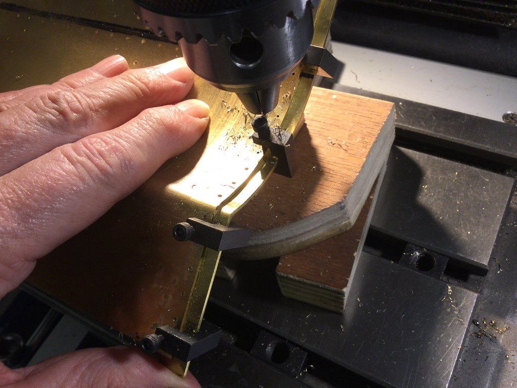 This freehand drilling doesn't look very accurate or even very steady, but it works surprisingly well. The fine drill is not a safety hazard; it can't snatch a component this size. What's more, the apparent wobbliness is the chief virtue of the method. To clamp the plate down, or to mount it in a vice, brings almost insoluble issues of how to drill perpendicular to the curved face. Doing it this way though, with a very light touch, the pressure of the drill causes the plate to roll automatically until exactly the right angle is reached. Make sure the plate is realigned so the drill bit is central to each hole of course, and away you go. There is a method of levelling a lathe tool by pressing it on a rule held against the circumference of a true-running workpiece until the rule is held vertical, and this method uses a similar principle. Did I mention the very light touch? The sharp-eyed amongst us will notice that one of the mini-clamps is too close to a hole, so the clamp will need to be moved to finish the row. |
|
Gary L
Elder Statesman
Posts: 1,208
|
Post by Gary L on Oct 18, 2020 0:18:17 GMT
A very careful dimensional check against the Cab Sides (which incorporate about half the bunker's length) shows that once again the bend allowance has worked out just right; possibly a little over by 20 thou or so. I must stop sounding so surprised, but in the past (with less important jobs and no calculations) it was always in the lap of the gods, and they were usually unkind. Anyway, I can safely cut off the inch or so waste strip and clean up the edge. No photos of this; a bandsaw would be the ideal tool, but lacking that, I resort to the trusty jigsaw (with metal-cutting blade of course). Not the perfect tool, but it works for cuts like this where a hacksaw hasn't a hope because of the length of the cut. The truing up afterwards wasn't my finest moment, but paint will hide the imperfections. The cut line needs to take off a small amount more than an exact match with the other plate; partly to compensate for the aforesaid 20 thou oversize, and another thou or two so the join won't be totally hidden by the paint. If I'd been clever, I could have bevelled the plate edges a little to achieve that effect, but I'll remember that for the remaining seams, which are more exposed than this one. The join between the plates needs to be considerably more than 'scale'. A scale gap would be practically unmeasurable, and hard to keep constant. Thus the plates would inevitably touch in some places, and thus disappear under the paint, and not in others where it would gape, and the net effect would be nasty. Make the gap a touch wider, and the eye won't see the irregularities. It is why in carpentry 'Tongue & grooved' joints are always edged with a big bevel, so the eye doesn't notice variations in the gap between planks. Anyway, with that done, it's possible to cut, bend and drill the butt strap that joins this plate to the lower bunker plate. It's in two parts, to save worrying about the positioning of the bends at the outer ends, which have to match the lower plate. Bend first, using a piece of steel rod to get the radius right (it has to be 1/16" less than the lower plate to allow for the thickness of the strap, so the jig I made for that plate is no further use) then measure the length to the edges of the central rib and cut and square off accurately. The short leg is left over-length for now. Clamp in position on the lower plate, through-drill all rivet holes, then it can be temporarily fixed in place with 12BA nuts and bolts so the same operation can be done on the mating edge of the upper plate...  A mini-clamp at each end is sufficient. This time the assembly is firmly clamped on the mill table, lined up with the wiggler and full advantage taken of the dividing function on the DRO. It is important to line the rivets up so both rows are parallel and lined up vertically as well. These were pre-cut by the laser, so they are dead-on accurate, whereas the trimmed edge of the upper plate might not be. Once again there isn't great support under the drill, so gently-gently is the rule... Lots of holes later, and it is possible to temporarily bolt both plates together, and then insert and temporaily bolt the middle rib (the top half is already drilled of course), clamping it dead square at the bottom for another drilling session tomorrow...  It has the great advantage of stiffening the assembly considerably, and relieving the strain on the tiny bolts. Rivetting them together permanently is still a long way off, I think. I think my photos are displaying inconveniently large on screen. I'll go down a size or two for the next instalments. |
|
|
|
Post by coniston on Oct 18, 2020 19:34:14 GMT
That's coming on nicely Gary, and your photos are just fine for me, nice and clear.
Chris D
|
|
|
|
Post by andyhigham on Oct 18, 2020 20:29:03 GMT
I'm waiting on tenterhooks for the 3 dimensional curves
|
|


