jma1009
Elder Statesman

Posts: 5,901
|
Post by jma1009 on Jan 15, 2022 21:15:35 GMT
Hi Gary,
That looks very good and well done!
Martyn, at the risk of hijacking Gary's thread for the hydrostatic lubricator sight glasses you need a nozzle at the base of the sight glass drilled 0.45mm or 0.5mm. 1mm is far too big, but will suffice for the choke needed at the end of the delivery pipe from sight glass to steam pipe(s)/steam chest(s). 1mm for nozzles is greater than the 1/32" Cottam/Evans design that I have been critical of.
Cheers, Julian
|
|
Gary L
Elder Statesman
Posts: 1,208
|
Post by Gary L on Jan 15, 2022 23:50:34 GMT
Hi Gary, That looks very good and well done! Martyn, at the risk of hijacking Gary's thread for the hydrostatic lubricator sight glasses you need a nozzle at the base of the sight glass drilled 0.45mm or 0.5mm. 1mm is far too big, but will suffice for the choke needed at the end of the delivery pipe from sight glass to steam pipe(s)/steam chest(s). 1mm for nozzles is greater than the 1/32" Cottam/Evans design that I have been critical of. Cheers, Julian No problem at all. Good to see you back Julian, and thanks! We've missed you. Thanks to Roger and Fubar123 too for the kind words. Roger; the steps and a handrail fit onto the fascia plate that fills the gap. I think I will silver-solder the steps on; I haven't decided about the handrail. The fascia plate is fixed to the tank with an array of flush csk screws; I think I will back it with epoxy. That will allow me to fill the joint and the screw slots, but it will be possible to remove them later if the need arises, to repair damage for example. (Epoxy can be softened with a hot air gun without affecting the soft-soldered tanks and maybe without damaging the paint too much) Now both tanks are soldered up, it is all about finish and detail from now on... Gary |
|
|
|
Post by Roger on Jan 16, 2022 11:58:49 GMT
Hi Gary, That looks very good and well done! Martyn, at the risk of hijacking Gary's thread for the hydrostatic lubricator sight glasses you need a nozzle at the base of the sight glass drilled 0.45mm or 0.5mm. 1mm is far too big, but will suffice for the choke needed at the end of the delivery pipe from sight glass to steam pipe(s)/steam chest(s). 1mm for nozzles is greater than the 1/32" Cottam/Evans design that I have been critical of. Cheers, Julian No problem at all. Good to see you back Julian, and thanks! We've missed you. Thanks to Roger and Fubar123 too for the kind words. Roger; the steps and a handrail fit onto the fascia plate that fills the gap. I think I will silver-solder the steps on; I haven't decided about the handrail. The fascia plate is fixed to the tank with an array of flush csk screws; I think I will back it with epoxy. That will allow me to fill the joint and the screw slots, but it will be possible to remove them later if the need arises, to repair damage for example. (Epoxy can be softened with a hot air gun without affecting the soft-soldered tanks and maybe without damaging the paint too much) Now both tanks are soldered up, it is all about finish and detail from now on... Gary Ah, I see. I guess there's no easy way to fit all of the detail if the Tank front doesn't go all the way to the Boiler. There's also another hand rail on the top of the Tanks at the front which might be tricky to attach, since only one end is on the tank, the other is in the gap. |
|
|
|
Post by martyn1936 on Jan 16, 2022 23:15:06 GMT
Hi Roger, Thank you for the information on the jet size, I will continue the discussion in my thread on the Hawksworth loco to stop interrupting this thread but Gary's raises so many questions for me and is so helpful as he is a year ahead of me.
Thank you both,
Martyn
|
|
Gary L
Elder Statesman
Posts: 1,208
|
Post by Gary L on Jan 17, 2022 12:04:48 GMT
No problem at all. Good to see you back Julian, and thanks! We've missed you. Thanks to Roger and Fubar123 too for the kind words. Roger; the steps and a handrail fit onto the fascia plate that fills the gap. I think I will silver-solder the steps on; I haven't decided about the handrail. The fascia plate is fixed to the tank with an array of flush csk screws; I think I will back it with epoxy. That will allow me to fill the joint and the screw slots, but it will be possible to remove them later if the need arises, to repair damage for example. (Epoxy can be softened with a hot air gun without affecting the soft-soldered tanks and maybe without damaging the paint too much) Now both tanks are soldered up, it is all about finish and detail from now on... Gary Ah, I see. I guess there's no easy way to fit all of the detail if the Tank front doesn't go all the way to the Boiler. There's also another hand rail on the top of the Tanks at the front which might be tricky to attach, since only one end is on the tank, the other is in the gap. Roger: The handrail end ’in the gap’ is dead easy, the gap is in front, not on top. The end in the tank is less so, because being BMS* it needs to be waterproofed. Blind nuts are obviously not possible. I shall probably have to encase it, and the nut, in a big blob of epoxy, or possibly polyurethane sealant. This is the handrail ‘on top’ of course. The handrail on the front face is fixed to the fascia plate. *I’m not a fan of stainless handrails. A bit too much like Detroit chrome for my liking, and in many places (not all) Swindon painted their handrails, rather than leaving them bright. But I admit I am inconsistent. Martyn: Did you mean Julian?? Gary |
|
|
|
Post by martyn1936 on Jan 17, 2022 14:16:52 GMT
Sorry, yes I meant Julian. I somehow expected it to be Roger who wrote the message as he has been very helpful to me. Not thinking first, so apologies Julian.
Martyn
|
|
Gary L
Elder Statesman
Posts: 1,208
|
Post by Gary L on Jan 19, 2022 0:09:52 GMT
Both the Pannier Tanks are now temporarily installed so that the remaining details and components can be fitted. First up are the Cross-Tie Girders. On the real thing these are made from 6" x 3" x ½" rolled Tee section, but the chances of finding a corresponding scale section are vanishingly small, even if the heavy rolling involved was feasible. So these will be fabricated from 16g steel (which usually turns out to be 15g, as here). I already had some laser-cut profiles, but with all the variables involved with boiler cleading, these were mostly drawn by optimistic guesswork. Anyway, balancing the profiles on the already-made support chocks gives me an idea of how close the guesswork was...  On the full-size, the tie girders are fitted very close to the cleading; a 1/16" gap is specified on the works drawings, but scaling this is obviously impractical, if only because our copper boilers expand more pro-rata than the full-size steel ones do. But the model ties need to be visually close to the boiler to be satisfying, without risk of damaging the paintwork as things move and breathe; I'll be happy with something in the order of 1/32"-1/16". Bearing in mind that the base web has to be attached, you can just about see that the front tie is pretty good, but the rear tie is going to need some adjustment. I started with the front tie therefore, because that would be the easy one. Here are the bits:  It just needed som judicious shaping of the bottom web, then the parts could be clamped and silver-soldered together:  I used Roger's trick of covering all the steel surface in flux, though I am a bit stingy, and I only applied the thinnest smear of flux paste, except where the join was to be. Then the usual method of pre-applying thin solder wire either side of the joint; the photo shows the job after the heating. I checked the squareness and centrality of the vertical web first, obviously, and in 15g material it isn't hard to maintain the squareness when clamped. There is no black scale on the steel- the black areas in the photo are Tenacity flux that has cooled to glass-like blobs. (But to be fair, I didn't flux the underside of the assembly, and that didn't have any black scale either!) A quench and a bit of emery soon had the item polished up, then the ends of the bottom web were trimmed back square in the mill:  Reflections make the solder appear blobby in places, but it is just a trick of the light. I'm very happy with that; the clearance over the boiler is just right. From the front it looks quite generous, but at the back there is only about 10 thou minimum clearance, because of the boiler taper. The Rear Tie is going to be more difficult. It can't be scaled, because the Adams firebox is significantly bigger and taller than it should be:  From the close-up above, you can see that my educated guesswork wasn't so good; there is too much clearance over the firebox crown, and not enough at the sides. (At the other side this embryo tie is touching the cleading, so the visible gap at the side here is all that is available, but it needs to accommodate two thicknesses of bottom web, plus a working clearance). I have a PLAN, but that is for tomorrow... |
|
|
|
Post by doubletop on Jan 20, 2022 20:20:24 GMT
Checking Gary’s thread has become a daily routine for me. He is so far ahead of me he is always tackling something that I am going to have to do later on my Dart Platework thread. Although Gary had drawn up his own platework design and had MEL to cut it for him and my platework was drawn by John Smith and produced by Polly Model there are striking similarities. But that is GWR for you. I asked Gary the other day if he had any drawings for the cab seats and he pointed me back to the relevant part of his thread, not only the drawings but the “how-to”. Although my thread will not have a lot more to offer I guess if you are doing a 7.25” GWR tank loco it would pay to refer to both threads. Pete |
|
Gary L
Elder Statesman
Posts: 1,208
|
Post by Gary L on Jan 23, 2022 17:45:40 GMT
The Rear Cross-Tie Girder is similar in construction to the Front one, but more elaborate and certainly more awkward to get right, because it needs to follow the profile of the firebox crown cleading, which is unlikely to conform exactly to anybody's drawings. There are just too many variables, even assuming the boiler itself is built accurately. (I don't mean to offend any professional boiler makers who are misguided enough to be reading this thread, but I'm pretty sure they don't generally work to tolerances in thous, and even if they did, it would be hard for the averagely skilful model engineer to clothe one of their products to that kind of accuracy! And anybody who can build a boiler to micrometer exactness is unlike to be reading this thread, except for a good laugh!) Anyway, I had two attempts at drawing a laser-cut spine for this girder, and neither of them came very close to the actual profile of the firebox:  But nothing lost. The shape is a long and difficult one to cut with hand tools, and rather than start again for a third try at a laser-cut, I decided to adapt the better of the two I already had:  Step 1 as in the photo above, was to cut off the lower limb of the laser-cut shape on each side, and replace them with trapezoids of the same thickness. Care was taken to make sure the cuts were at the identical height, and that the trapezoids were identical mirror-images, and of a height to bring the overall height of the structure to exactly the clearance over the firebox that I wanted. This was not particularly difficult to determine, because the thickness of the bottom web does not need to be allowed for, because it is the same all round (obvs); you just need to add the desired clearance to the height. In the photo above, the bits are assembled ready for silver-soldering the trapezoids to what is left of the top arch. The cut-off bits are shown purely for interest's sake. The bar along the bottom is not to be silver soldered! It is there to keep everything in line and in place. (It happens to be the future bottom web of the girder, but any straight bit of steel would do.) The silver-solder is a medium-melting point, to be sure it won't fall apart in the last step. Having successfully joined the three bits together, the joints were linished flat, and then the internal profile marked and cut out:  There are various methods of marking the profile, but it is necessary to remember that the thickness of the lower web has to be allowed for all round this time. (I imagine that a profile gauge would be the ideal way of doing it. My way was to use the other, redundant and least-well fitting spine profile as a frame, and stick Blu-Tak inside it to get the shape.) Cut out to your line with a piercing saw, clean up with a file. Then, once the internal profile is satisfactory, cut the outside profile in the same way. (I was able to use one of the original cut-off bits as a template, YMMV): 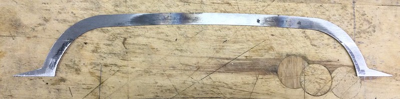 I'll draw a polite veil over the shaping of the bottom web to fit inside the new spine profile, which you can see in the photo below. Take it slowly, It needs care (and a certain amount of luck!) It needs to fit very snugly, but it doesn't matter if it has to be sprung into position, as you will see. The Formit should have been the ideal tool for the bends, but I didn't find it so. The material is only 15g steel, and can almost be shaped by hand. (n fact, I found a metal disc of roughly the right diameter, fixed it in a vice, and pressed the strip around it, then did the final shaping freehand). The Formit was however useful for making the two folds at the lower inner corners. In passing, I should have said that I didn't find anybody willing to supply ¾" x 1/16" BMS, so I hacksawed it from sheet and milled the edges to get them straight and parallel. None of the steel is the leaded sort, which is reputed to be undesirable for silver soldering, (though I haven't personally had any issues with it). So it is then just necessary to flux the two parts in the usual way, and clamp them together for soldering. (A bit of 'spring' in the bottom web is actually helpful in keeping everything in intimate contact.) Put a clamp wherever there is a gape in the joint. Check that the 'spine' is central and square throughout. Lay the lengths of lowest-temp silver-solder wire into the flux each side of the join, and bake to a golden brown...  ..Or indeed black. But note that the heating needs to start in the middle of the girder. Once that part is securely stuck together, move outwards with the torch and do first one side, then the other. This prevents any difficulty from differential expansion, as the vertical rib will tend to get hotter than the bottom web. Also the clamps must be heated up first, or they will soak up the heat and stop the solder melting locally. (I was surprised at how much heat this job took, and I had to swap burners for my biggest one half-way through.) Finally after trimming and cleaning, here is the finished product. A bit of paint will cover any imperfections!  The next job will be to accurately transfer the holes for the mounting bolts to both Cross Ties (front and back) and to the tanks themselves. |
|
Gary L
Elder Statesman
Posts: 1,208
|
Post by Gary L on Jan 24, 2022 20:17:47 GMT
Pannier Tank Cross-Tie Girders (continued) It just remains to drill the mounting holes (1) in the Cross Tie itself, then (2) into the tanks. The support blocks were made quite a while back. I followed the Adams intention, whereby the Support Blocks are bolted to the tanks, though in the prototype they are welded on. It is a pity to have to deviate visibly in this way, though I'm not sure there is a satisfactory alternative. Silver-soldering is out of the question at this stage, and I'm not sure that soft-solder would be reliable. (There shouldn't be much load in the ordinary way, but the tanks are a natural place to grab or push a loco, and this could cause some unfair strains.) Anyway, bolts (or studs) it will be... First I used solder paint to temporarily attach the Support Blocks to the Cross-Ties with the correct 1/16" underhang. Here is the front one being readied for soldering:  The two bars are to keep the Blocks in alignment, while the calliper gauge is used to set the 1/16" underhang from the girder on top. (To be clearer, the Blocks protrude by 1/16" from each end of the Girder). Check the girder is aligned laterally; the two aligning bars can then be removed. Weight holds everything in place while the heat is applied with a torch to sweat the solder, as here with the Rear Girder:  Then to the mill for drilling, upside down supported in the vice with parallels. The DRO is a double-check on accuracy, squareness and centrality of the array of holes:  Then the assemblies can be used as templates to spot-through for the holes in the tanks themselves; here is the front one. Once the dimensional location was carefully scribed onto the tank I used Super Glue to secure the assembly temporarily in place. (It holds so well, I'm wondering now if solder was the best choice for the tie-to-block joint. But it doesn't matter.)  As you can see from the felt-pen notes, one of the holes at each block will need special treatment, because it conflicts with a tapped hole in the underlying framework for one of the tank inner access plate screws. I used a Dremel-type tool to spot through; these do not have much mass so there is not much danger of damaging the existing holes. And here is one of the rear ties. It was only necessary here to align the tie fore-and-aft. Equal clearances were needed athwartships at the firebox, this was done by building up layers of masking tape to remove any slop. The solder stain that is visible on the block is not a careless accident BTW, (though I get plenty of those too!) I deliberately put a spot of solder paint in a visible place, so that I can judge when the right heat has been attained. It will easily scrape off later.  The last step will be drill and tap through from the spotted holes using the mill, next time the tanks are removed, which could be a while away. This is so self-explanatory that I won't say any more about it in this blog. (If I was only drilling through the skin, I might have been tempted to drill all the way through in-situ with a hand drill, but many of the holes will pass all the way through the ¼" brass tank frames, and that would have been tempting fate too much. ---------------------- Completely unconnected with this, because it concerns my build before the platework was started, but here is a cross-reference to a discussion about the choice of Snifting Valves for Paddington. (David Adams's drawings offer a choice between two types.)
|
|
|
|
Post by martyn1936 on Feb 1, 2022 17:42:33 GMT
Hi Gary, When you made your safety valves did you build them to the Adam's design? I am unfamiliar with this style of valve but one of the 5" GWR tanks at club has a support for the spindle lower down not just the bar at the top. I am machining the casting at the moment and just want to be sure I am following the right path. Apologies for asking silly questions.
Martyn
|
|
Gary L
Elder Statesman
Posts: 1,208
|
Post by Gary L on Feb 2, 2022 0:36:11 GMT
Hi Gary, When you made your safety valves did you build them to the Adam's design? I am unfamiliar with this style of valve but one of the 5" GWR tanks at club has a support for the spindle lower down not just the bar at the top. I am machining the casting at the moment and just want to be sure I am following the right path. Apologies for asking silly questions. Martyn Hi Martyn Not very, but since I already had the boiler I had to base mine on the same mounting and castings. There are several features of the Adams valve that I don't care for, not the least of which is that the spring retainers are the wrong shape. This is purely cosmetic, but very obvious from above, which is where our locos are viewed from. There should also be a rim around the base casting; I added this by silver-soldering on some brass strip. It affects the functioning of a GWR-type valve; there is a discussion of its function in Roger's thread. Finally, I dislike balls and any suggestion of 'pop' valves within a GWR outline; they work, but not in a GWR way. I have Gordon Smith soft pops on my Bridget, and they are very good, but wholly inappropriate for a Swindon loco. It is a characteristic that Swindon valves 'feather', and this requires a Wing Valve (a vaguely poppet-type valve but with the pressure point below the level of the seat). Before anybody says they don't work in models, they do, if made well, and I was very happy with my Speedy's valve once I had corrected it. E J Nutty's little booklet has been mentioned several times in this forum, but it his drawings are very handy for getting proportions right, even though they are not dimensioned. No doubt these remarks will be contentious, and I don't really want to 'light the blue touch paper' so my advice would be to follow the Adams leading dimensions until you feel confident enough to try your own thing. Correct the cosmetics if you can, and definitely add the base rim. Finally (top tip!) put a blind tapped hole dead centre on the base, about 3/16" dia. When the time comes for a hydraulic test, screw in a length of studding with a stout crossbar to bear on the tops of the valve stems. Tighten down on the crossbar, and you won't have to remove all those set-screws to blank off the safety valves for the test! (Tip from David Aitken's series in EiM on the Collett 2251 Goods about ten years ago) HTH Gary |
|
|
|
Post by Roger on Feb 2, 2022 8:08:57 GMT
Hi Gary, When you made your safety valves did you build them to the Adam's design? I am unfamiliar with this style of valve but one of the 5" GWR tanks at club has a support for the spindle lower down not just the bar at the top. I am machining the casting at the moment and just want to be sure I am following the right path. Apologies for asking silly questions. Martyn Hi Martyn Not very, but since I already had the boiler I had to base mine on the same mounting and castings. There are several features of the Adams valve that I don't care for, not the least of which is that the spring retainers are the wrong shape. This is purely cosmetic, but very obvious from above, which is where our locos are viewed from. There should also be a rim around the base casting; I added this by silver-soldering on some brass strip. It affects the functioning of a GWR-type valve; there is a discussion of its function in Roger's thread. Finally, I dislike balls and any suggestion of 'pop' valves within a GWR outline; they work, but not in a GWR way. I have Gordon Smith soft pops on my Bridget, and they are very good, but wholly inappropriate for a Swindon loco. It is a characteristic that Swindon valves 'feather', and this requires a Wing Valve (a vaguely poppet-type valve but with the pressure point below the level of the seat). Before anybody says they don't work in models, they do, if made well, and I was very happy with my Speedy's valve once I had corrected it. E J Nutty's little booklet has been mentioned several times in this forum, but it his drawings are very handy for getting proportions right, even though they are not dimensioned. No doubt these remarks will be contentious, and I don't really want to 'light the blue touch paper' so my advice would be to follow the Adams leading dimensions until you feel confident enough to try your own thing. Correct the cosmetics if you can, and definitely add the base rim. Finally (top tip!) put a blind tapped hole dead centre on the base, about 3/16" dia. When the time comes for a hydraulic test, screw in a length of studding with a stout crossbar to bear on the tops of the valve stems. Tighten down on the crossbar, and you won't have to remove all those set-screws to blank off the safety valves for the test! (Tip from David Aitken's series in EiM on the Collett 2251 Goods about ten years ago) HTH Gary Out of interest, this is what's actually on 1501.  20140204_113624 20140204_113624 by Timothy Froud, on Flickr |
|
|
|
Post by martyn1936 on Feb 2, 2022 14:30:27 GMT
Thanks Gary. I have put in the blind hole as you suggested. I now need to find out some more info on the design you referred to before I remove the casting from the mill. So far I have only put in the holes for the ball and have not put in the 8 thou recess for the pop action. I'll leave it like that until I understand the new design. I have ordered the Polly springs that match Adam's dimensions and while I wait for those there is plenty to do on the lathe.
Much appreciated.
Martyn
|
|
Gary L
Elder Statesman
Posts: 1,208
|
Post by Gary L on Feb 2, 2022 22:42:07 GMT
Thanks Gary. I have put in the blind hole as you suggested. I now need to find out some more info on the design you referred to before I remove the casting from the mill. So far I have only put in the holes for the ball and have not put in the 8 thou recess for the pop action. I'll leave it like that until I understand the new design. I have ordered the Polly springs that match Adam's dimensions and while I wait for those there is plenty to do on the lathe. Much appreciated. Martyn Hi Martyn PM sent (check 'Messages' in this site's header menu) Gary |
|
Gary L
Elder Statesman
Posts: 1,208
|
Post by Gary L on Feb 3, 2022 1:16:45 GMT
With the main structural components virtually finished, what remains of the platework is largely cosmetic details... I'm probably not alone in preferring to make detail items, if only because they are low-stress. If something goes wrong, it isn't vitally important (or expensive) so just do it again! However it is going to seem a bit disorganised, because several parts are being worked on concurrently, due to the nature of the process and the fact that the tanks are quite fiddly to mount and dismount onto the chassis, so it isn't something I want to do too often! This is the list of jobs: 1. The cosmetic Fascia Plates. These screw to the front of the tanks, and carry three steps each and a handrail. (These are special to the Adams tank construction method) 2. The Trim Plates or Fairings that fill the gaps between tanks and boiler. (They are called 'Cover Plates' on the works drawing- not very specific! The Adams drawings do not include them at all.) 3. The Balance Pipe requires surgery so it will fit in the gap between the boiler and the mainframes. When all three jobs are done, and the necessary holes drilled and tapped in the tanks, it will be time to get the cab and tanks painted, Hooray! Tonight's entry covers the first part of Job No.2. Here is what the full-size looks like, using two of Roger's valuable photos: First from the front. The upper trim plate is mostly hidden by the lagged ejector exhaust pipe, but it gives a good view of the tank front. The front trims are straightforward arcs to draw, but making them means beating round a former to get the return angle: 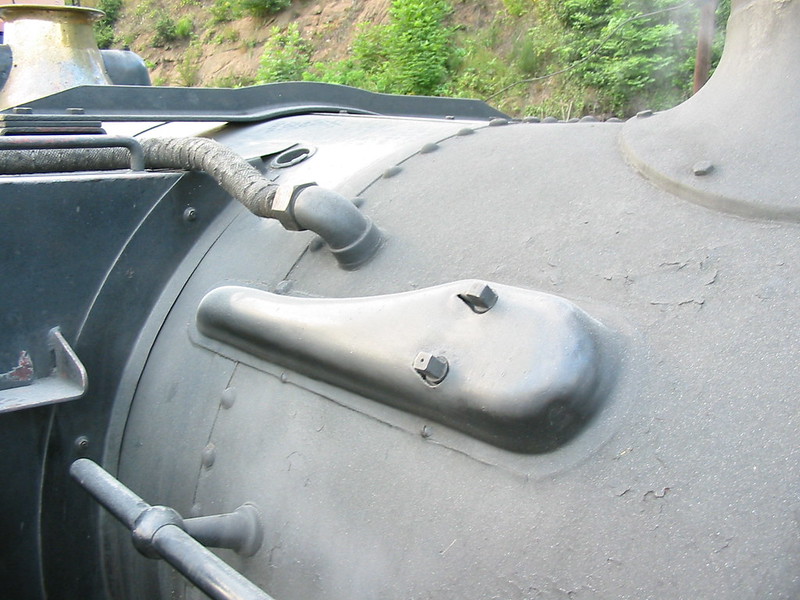 Below is where it will go on the model. The fascia plates (Job No. 1) are loosely fitted in position, but as yet lacking in furniture. You can just make out the tiny 12BA tapped holes where the screws for the trim plates go. These were spotted on the laser cut plates, and the beauty of the process is that the same positions can be used for an exact match for the embryo trim plates. I already had these, they were cut by Ed some months ago, but I realised that I had ordered them too thick, so I have ordered the same cuts exactly but in 0.5mm brass, the thinnest material available:  This excellent (and rare!) view from above shows the tank top trim, which is quite a complicated shape, so once again I'm going to get it cut by MEL:  This will also be in 0.5mm brass. Yes, I know how easy it is to cut this material with hand tools, but it is also quite difficult to keep it flat, and to get into the the intricate scalloping. Since I would have to buy the necessary brass sheet anyway, it makes perfect sense to get Ed to cut it and save a lot of trouble, and probably for very little extra net expense. ( Martyn: this photo also gives an excellent top view of (half of) the safety valve components; enough for you to see how yours ought to look?) Starting with the tank top trim, it looks quite straightforward in the photo, but in reality it is a very elongated 'S' shape, because it continues aft to wrap around the firebox as well. Plotting the exact contour is something of a 3D puzzle. It is impossible to plan it 'in the flat', it can only be done on the part-assembled model itself, involving quite a lot of trial and even more error. Paper is cheap, brass is expensive. Paper though, is opaque, and its edges are soft, so not an ideal material to make an accurate template from. However I had a light-bulb moment, and remembered a box of laser-printable drafting film I bought for a job I can't remember almost three decades ago! It's called Hydrocopy translucent, and is 100 microns thick; I've no idea if it is still available, nor where from... This film is hard but flexible, and can take pencil marks very easily. So starting from a rough outline:  Then refining the positions of the tank furniture using a digital calliper. (Important to get the cut-outs right for their own sake, but also because these in turn provide the coordinates to get the final job in the correct position.) Transfer the whole lot into CAD, and print out a draft onto the same material:  ...which can then be cut out and tried in place:  The draft shows up a couple of errors (at the firebox front), and an artifact from the printing, but these can be corrected in software and the result tried again. Quick to describe, but all this accounted for a day or two's intermittent, but quite pleasant work. It is not completely clear from any of the photos that the trim plates angle upwards by about 8 degrees to meet the boiler, from a fold line that is 3" (scaling to ⅜") from the outer edge of the trim. There is another fold line adjacent to the boiler, to bring the trim to meet the boiler tangentially. Moving aft, it butts against the front of the firebox, then at the firebox sides changes to a radiused upstand. There is no guarantee that both sides will be symmetrical, though (by chance) mine are, within about 1/16" maximum error, and I can lose that. The translucent film allows a check that the scaled fixing bolt positions do not conflict with existing fastenings of the tank skins. There is no chance whatever (sad to say) that the trims that fit my loco will fit anybody else's, but this description might be helpful in suggesting how you might go about getting a reasonable fit; should you decide you want to include these details at all. (The basic Adams design just assumes you will cut the tank edges to a minimal clearance gap from the boiler cladding, and hundreds of Speedy models do the same without attracting any negative comment.) ( Martyn: the above photo might also allow you to see how that rim is soldered onto the safety valve base casting) So the order has gone off to Ed, and while I wait I can get on with some other jobs, in the next instalment of the Paddington saga...
|
|
Gary L
Elder Statesman
Posts: 1,208
|
Post by Gary L on Feb 3, 2022 17:32:30 GMT
Job No 1 of this series is the Tank Front Fascia PlatesThese were drilled and countersunk for the securing screws some time ago, while the tanks were being constructed. The holes for the steps were included in the laser cutting operation, as were those for the handrails, so there is not a lot left to do. In passing I'd better say that the external profile of these plates was drawn to match the outside skin of the tanks themselves. I intended all along that they would be inset inside the outer skins, but I did it this way as a safeguard against the outer skins 'not quite' fitting, in which case the skins could be trimmed back to the frames and the fascias fitted flush. In case this sounds lily-livered and sloppy workmanship, it was because I had milled the edges of the skins almost to exact size, thus any errors in forming the tank corners could lead to the ends of the skins being slightly 'on the skew'. The alternative was to leave the skins over-length, but that would leave them as very difficult and laborious to bring back to square in their bent form. It was a gamble, and it paid off because the bending proved to be pretty accurate. In comparison, removing the depth of a 15g plate all round the edges of these fascia plates seemed a much easier proposition, and so it proved. The steps were already bent up, I had done these at the same time as the cab steps. It isn't that there is a knack to it exactly, just that it pays to have a spare fret available to practice on, and be sure of getting the folds in just the right place. Once set up, you might as well do them all in one go. The four holes locating each step are round (obvs) and the legs to go in them are square, so unless the holes are enlarged to an ugly extent, the legs need to be rounded off, or at least have the corners taken off. This is just a matter of a flat needle file and a light touch. Any slight inaccuracies in the bending can be compensated by taking more off one side of the corners IYSWIM. So here are the plates with the steps inserted (front and back views):  I had considered soft-soldering them in place, but decided to silver-solder them for greater security. If a soft-soldered joint in this position gets broken for any reason, it could be very awkward indeed to repair. Set against this, there is a risk of distortion with the higher temperatures of silver-solder, but the plates are not huge, and with care this shouldn't happen. I soldered them from the back, in the usual way with a scrap (only about ⅛") of solder wire bedded in flux behind each leg, heating in sequence and taking care to avoid getting to red heat. The weight of the plate keeps the steps adequately in position:  After cooling (no quenching, which is a big distortion risk!) the legs were snipped off with side cutters and the plates popped in the pickle for a couple of hours. If I had used soft-solder, I think I would have bent the legs over before soldering for a bit of extra security, but this isn't needed with silver-solder. The handrails were also bent up all at the same time some months ago, for the same reason as the steps, so they could be trial-fitted as well, so the final result is this:  The handrails have steel washers at the roots to simulate the welded bases. The topmost leg of the handrail is simply nutted up and the protruding thread will be cut off. (There are counterbores in the tank end plate to accommodate the step legs and the handrail stubs). The lower legs of the handrails can't be dealt with so neatly though, because there is a framing joint in the place where the counterbore ought to be. There is room for a drilled hole but nothing more. I'm thinking I will secure these fascias to the tanks with Araldite. If the need for removal occurs due to damage in the future, a hot-air gun should release the bond without compromising the soft-solder, if not the paint. With the hole for the lower handrail leg filled with epoxy, it will be adequately secure for any normal handling. |
|
Gary L
Elder Statesman
Posts: 1,208
|
Post by Gary L on Feb 6, 2022 1:22:02 GMT
You will recall that Job No. 3 towards finishing the tanks was some surgery to the Balance PipeWe left the story several pages back, when I thought the Balance Pipe was finished. Unfortunately, although it was made to scale depth, when the tanks were fitted in position, I couldn't make it fit. Or to be more exact, it would fit perfectly, if only I could persuade it into the narrow gap between the protruding studs mounted under the tanks and the top of the mainframes. How could this be?in part this may be down to a combination of slightly overscale flange thickness, and slightly overscale nuts (thus requring longer studs). However I think I also made the Balance Pipe a little longer than scale, because it has to reach the parts of the tanks that actually contain water, not air! In full size, the tank profile fits the boiler quite closely, but in model form it doesn't, because this would be very difficult to achieve. (There's a challenge for somebody!) So by making the pipe a bit longer, I have brought the fat part directly over the frames, where in full size the curved section is over the frames. Whatever the reason, even cutting back the studs to barest minimum length did not give enough clearance to get the flanges engaged. I suppose I could have used set screws to fasten it down instead of studs and nuts, (if I had known about it before I soldered the flanges and studs in place!) but even then, it is very fiddly to get the nuts into place, so wiggling set screws into position without the guiding studs makes for an even greater order of difficulty. So there was nothing for it but to reduce the depth of the pipe. This had to be done very accurately, because the mounting flanges on the tanks are already in position, and there is no latitude for error. Fortunately the two limbs of the pipe immediately below the mounting flanges were exactly vertical over a very short distance. So, I mounted the pipe level in the mill, and cut off the flanges with a thin slitting saw and a bare thou or two to spare. Then the flanges were heated to melt the silver solder so the remnants of the pipe body could be poked out. They could then be soldered back on, about ⅛" lower down than they were before:  The flanges had to be dead level with each other. The sitting saw operation ensured that they were at the right height (depth?) and placing the assembly upside-down on a dead flat firebrick for resoldering made sure that they were exactly aligned with each other. And this time, it fits!... 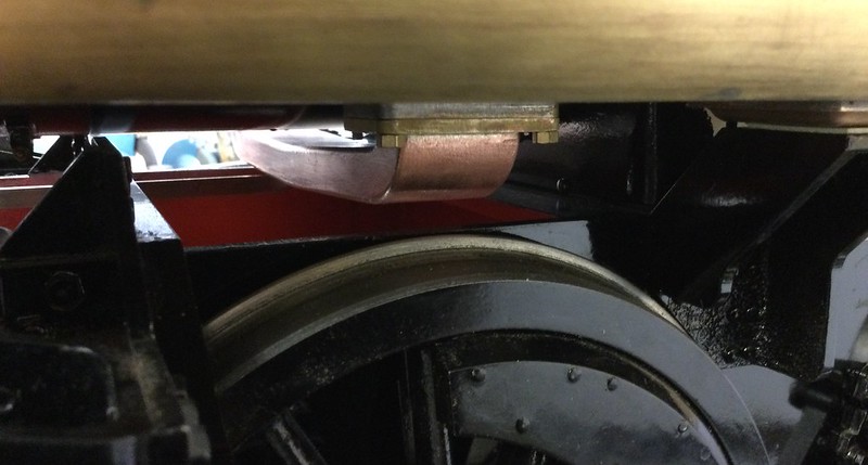 This photo clearly shows the clearance that is necessary under the boiler, as well as over the frames. Even if it is not quite to scale, it has the character of the original, and that is good enough for me. It was never going to be exact scale, because the original has 6 studs each side, mine has only 4 (and the inner ones are going to be quite fiddly to get the nuts on as it is!) They are not easy to see though, and even ' Inspector Meticulous' is unlikely to be examining them with a works blueprint in one hand; and if he does- too bad! The photo gives the impression that the pipe might be vulnerable to being struck by the flanges of the centre driver under max. spring deflection, but I hope this won't happen in practice. At the moment the springs are not adjusted, indeed thay are rather slack, so they are close to full deflection under static load. Something to keep an eye on for later though. |
|
|
|
Post by Roger on Feb 6, 2022 12:24:57 GMT
I really like that balance pipe, it's quite prominent, so definitely worth getting close to scale.
|
|
Gary L
Elder Statesman
Posts: 1,208
|
Post by Gary L on Feb 8, 2022 23:59:28 GMT
I really like that balance pipe, it's quite prominent, so definitely worth getting close to scale. Thanks Roger. I've since found that the surgery did reduce the 'length' of the Balance Pipe by 40 thou or so, but ovalising the holes in the flanges was enough to accommodate the difference (and incidentally make it easier to slide it over the studs.) Nobody will notice! The Balance Pipe can only be removed and refitted by first removing one or other of the tanks*, so having to take the tanks off was an opportunity to do some more trimming. First was a bit of bending at the innermost top front edge of each tank to support the widest part of the trim plates, which will be very thin (0.5mm). Don't want them to actually touch the boiler cleading anywhere, otherwise the expansion and contraction of the boiler will soon wear away the paint. The full-size tanks have two blacksmithed brackets near the front end to do this job, but in my case I can use the existing brasswork:  The uptilt is 7.5 degrees, measuring off the drawing, and the digital protractor helps get this right. It isn't really possible for me to bend the entire long edge, nor is it necessary. I just cut towards the bend line in four places with the junior hacksaw to make four tabs, then it was easy to make the necessary slight bend in each, one by one, using the toolmakers clamps to define the bend line and give the necessary leverage. The two tabs that perform the function of the steel brackets on the original are ¾" wide, the others are as they come. After that, I took the tanks to the mill and drilled through the previously spotted holes that are needed to secure the mounting blocks for the cross-tie girders. As mentioned before, the originals are welded to the tanks, and that is not feasible. After much thought, I decided to use R/H 6BA screws, backed up with soft-solder for extra security. Any visible slots can be filled, so the result will look like fat rivets, which is almost credible if you don't think too hard about how they might have been set (!) A little less obtrusive than hex screws anyway. Here is the solder paint going on. (I put the paint on both surfaces and the screwthreads BTW):  'And here's one I made earlier' at the rear end...  As in full-size, the Cross-Ties themselves will be secured with nuts and bolts.
*Because the drain plug gets in the way. If you don't want the drain plug, then omit it, and dismantling will be slightly easier. Adams replaces the prototype's drain plug with a horizontal hose barb for the supply to the axle pumps, but I have done away with those abominations. The hose connector would not interfere with removal, but the scaled drain plug does, because it protrudes at 45 degrees from the lower rear corner. I don't know if I will ever use the drain plug -if I want to drain Bridget's tanks I just use a rubber siphon tube- but nice to know it is there if needed. |
|


