|
|
Post by Roger on Feb 9, 2022 8:29:38 GMT
Attaching the balance pipe in a way that it can be removed easily is certainly a challenge. Fortunately you don't have to do this often when it's all been finished.
Your balance pipe looks spot on to me, nobody is ever going to say otherwise because you can't tell, and you have to get on your hands and knees to see where it connects anyway.
I don't think draining a tank is worthy of much consideration to be honest. If it can be done easily, all well and good, but it's not a deal breaker. You can always take a tank off outside and just let it run wherever it likes.
Cracking progress, this is really starting to look good.
|
|
Gary L
Elder Statesman

Posts: 1,208
|
Post by Gary L on Feb 9, 2022 23:21:42 GMT
Attaching the balance pipe in a way that it can be removed easily is certainly a challenge. Fortunately you don't have to do this often when it's all been finished. Your balance pipe looks spot on to me, nobody is ever going to say otherwise because you can't tell, and you have to get on your hands and knees to see where it connects anyway. I don't think draining a tank is worthy of much consideration to be honest. If it can be done easily, all well and good, but it's not a deal breaker. You can always take a tank off outside and just let it run wherever it likes. Cracking progress, this is really starting to look good. Thanks Roger, it is all coming together quite nicely now. Not too much to do before the cab and tanks can be painted. I have found draining tanks before a journey is very important, if the loco travels in a car with folded seats. It only needs a valve to leak, or a connection to break, maybe unnoticed on the track, and you get home with soaking wet upholstery. You'll only do it once! I syphon my tanks dry before driving home as a matter of routine now. I agree the 'official' drain plug on the 15xx will not be very useful (too small, too hard to access) but you never know when an extra access point to a tank might be wanted for some gadget or other (boiler ditto). It's official purpose in full size was to collect and remove sludge at the lowest point in the system- I hope I never need it for that purpose! Gary |
|
|
|
Post by Cro on Feb 10, 2022 8:11:48 GMT
Gary,
Is there no way to add a drain plug to the balance pipe you have just fitted?
Adam
|
|
|
|
Post by Roger on Feb 10, 2022 9:19:28 GMT
Attaching the balance pipe in a way that it can be removed easily is certainly a challenge. Fortunately you don't have to do this often when it's all been finished. Your balance pipe looks spot on to me, nobody is ever going to say otherwise because you can't tell, and you have to get on your hands and knees to see where it connects anyway. I don't think draining a tank is worthy of much consideration to be honest. If it can be done easily, all well and good, but it's not a deal breaker. You can always take a tank off outside and just let it run wherever it likes. Cracking progress, this is really starting to look good. Thanks Roger, it is all coming together quite nicely now. Not too much to do before the cab and tanks can be painted. I have found draining tanks before a journey is very important, if the loco travels in a car with folded seats. It only needs a valve to leak, or a connection to break, maybe unnoticed on the track, and you get home with soaking wet upholstery. You'll only do it once! I syphon my tanks dry before driving home as a matter of routine now. I agree the 'official' drain plug on the 15xx will not be very useful (too small, too hard to access) but you never know when an extra access point to a tank might be wanted for some gadget or other (boiler ditto). It's official purpose in full size was to collect and remove sludge at the lowest point in the system- I hope I never need it for that purpose! Gary Hi Gary, I hadn't really thought about emptying the tanks for transportation purposes, maybe I need to add something for that. |
|
Gary L
Elder Statesman
Posts: 1,208
|
Post by Gary L on Feb 10, 2022 18:37:09 GMT
Gary, Is there no way to add a drain plug to the balance pipe you have just fitted? Adam Hi Adam Yes, it already has one! Though being to scale it is rather small, with ¼” thread IIRC. Enough to get the last dregs out for winter storage- it’s not a pipe I’d like to see burst! Gary |
|
Gary L
Elder Statesman
Posts: 1,208
|
Post by Gary L on Feb 10, 2022 18:46:52 GMT
Thanks Roger, it is all coming together quite nicely now. Not too much to do before the cab and tanks can be painted. I have found draining tanks before a journey is very important, if the loco travels in a car with folded seats. It only needs a valve to leak, or a connection to break, maybe unnoticed on the track, and you get home with soaking wet upholstery. You'll only do it once! I syphon my tanks dry before driving home as a matter of routine now. I agree the 'official' drain plug on the 15xx will not be very useful (too small, too hard to access) but you never know when an extra access point to a tank might be wanted for some gadget or other (boiler ditto). It's official purpose in full size was to collect and remove sludge at the lowest point in the system- I hope I never need it for that purpose! Gary Hi Gary, I hadn't really thought about emptying the tanks for transportation purposes, maybe I need to add something for that. Hi Roger A siphon tube is usually quick and fairly easy to get most of it out. I can’t remember, but if you are taking your feed water from the balance pipe, an alternative is to have a length of rubber pipe at one end of the feed pipe and pull it off when a deep drain is needed. You might find a lot of water can be drained off via the connection to your driving trolley. HTH Gary |
|
|
|
Post by Roger on Feb 10, 2022 19:05:24 GMT
Hi Gary, I hadn't really thought about emptying the tanks for transportation purposes, maybe I need to add something for that. Hi Roger A siphon tube is usually quick and fairly easy to get most of it out. I can’t remember, but if you are taking your feed water from the balance pipe, an alternative is to have a length of rubber pipe at one end of the feed pipe and pull it off when a deep drain is needed. You might find a lot of water can be drained off via the connection to your driving trolley. HTH Gary Hi Gary, A syphon might be the answer then. I have a feeling I'm going to need a non-return valve in the feed from the driving trolley so that the Tanks don't back fill the trolley tank. |
|
|
|
Post by andyhigham on Feb 10, 2022 20:21:12 GMT
If you turn on the injector valves, the tanks will drain. Injector overflow is also a good filling point for the boiler
|
|
Gary L
Elder Statesman
Posts: 1,208
|
Post by Gary L on Feb 11, 2022 14:16:38 GMT
If you turn on the injector valves, the tanks will drain. Injector overflow is also a good filling point for the boiler Very true. In fact a not-quite-turned-off water valve is a potent source of wet car interiors! They are a bit slow though, if you are in a hurry and have a full tank to drain. Gary |
|
|
|
Post by Roger on Feb 11, 2022 15:02:06 GMT
If you turn on the injector valves, the tanks will drain. Injector overflow is also a good filling point for the boiler Good point, although I'll have to pull the chains down on the overflow valves so that the water can escape. That's fine though, it's another solution. Who will be the first person to incorporate a crude ejector and syphon to the Blowdown Valve to drain them automatically during that process... Actually, just partially turning on the Steam to the Injectors would achieve something similar. That ought to speed up the process. |
|
|
|
Post by Cro on Feb 11, 2022 15:20:57 GMT
If you turn on the injector valves, the tanks will drain. Injector overflow is also a good filling point for the boiler Good point, although I'll have to pull the chains down on the overflow valves so that the water can escape. That's fine though, it's another solution. Who will be the first person to incorporate a crude ejector and syphon to the Blowdown Valve to drain them automatically during that process... Actually, just partially turning on the Steam to the Injectors would achieve something similar. That ought to speed up the process. I use the injectors just that way on my locos to empty them quicker but try to avoid doing it all the way just in case they suck in something they shouldn’t. Adam |
|
Gary L
Elder Statesman
Posts: 1,208
|
Post by Gary L on Feb 15, 2022 1:21:24 GMT
Another little detail job that could be done almost any time is the Ejector Exhaust Pipe, which makes its way prominently if not prettily along the top of the right hand tank from Spectacle Plate to Smokebox. Just a bit of pipe bending, what could go wrong? Here is how it looked on No 1500 in 1961:  Nerdy types will instantly notice  (as I did not, for the first attempt) that the curvature beside the Spectacle window is different from the other members of the class, including 1501 as preserved at the SVR (Yes, that was Mistake No 1!) The bends at top and bottom of the Spec Plate are quite tight, and I am using 3/16" thin wall pipe, so it was necessary to fill it with lead at this end to maintain the cross-section. A low-melting point substitute (Woods Metal) is often recommended, but I have completely failed to find any in an affordable quantity. Lead works fine, but it is hard to be completely sure it has all melted out when the job is finished. At this point I offered it up to the cab front, and Mistake No 2 dawned on me:  I am sure it dawned on you quicker than it dawned on me! Clue: look at the exit hole from the Spec Plate. You can just make out the nipple of the Ejector, waiting to be soldered onto the pipe on the other side of the Spectacle Plate...This needed a drastic rethink. Opening out the hole big enough to pass a normal 5/16" x 32 union nut was out of the question, so I decided to make a 'special'. I'm quite pleased with the result, but it took several hours of work, proceeding slowly and carefully. The idea was to make the maximum OD as close to the thread as I dared, (which turned out to be 23/64"). This meant using Phosphor Bronze, for maximum strength. Then a 2BA hexagon was cut into the diameter immediately beyond the normal 1/16" internal shoulder that bears on the nipple. Here is is, with the hexagon being cut ⅛" wide with a suitable Woodruff Cutter:  After this operation, it was returned to the lathe to be parted from the stock exactly where the hex ended. I also counterbored it from the rear; only an extra 1/64" on the diameter needed to accommodate the shank of the nipple, but enough to ensure no jamming. The hole in the Spec Plate had to be opened out from 8mm to 10mm with a step drill. These are wonderfully gentle tools for making clean holes in thin sheet, and it was possible to do it in-situ with no problems at all. Here, perched on the firebox, is the special Union Nut and nipple, attached to the Ejector:  Here is the final result assembled into place:  A perfect scale appearance is impossible, (It is anyway, because the boiler backhead and hence the Spec Plate height above it is not to scale) but form follows function, and I am happy with it. It is not hideously obtrusive. The smokebox end was straightforward by comparison, and the elbow (with internal connection to the Petticoat) was made and fitted long ago:  And here is a view of the whole thing:  There is a slight upward spring in the pipe, but that will be dealt with last. A P-clip is required (just one, it seems!) to secure the pipe to the tank at the exact mid-length of the tank. The pipe does not run parallel to the tank side, nor does the prototype, though the angle is slightly greater here because the pipe has to clear the rearmost cross-tie, which is wider than it should be due to the aforementioned overscale Backhead. ( Yes I know, I bang on about this quite regularly!) David Adams designed the firebox with parallel sides, no doubt for ease of fabrication, perhaps not foreseeing a time when most boilers would be made by professionals who have the skills to cope. But an oversize backhead is not a total negative, because it allows more room for overscale fingers to get to the controls. Also visible in the photo above is the completed tank Fascia Plate, with steps and handrail, though not yet sealed into place. I've only pickled the pipe ends enough to remove the Easiflo flux. There is little point in removing all the black oxide, because the pipe will be covered with something. And here is where the final Mistake bit me on the bum! On 1501 at the SVR, the pipe is lagged with pipe bandage. (I understand this was because bystanders objected to a cascade of hot sooty water when the ejector valve was opened, so the lagging is an attempt to reduce condensation in the very long pipe). I imagine a shower with sooty water was every bit as unpopular in the 1950s and 1960s as it is now, but available photos lack the resolution to be absolutely sure if the pipes were lagged or not in those days. There seems to be a roughness to the surface that suggests they might have been, if only for the safety of the firemen when clambering on the tank top to put the bag in the manhole. Anyway, the 3/16" pipe seems to be slightly underscale, and I'm not partial to burns or hot sooty showers myself, so I intend to put some sort of insulating covering on the pipe. I did this for the whistle pipe inside the cab, using black heat shrink sleeving. It doesn't have immense insulating properties, but it is neat and better than nothing. I thought I would improve on this for the Ejector Exhaust by underlaying the heatshrink with some cable-wrap braid. A test piece showed this worked well, gving a slightly textured surface, but indistinct enough to be ambiguous (just in case). The braid would improve the insulation a little, on the 'string vest' principle. A brilliant idea no doubt, but I forgot that the covering would have to pass over one or other of the union nuts at each end of the pipe!  The braid can be expanded quite easily (and unexpectedly) to pass the nuts: 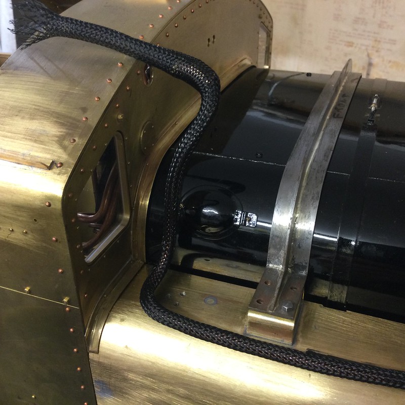 (It reminds me of those photos of a python swallowing a goat!) Unfortunately the heatshrink was not so obliging. The 2:1 that I was going to use will just pass the 'special' nut at the cab end, but it won't then go round the 90-degree bend as well. So I have ordered some 4:1 shrink, which I hope will do the job. 4:1 only seems to be available adhesive-lined, and almost certainly the adhesive will fill all the interstices on the braid, but beggars can't be choosers. It hasn't arrived yet, but I'll post a photo of the final result when it does. |
|
|
|
Post by Roger on Feb 15, 2022 7:37:46 GMT
Hi Gary,
That's a nice detail, one I'm yet to make. I also notice that the exit from the cab is different to 1501, which has two 'C' shaped covering pieces that fit the pipe closely. It's a good job you checked.
This will just be a dummy on mine. If I get round to fitting an ejector, it will be below the cab and probably exhaust there too.
|
|
Gary L
Elder Statesman
Posts: 1,208
|
Post by Gary L on Feb 15, 2022 14:42:35 GMT
Hi Gary, That's a nice detail, one I'm yet to make. I also notice that the exit from the cab is different to 1501, which has two 'C' shaped covering pieces that fit the pipe closely. It's a good job you checked. This will just be a dummy on mine. If I get round to fitting an ejector, it will be below the cab and probably exhaust there too. Hi Roger Yes, though it is in the Michael Caine category (“Not a lot of people know that!”). What all the class seemed to share was the blanked-off pipe exit below the active one. Occasionally I'm led to wonder what brought about the need for the change, though it doesn’t keep me awake at nights… Very few clubs run 5” carriages that are vac braked, and fewer still require a vacuum generator on the locomotive, so you are safe enough without one I reckon. It adds a degree of realism to driving in 7.25” gauge though, where masses involved are significantly greater. Vacuum systems are common there, though not universal, and possibly set to decline in proportion to the declining proportion of traction that is steam. (This is a UK comment, it is different elsewhere). As with injectors, it is very hard to fit a working device inside a scale outline, so maybe that should be your next challenge?  A tiny, and esoteric, disadvantage of the 15xx as a prototype is that they were never fitted with a vacuum pump. That spitting sound on every revolution of the wheels was unique to the GWR and is very evocative. I once tried to capture it on my Bridget, but with very short-lived effect. There is another challenge for somebody! Gary |
|
Gary L
Elder Statesman
Posts: 1,208
|
Post by Gary L on Feb 17, 2022 0:50:43 GMT
The frets for the tank trim plates arrived this morning from MEL; excellent, thanks Ed, I'll be dealing with them in the next instalment (probably):  But I had started on another piping job so I'll just bring you up to date on the Water Feed Pipes. The Safety Valves and Top Feeds were completed before I started this blog, but the pipes had to wait until the tanks were built, because they have to worm their way upwards through the conduit tubes built into the tanks. It is quite important to have all the pipes made before the platewok is painted, because othewise the multiple offerings-up would be sure to scratch the paintwork. There is nothing much to see here, (what can I say about making up pipes?) but there are a couple of suggestions for anyone else building a Pannier Tank. Here is a view of the assembled pipes:  Note how the RH pipe doesn't enter the conduit tube centrally. This is deliberate. The LH pipe demonstrates why, hopefully. It is just hooked on the three stainless studs that secure it and the clack box to the valve base. You need the max clearance available in the conduit pipe to persuade the clack box over the studs. The water delivery pipe is attached by a flange and two studs to the underside of the clack box; don't even think about using these as a dismantling/assembly break point, it doesn't work because there is unlikely to be enough clearance aver the boiler cleading. Old photos show the top feed pipes running quite snug to the top of the tanks, whereas on 1501 they take a more generous curve which arches them several inches above the tank top. This is undoubtedly to give a better flow through the pipes; the original sharp bend out of the conduit would have constricted the flow. Despite my preference to keep to the original layout where possible, this is one aspect where function trumps form in my view. Besides, my pipe bender produces the radius shown, and I see no point in changing it. I can't remember if I described what is happening inside the conduit pipe, so here is a view of the gubbins I made some while back:  There has to be a union to break the water pipe in the vicinity of the conduit pipe; the prototype has a flange joint just below the bottom end of the latter. What you see here is two unions connected by a few inches of nice hard Kunifer pipe that won't mind the torque. Making a virtue of necessity, the lower union incorporates a back-up clack (with ceramic ball, thanks for the tip Roger). The original idea came from LBSC's Speedy, though that did not have any clacks at the top feeds. The pipework is all ¼", while the proprietary injectors I am using have 3/16", so I doubt if there will be a problem with flow restriction. |
|
|
|
Post by Roger on Feb 17, 2022 7:27:50 GMT
Hi Gary,
That's looking realy good. You might want to make the bonnet before finalising the pipe runs, because the outlets from the bottom of the shoulders are really close to the boiler.
|
|
|
|
Post by Cro on Feb 17, 2022 8:07:40 GMT
Hi Gary, That's looking realy good. You might want to make the bonnet before finalising the pipe runs, because the outlets from the bottom of the shoulders are really close to the boiler. I have a drawing for it if its of use (I have started drawing it for the City and only yesterday was chatting to a guy who does spinning for me) but I had planned to cast it potentially. It's all looking great though, love it! Can't wait to see this and Rogers sat together. Adam |
|
Gary L
Elder Statesman
Posts: 1,208
|
Post by Gary L on Feb 18, 2022 0:10:51 GMT
Hi Gary, That's looking realy good. You might want to make the bonnet before finalising the pipe runs, because the outlets from the bottom of the shoulders are really close to the boiler. Hi Roger My main worry about the bonnet was that the pipes might be too high relative to the cleading, but I don’t think that will be an issue. The lower the pipes are, then the more cosmetic air space is available above them IYSWIM. It is only if they are too high, that things could get ugly (literally) but I think it will be OK. I’m going to do the bonnet last of all, because it is a self-contained job and doesn’t interfere with anything else, and if absolutely necessary, I can steam the loco without it. I don’t want to rush it, because it is the ‘crowning glory’ of any GWR/WR loco, and will repay a lot of care and time taken. Gary |
|
Gary L
Elder Statesman
Posts: 1,208
|
Post by Gary L on Feb 18, 2022 0:21:51 GMT
Hi Gary, That's looking realy good. You might want to make the bonnet before finalising the pipe runs, because the outlets from the bottom of the shoulders are really close to the boiler. I have a drawing for it if its of use (I have started drawing it for the City and only yesterday was chatting to a guy who does spinning for me) but I had planned to cast it potentially. It's all looking great though, love it! Can't wait to see this and Rogers sat together. Adam Thanks Adam, but I’m OK for a works drawing. I might be interested in a professional spinner if things go awry, but I have spun a number of items and I’m determined to have a go myself first. It will be the biggest job I’ll have done by far, and also the most prominent, so no hiding place! It would be a great privilege to ‘share a stage’ with Roger’s creation, but it would be Beauty and the Beast I fear; approach with caution! Gary |
|
Gary L
Elder Statesman
Posts: 1,208
|
Post by Gary L on Feb 18, 2022 2:07:12 GMT
A quick sequel to the Ejector Exhaust.The 4:1 heatshrink arrived this morning, so I conducted a swift test to make sure that the result would be what I wanted:  In the photo, a bent scrap of 3/16" copper tube. Above it, a short piece of the new heatshrink, which is supposed to shrink down to 4.5mm diameter (It doesn't, or not quite.) I was rather dismayed by the thickness of the material, even in its unshrunk state. At the LH end of the tube, propped up by the bender, the heatshrink is shrunk. You can see that the tube is not central because the heatshrink has not shrunk small enough to grip it, though the glue has flowed and filled the gap to hold the pipe securely. At right, the same thing, but shrunk on top of the black braid. This time, the increased diameter given by the braid has allowed a snug fit of the pipe within the shrink. As expected, the glue has filled all the interstices of the braid, but the shrink is so fat that all trace of texture from the braid has disappeared. In both cases the OD of the assembly is ⅜" or more, which is far too much, so the 4:1 heatshrink trial had to be abandoned. Thus it was back to the 2:1 non-glue heatshrink that I already had  and a re-think. I could not get it past the union nuts and the tight bends at each end of the pipe, much less with the braid in place as well; I had already established that. So the braid had to go too. Eventually a method dawned on my slow brain. I unsoldered the cone that retained the bigger of the two union nuts, and divided the 2:1 heatshrink into two lengths. The first length was wiggled (with difficulty) past the bends and onto the tube, and worked up to the far end and then some. This was then shrunk in place with a heat gun. One end was trimmed at the centre, exactly where the P-clip has to go, which will secure the middle of the pipe to the tank. Then the other length of heatshrink was likewise wiggled into place OVER the previous shrunk length. This was then covered with a wet rag, which was allowed to hang over part of the naked copper tube below it as well. This was to ensure that the unshrunk shrink (IYSWIM) would not get warm, because that would cause disaster:  The union nut was replaced, and the cone silver-soldered back onto the end of the pipe, taking care to keep the heat very local, and to dip the end in water the moment the solder had flashed. It was then possible to wiggle the still unshrunk shrink into place to cover the naked half of the pipe, and shrink that in turn. Then, with a razor, the overlap in the centre was cut through at exactly the place where the P-clip is to be, which will hide the joint from view. A final blast with the heat gun to tidy it all up. Note. It isn't easy to get a smooth shrink onto a 90-degree bend. The way to do it, is to confine the heat gun to the inside of the bend, while gently stretching and smoothing the hot material (with a dry non-linting rag- it gets very hot!) until it cools. Even this did not produce a perfect uncreased finish at the cab end of the pipe, where the bend is greater than 90 degrees, but hopefully it won't be too noticeable. So the final result looks like this:  A little bit more smoothing of the straight section will be in order, but that's it. Not quite what I'd hoped, but 'twill do. |
|


 (as I did not, for the first attempt) that the curvature beside the Spectacle window is different from the other members of the class, including 1501 as preserved at the SVR (Yes, that was Mistake No 1!)

 and a re-think. I could not get it past the union nuts and the tight bends at each end of the pipe, much less with the braid in place as well; I had already established that. So the braid had to go too.