cfmrc
Seasoned Member

Posts: 107
|
Post by cfmrc on Jan 22, 2022 16:30:19 GMT
I agree John that the Proxxon stuff is very good, their hand pieces are excellent, but the flexibility of John’s mill drill is amazing. He made it with a longer table for me and the rear column can be moved to accommodate different sized work. Including all the extras and bits he made such as a drilling head and a milling head; the price difference - with todays prices - is probably a lot less than you might think. The quality is incomparable; it has revolutionised my 2mm scale modelling.
Tim
|
|
cfmrc
Seasoned Member
Posts: 107
|
Post by cfmrc on Jan 23, 2022 21:46:51 GMT
The cab roof on Sir Sagramore has made some progress over the last two days. It is held by a tab at the front and the rear beam, as well as some 2mm diameter 1mm thick rare earth magnets. I may add a few more as they work quite well. The fit will improve when the rear beam is soft soldered to the roof and stiffens the corners where it engages. 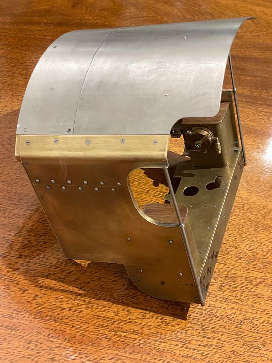 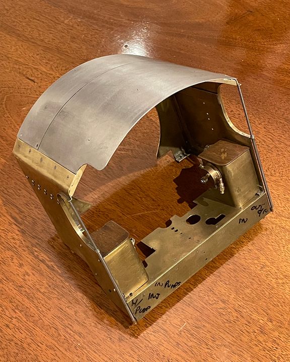 The rear section slides out and is held by the magnets whilst doing so. 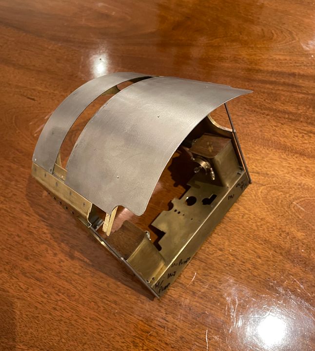 The rear beam has some brass brackets silver soldered to it to allow it to be bolted to the roof. I’ll soft solder it on when I’ve made the rain strips. I have some brass right angle strip but I think it’s too small. 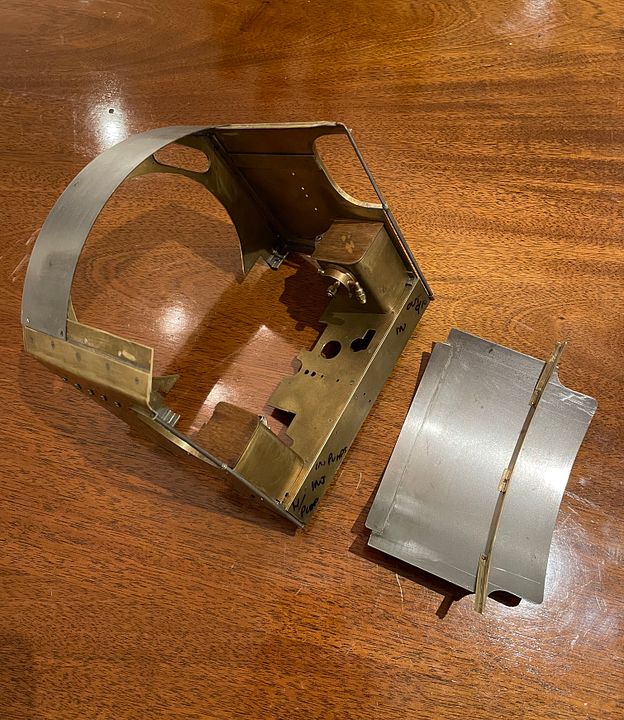 It begins to look like a Maunsell cab now and should transform the appearance of the engine when re-assembled. Tim |
|
cfmrc
Seasoned Member
Posts: 107
|
Post by cfmrc on Jan 25, 2022 22:13:10 GMT
The back of the cab retaining beam has been stiffened and fettled a bit more so the removable roof is now settled down in the correct place. 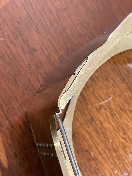 The cab roof has some subtle little eyebrows on the front corners so adding these has also tidied-up this area. 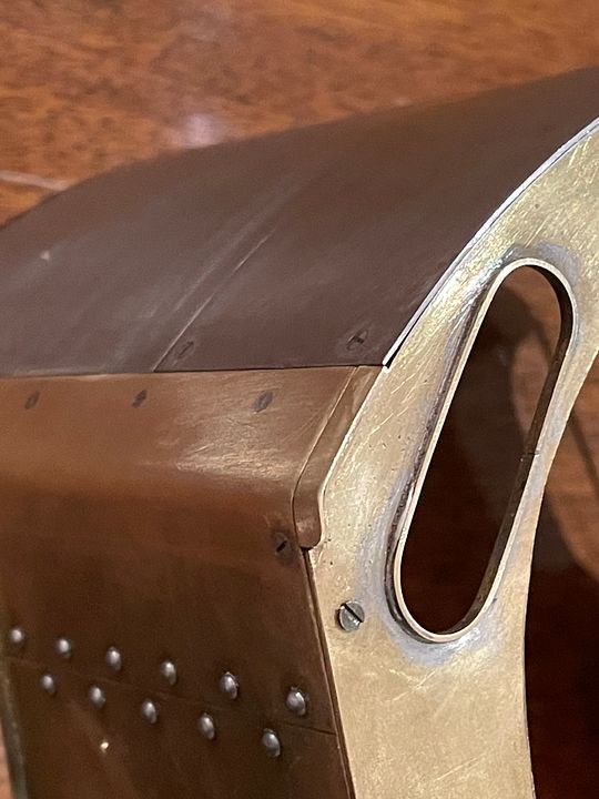 The window frames probably need thinning down a bit, but Sir Percivale won’t get the Dennis Healey eyebrows which were later fitted to the King Arthurs. 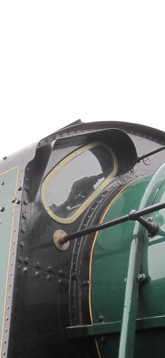
(photo courtesy Derek Pollard) It’s very noticeable that the handrail stanchions and rain strips are quite fine. There are also an awful lot of bolts, but the engines were generally smoother when built. Tim |
|
|
|
Post by keith1500 on Jan 26, 2022 7:23:50 GMT
What was the purpose of these “eyebrows “ just keep the rain off or did they improve visibility as the spectacle glass is square to the cab?
|
|
cfmrc
Seasoned Member
Posts: 107
|
Post by cfmrc on Jan 26, 2022 9:27:20 GMT
No real idea why they were fitted, but they would have done both of those things. They certainly don’t improve the clean lines of the design.
Tim
|
|
|
|
Post by keith1500 on Jan 26, 2022 13:35:07 GMT
Yes it’s interesting how these features change the look of a locomotive. They make the German locos look very business like along with the pipe work etc. where as smoke deflectors on Scotsman again changes it’s look.
Nice detail on your model. And I hadn’t realised the radius of the spectacle glass doesn't follow the boiler until you posted the photo.
|
|
cfmrc
Seasoned Member
Posts: 107
|
Post by cfmrc on Jan 27, 2022 8:44:38 GMT
Of course, 772, Sir Percivale, was fitted with large Germanic deflectors in the late 20s. This did nothing for the looks, but the Southern settled for what later became their typical deflectors a little later. Holcroft visited Germany and so the Dennis Healey eyebrows may have been a function of that visit.
Ian Jaycroft made a set of smoke deflectors for the engine, but I much prefer the clean-lined original.
I will probably change the shape of the window frames a little: they should be slightly curved at the top: I have a cunning plan for this.
Tim
|
|
cfmrc
Seasoned Member
Posts: 107
|
Post by cfmrc on Jan 31, 2022 15:37:18 GMT
The rain strips on the cab roof have now been made from 1.5mm angle brass. One of the challenges is that they have quite a sharp curve at the rear end where they change direction. After bending up the vertical curve of the cab roof between fingers and thumbs some fine slots were cut in the bottom of the strip using a very fine cut razor saw. 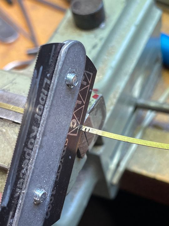 These slots were then opened out to a more triangular shape using a slotting file. 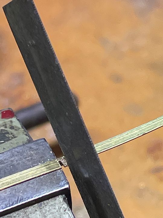 The corner was then bent up and pilot (tapping size) holes drilled in the brass angle where strategically required to keep everything in place. The underside was also tinned. 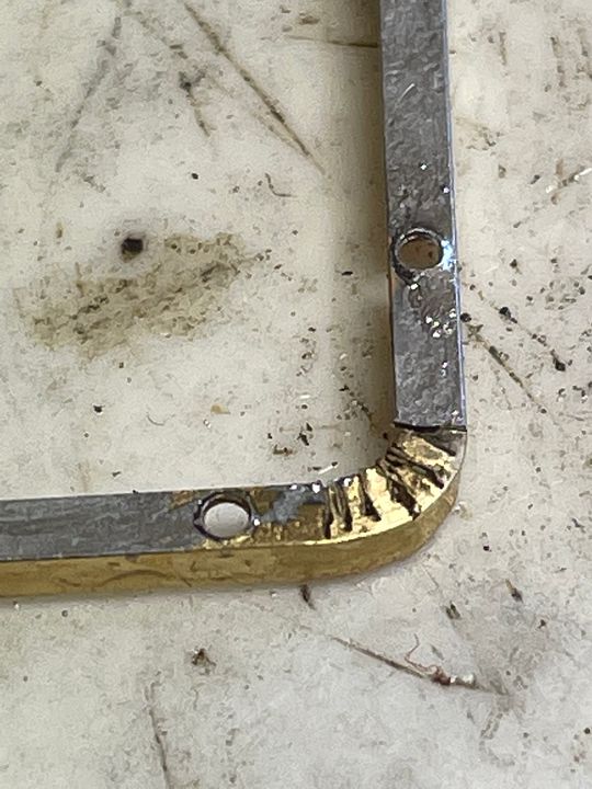 The corner was located on the cab roof and one hole drilled through the steel at clearance size through the steel roof. The brass was tapped 14BA and the rain strip located with a suitable bolt. After this stage, the second hole was drilled at tapping size and if required for alignment ‘stretched’ in the right direction using a needle file, as seen in this image: 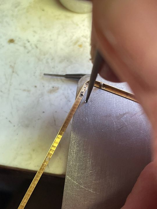 After the alignment was OK, other holes were drilled at tapping size and then tapped through the brass and steel together. 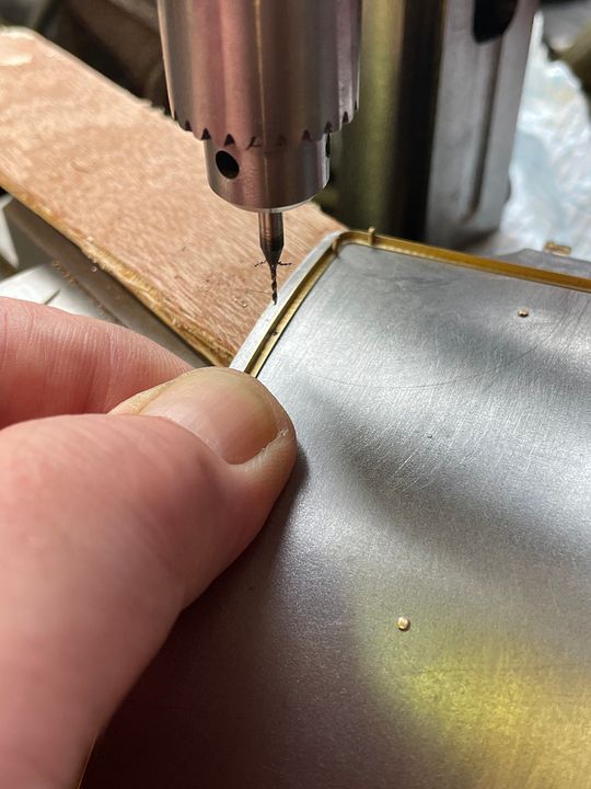 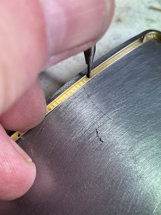 Any slight errors in alignment could be accommodated by ‘moving’ the hole in the steel roof, when it was being opened up for clearance. Once the whole lot was in place a very hot soldering iron was used to sweat everything together. With the rain strips soldered in place the bolts heads and shanks were cut off and tidied up with a riffler file. This also helped to get rid of the machining marks on the brass. 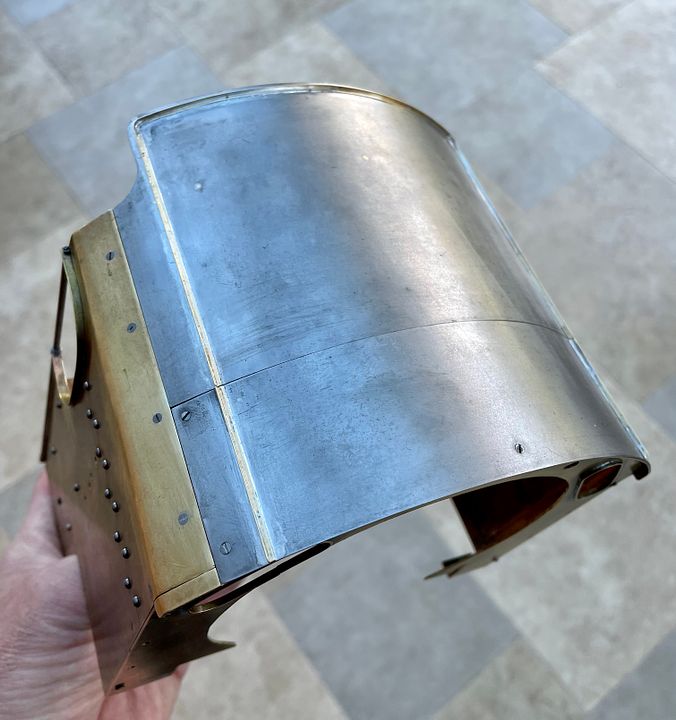 The rain strips are suitably subtle and the little tongues in the corners inconspicuous once cleaned up. 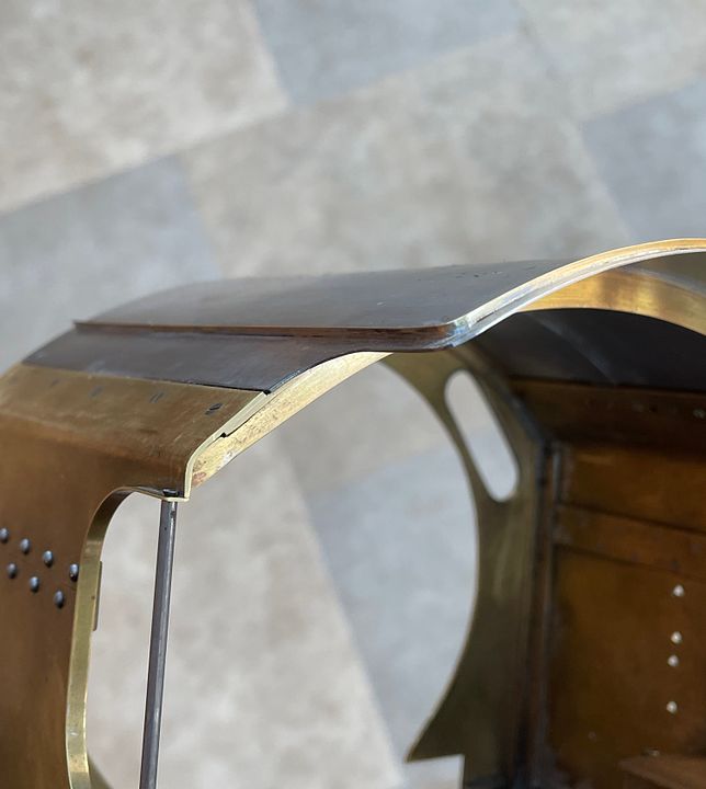 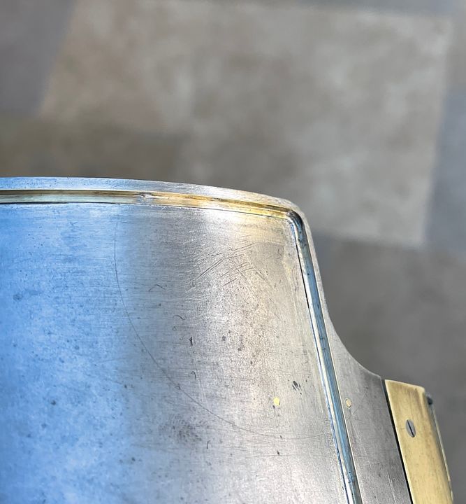 Last thing to do on the roof will be two little handles. 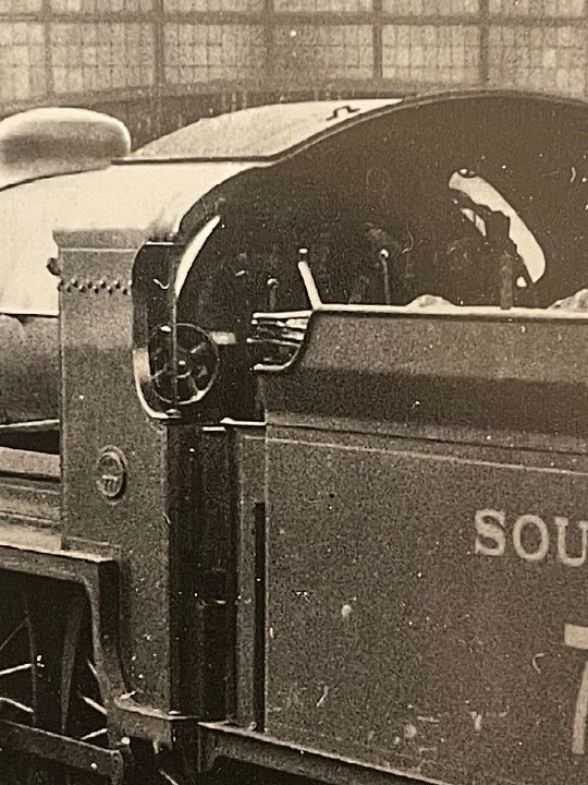 Tim |
|
cfmrc
Seasoned Member
Posts: 107
|
Post by cfmrc on Feb 1, 2022 19:54:15 GMT
Inside every lump of metal there is a shape trying to come out - actually two in this case. 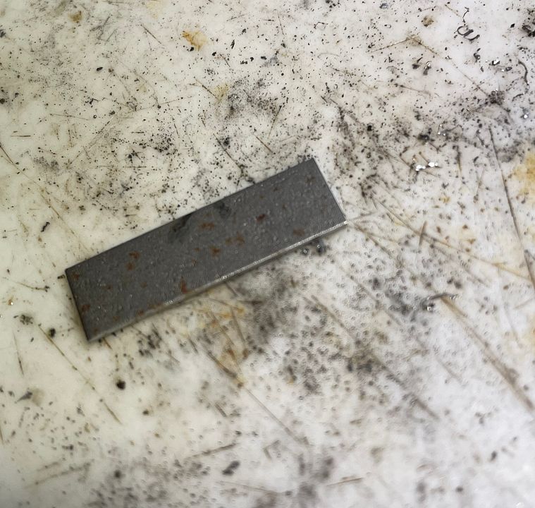 The cab roof handles would probably have helped positioning when the rear was removed for maintenance purposes ( on the prototype). 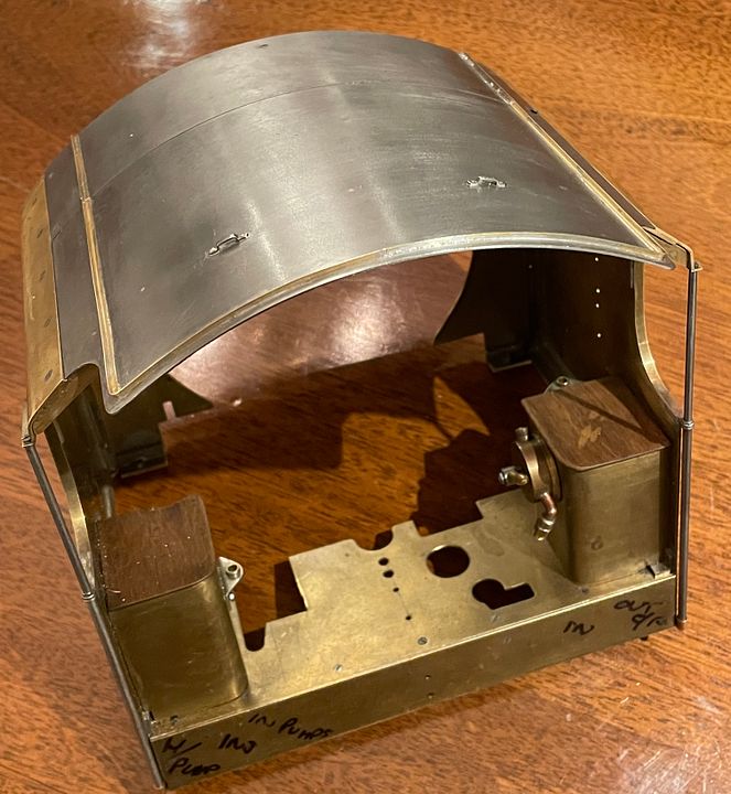 The metal strip was bent to shape, drilled 0.8mm x 4 and then sliced into two handles. These were tapped 14BA and held in place with bolts whilst soldering. 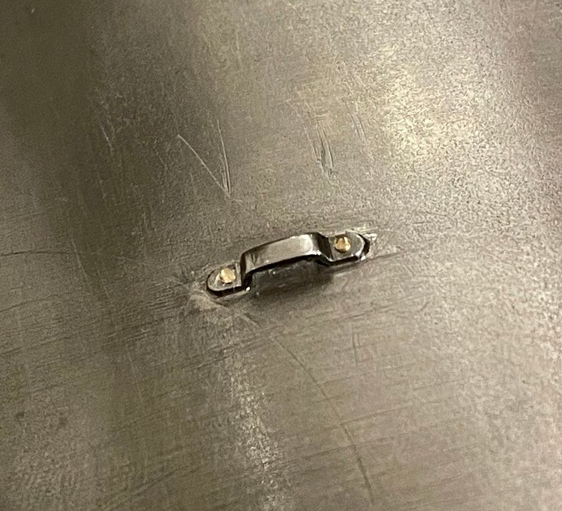 That’s the roof done. Tim |
|
cfmrc
Seasoned Member
Posts: 107
|
Post by cfmrc on Feb 4, 2022 17:05:31 GMT
Maunsell cabs did have a slightly ‘hang dog’ look to the front spectacle plate. This wasn’t quite correct on Sir Sagramore, with the windows being parallel-sided. 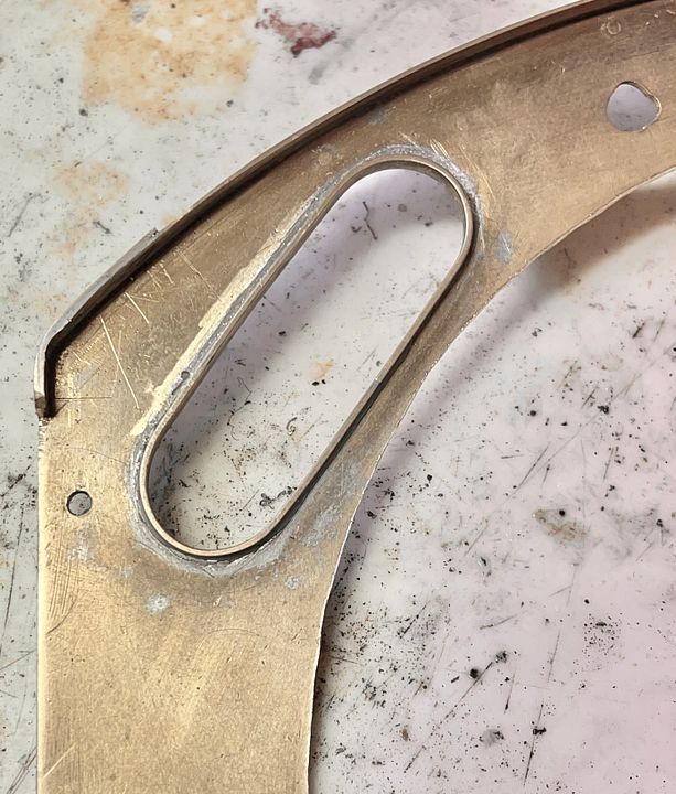 I therefore used a piercing saw to make space to enlarge the window a bit. 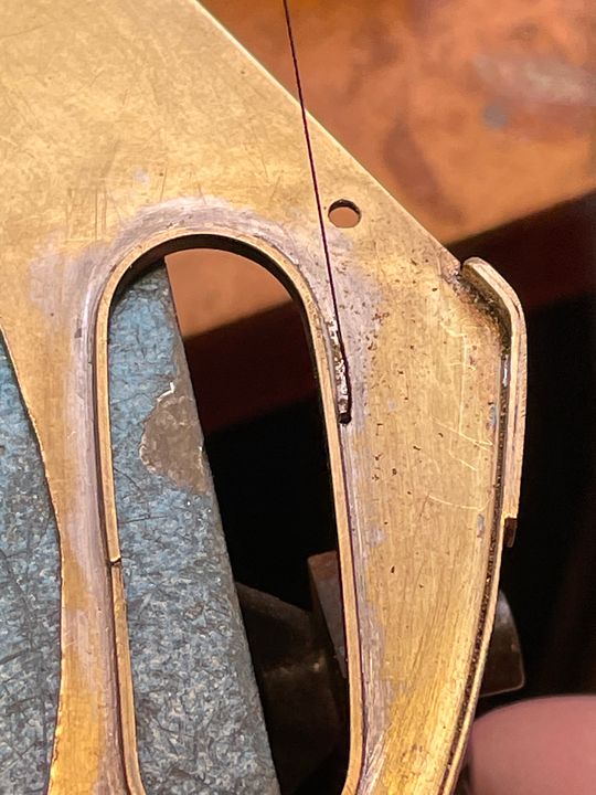 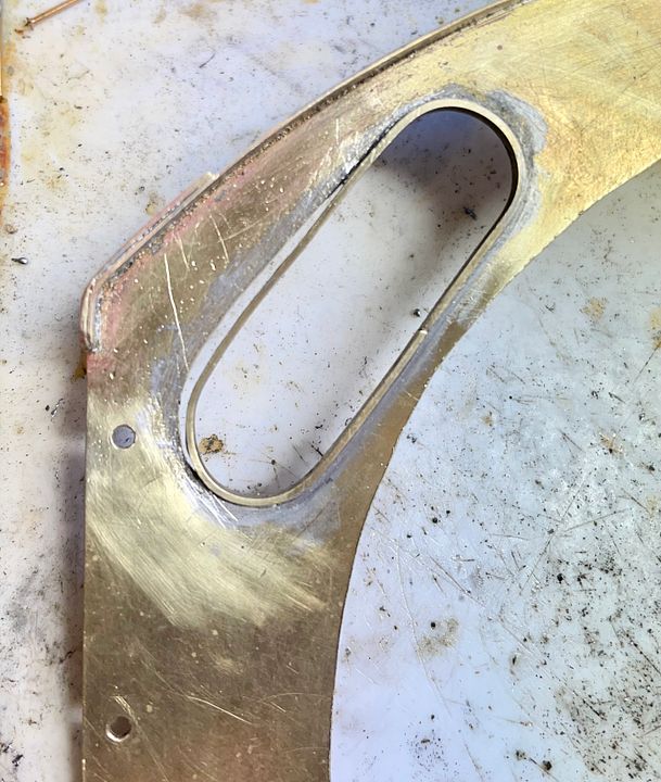 The window frame was then swaged into the correct shape. 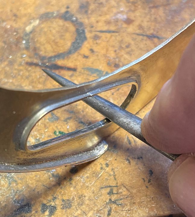 The end result is subtly different and probably worth the effort. 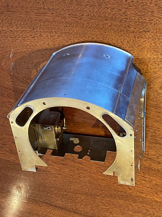 There are a whole load of rivets / bolts needed in this area. 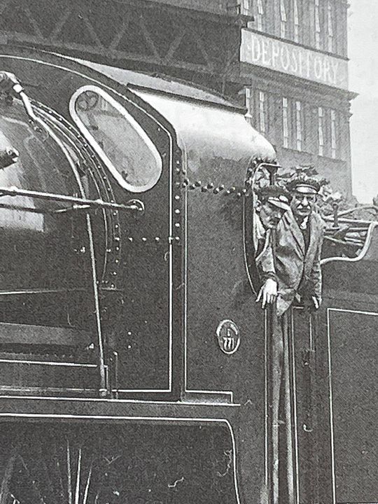 Just need to find where I put that tobacco tin… Tim |
|
cfmrc
Seasoned Member
Posts: 107
|
Post by cfmrc on Feb 11, 2022 18:48:24 GMT
Today was the day of the rivet / bolt for Sir Sagramore. On the prototype, the top of the cab was designed to be removable for improved access during heavy shoppings. Most of the bolts representing the fixings are round headed 10BA, permanently fixed and dummy, but some are slotted to allow dismantling the cab. 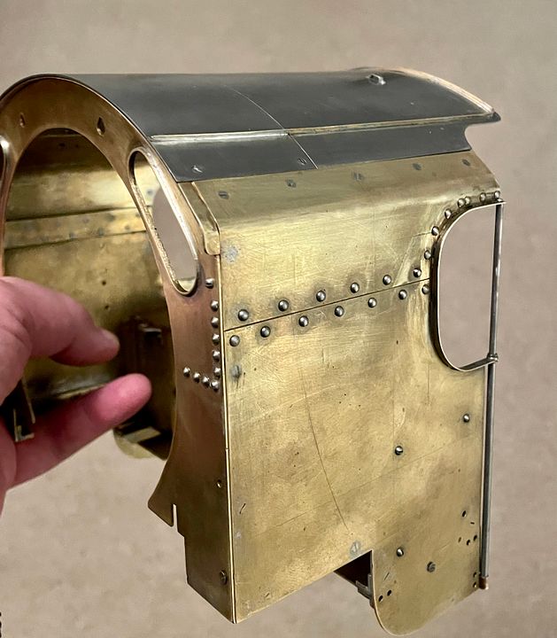 It will make lining out a bit more challenging but shouldn’t be too bad, considering the fairly large scale. Tim |
|
cfmrc
Seasoned Member
Posts: 107
|
Post by cfmrc on Feb 15, 2022 0:49:55 GMT
I have re-united the cab with the rest of the loco, returning to the rather cooler big workshop to do so. It still fits! 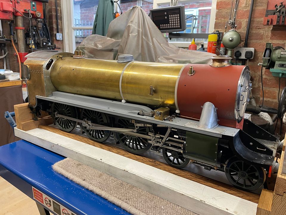 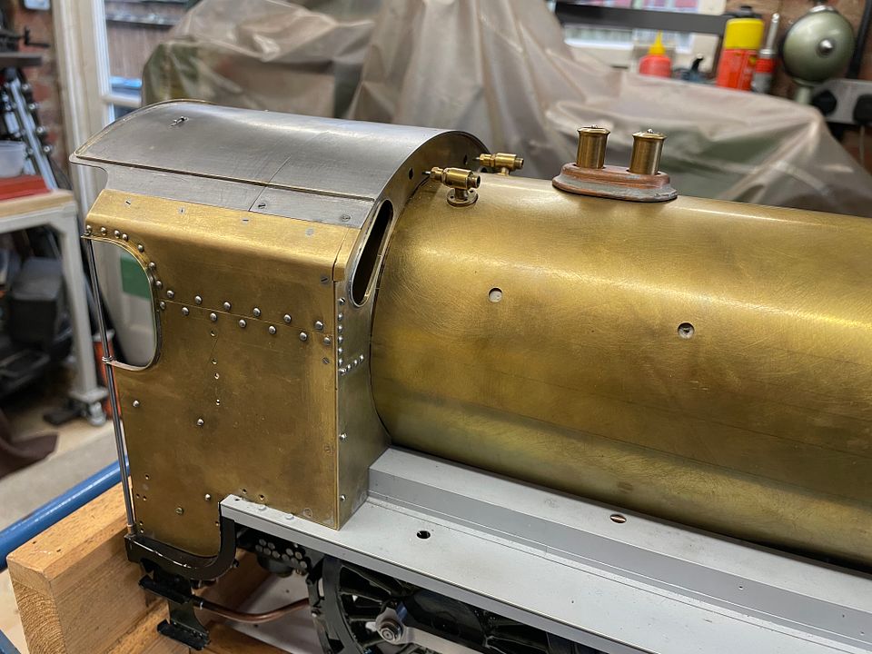  Tim |
|
cfmrc
Seasoned Member
Posts: 107
|
Post by cfmrc on Feb 18, 2022 19:19:04 GMT
The original name, Sir Percivale, is no more, he’s changing to Sir Sagramore. The only surviving engine of the class, Sir Lamiel, is undergoing a major restoration. www.sirlamiel.org.uk/index.php/2022/02/10/777-sir-lamiel-progress-report/I therefore thought it a very good cause to help a little, so I’ve joined the funding round table. This has meant that the engine has changed name, Sir Sagramore being an available name that I could use and an engine that was photographed many times when new. 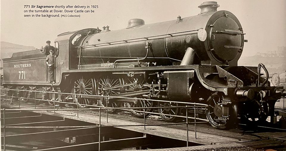 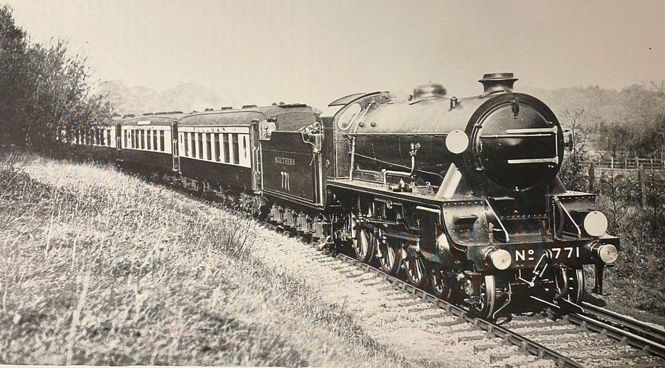 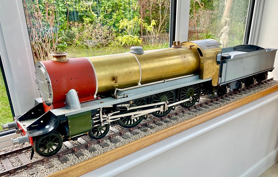 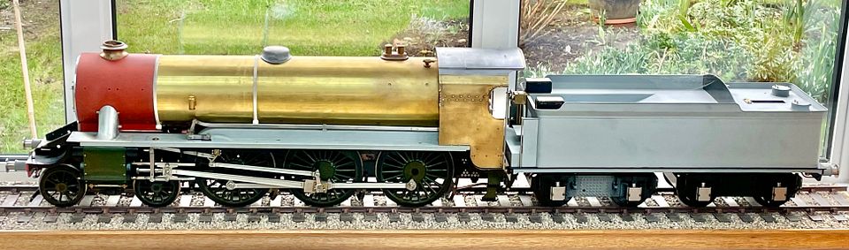 The engine is looking quite racy with the full cab. In true Stalinesque form, I have airbrushed out the old name In previous posts… Tim |
|
cfmrc
Seasoned Member
Posts: 107
|
Post by cfmrc on Oct 10, 2022 11:00:00 GMT
After a bit of a diversion to other bigger and smaller projects, I have returned to the NBL works. Sir Sagramore has a hydrostatic lubricator, which needed a 180 deg (in line) globe valve to isolate the steam feed when required. Commercial examples are rather crude. Ian Jaycroft had made the top half of a valve but I couldn’t find the globe itself in any of the bits bags. The bottom half was turned up in the lathe with a small hole for the valve seat and a larger tapped hole for the valve spindle body. 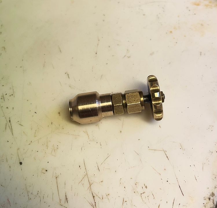 This was set up in the drill, having filed two flats on the sides of the valve body. The angled holes were drilled by eye. 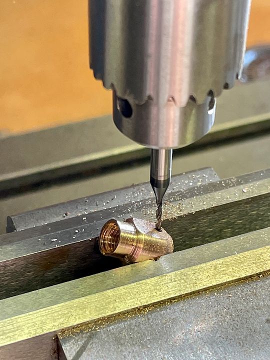 The gods were being benevolent as both holes ended up in the correct place. 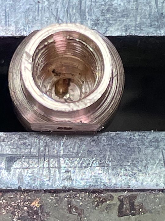 Two pipes, threaded 3/32” 60ME, with a flared base were made. The openings to the valve chamber were also increased in size with a dental bur. These were then blocked off with Tippex and the assembly clamped together. 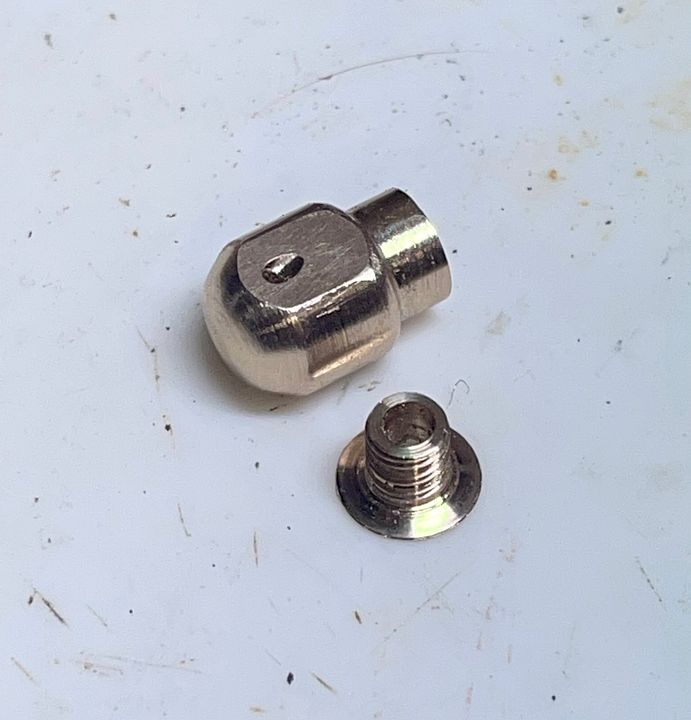 Two large endodontic files were used to open out the feed and delivery channels, visible above and below one another. 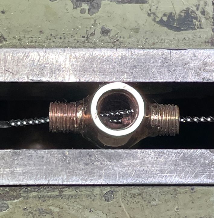 The sub assemblies can now be seen. After silver soldering the shape of the valve was established using burs, stones and abrasive rubbers. 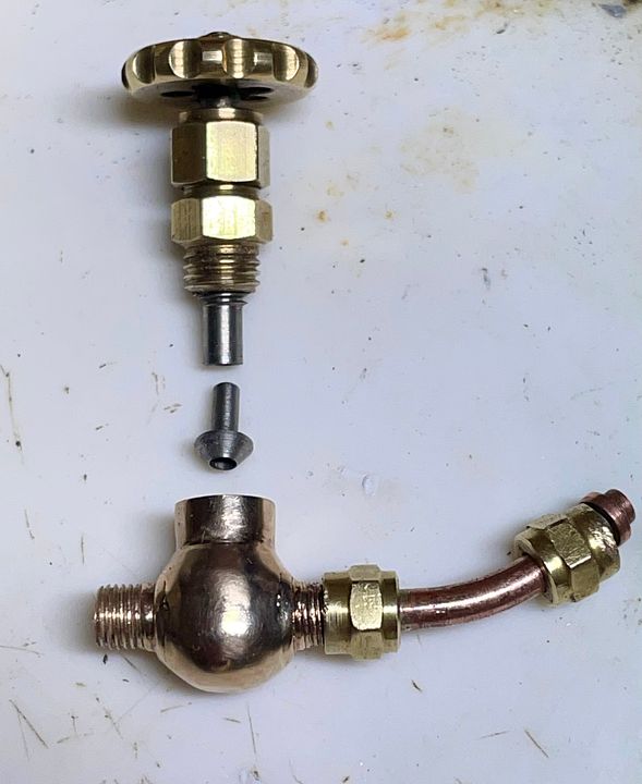 The delivery hole can be seen at the top of the pipe. 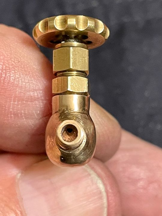 There may be ‘proper’ ways of making globe valves, but this one passes the ‘puff’ test. 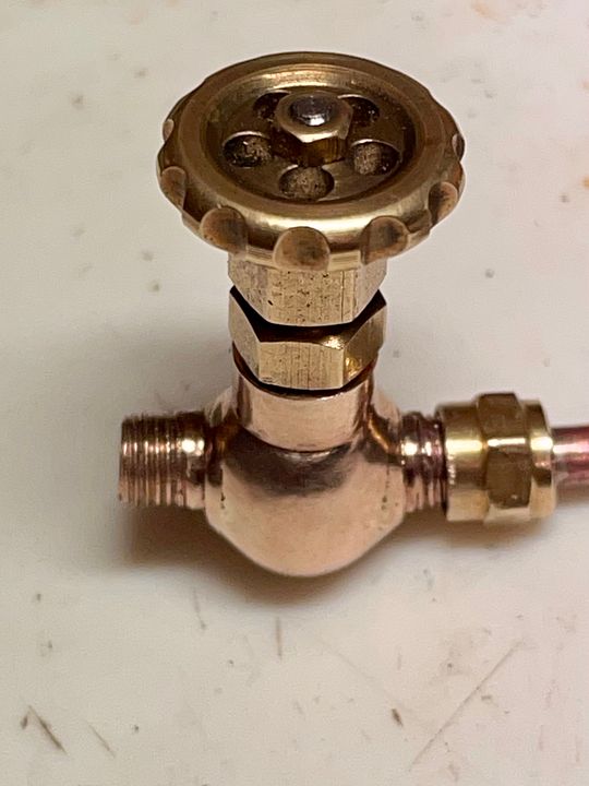 Tim |
|
cfmrc
Seasoned Member
Posts: 107
|
Post by cfmrc on Oct 11, 2022 7:37:15 GMT
It’s quite difficult to work out how someone else intended to make an incomplete model. The livesteam manifold on Sir Sagramore clearly needed two plugs at each end but it was only fairly thin copper pipe that they could fix into. Using silver solder at this late stage would have been much too risky for the assembly. Consensus at the NLSME was that if a high temp soft solder was to be used then a screw thread would be advisable to give auxiliary retention to hold the plug. 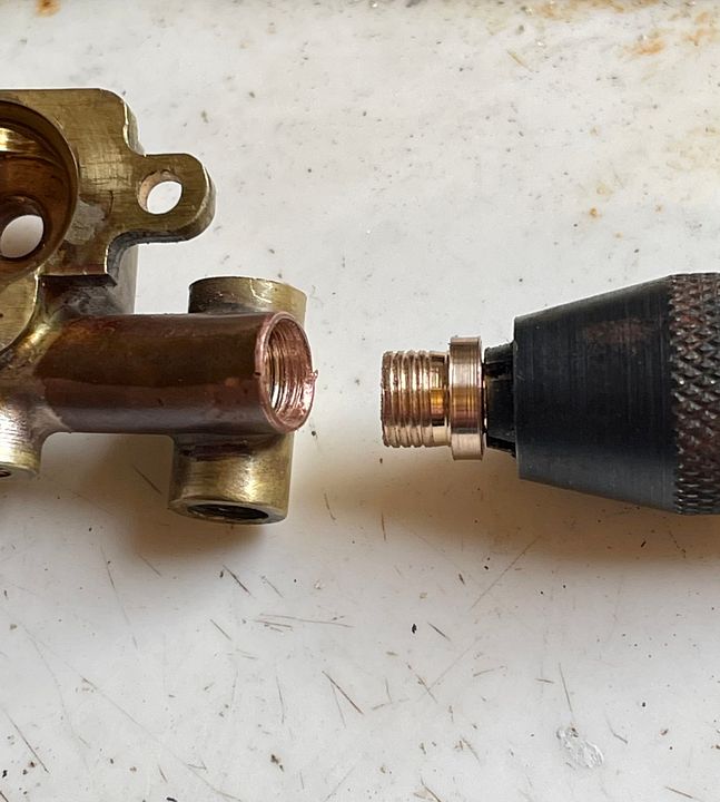 The pipe just about took a 7/32” 40 TPI ME thread, but a plug made to that size was much too loose (A 1/4” 40 ME tap would have been much too big for the wall thickness). The solution was to make a 1/4” 40 ME plug with the die tightened up and wind it in with force using a large pin chuck. This swaged the copper pipe, increasing its size for the plug which was then soft soldered in place with Comsol. 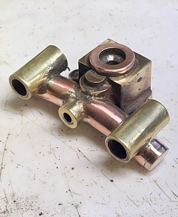 The expanded pipe size is just discernible on the RHS 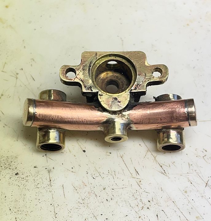 Bit naughty really, but there is no way those plugs are coming out any time soon. Tim |
|
cfmrc
Seasoned Member
Posts: 107
|
Post by cfmrc on Oct 13, 2022 22:51:42 GMT
The original injector steam feed pipes had an un-prototypical swan neck exit from the boiler valve. 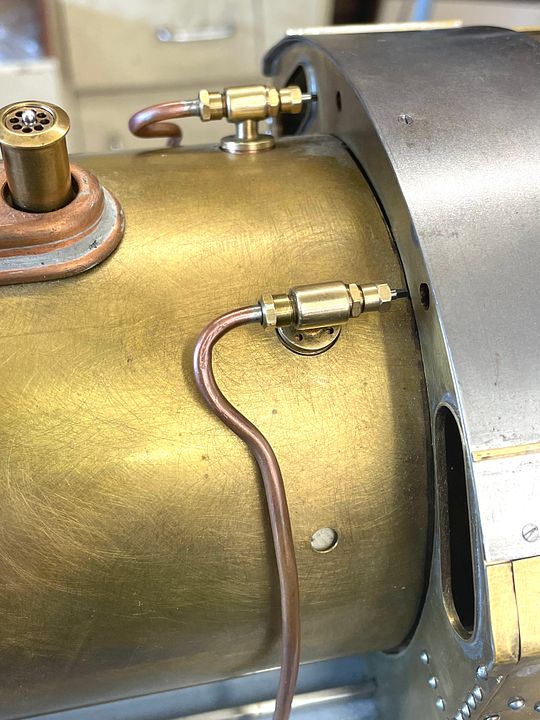 I therefore made a right angle fitting to neaten up the plumbing. 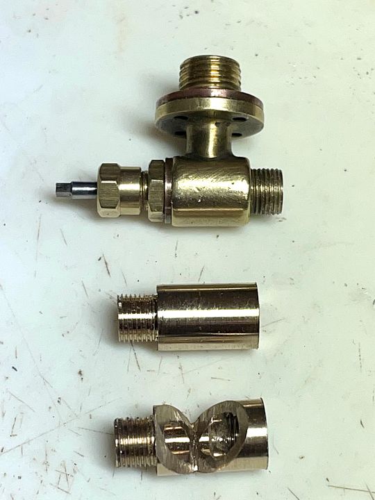 Original valve at the top. The right angle extension was threaded 3/16” 60 TPI ME at each end. A 90 degree chunk of metal was removed with a diamond slitting It was bent to shape with frequent annealing and then silver soldered. 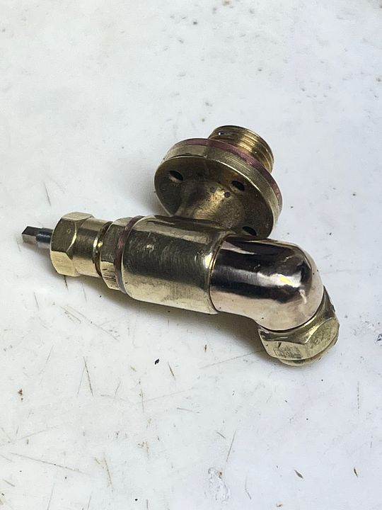 Still not strictly correct, but Ian’s original valves are a work of art which I wanted to keep. 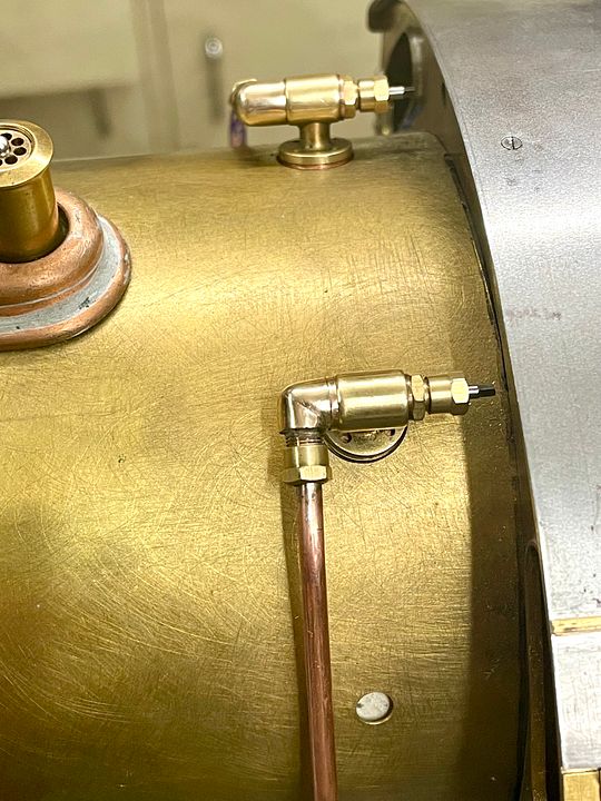 Tim |
|
cfmrc
Seasoned Member
Posts: 107
|
Post by cfmrc on Oct 18, 2022 7:36:30 GMT
The injectors on Sir Sagramore were originally partially made by Ian Jaycroft. Unfortunately, both were incomplete and a challenge to finish. 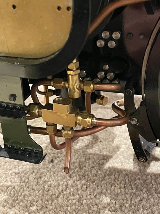 On the RHS I have therefore fitted a ’Chiverton’ 16oz injector from Paul Pavier. The water feed pipe to the boiler clack had a right angle fitting made, a requirement of having limited space. The internal passage is polished to aid water flow. 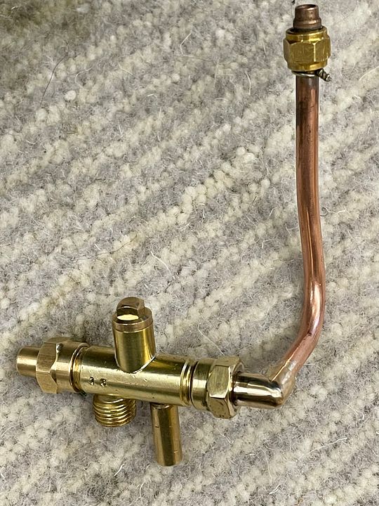 The injector has fairly large fixings so it is placed low down (as per prototype) and has a simplified water supply. The bottom water feed pipe again has a bespoke 90degree fitting to keep the plumbing neat. 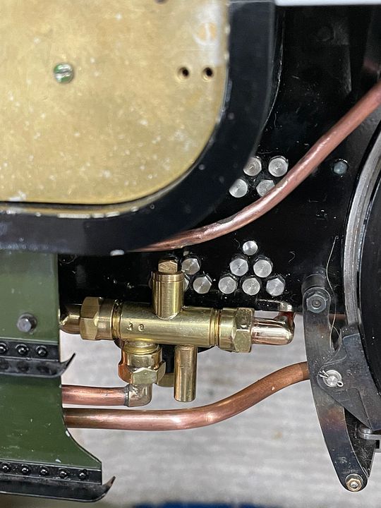 The moth-eaten steam supply pipe at the top is just a placeholder: I’m awaiting some more 1/8” pipe to reinstate this. 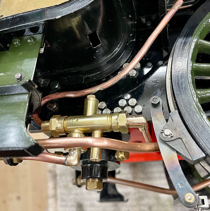 There will be a discrete accessible water control valve fitted in the tender giving a well streamlined water flow. 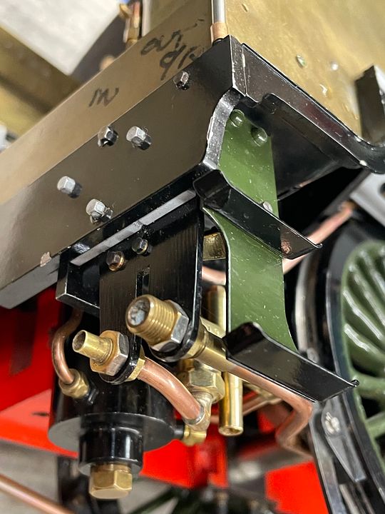 Ian’s original set up with the incomplete miniature injector had plumbing that was a bit of a snakes wedding, with generally rather small bore pipes for the water feed. The handle for the water control valve was very small and quite inaccessible within the cab. I may, however, try Ian’s arrangement (duplicated) on the LHS, where access to the water valve is better, as the engine only needs one reliable working injector, there also being hand and axle driven pumps to get water in the boiler. Reverse engineering the injector could be very challenging, but probably worth a go. Tim |
|
cfmrc
Seasoned Member
Posts: 107
|
Post by cfmrc on Nov 6, 2022 0:01:49 GMT
Attention has now turned to the steam supply to the oil reservoir of the sight feed lubricator. This pipe was roughed out for shape with some thick electrical single core cable. 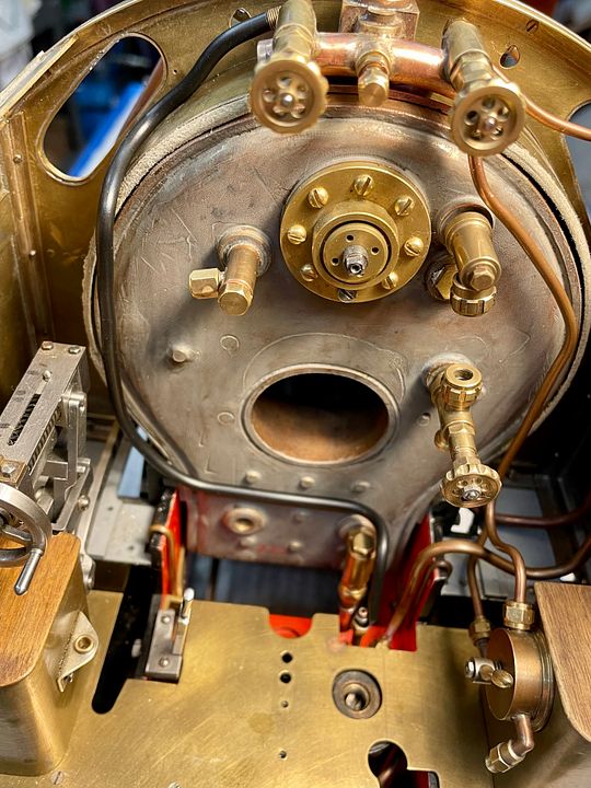 The actual pipe was made in two halves with the little globe valve in the middle. The bending was done by hand with frequent annealing. 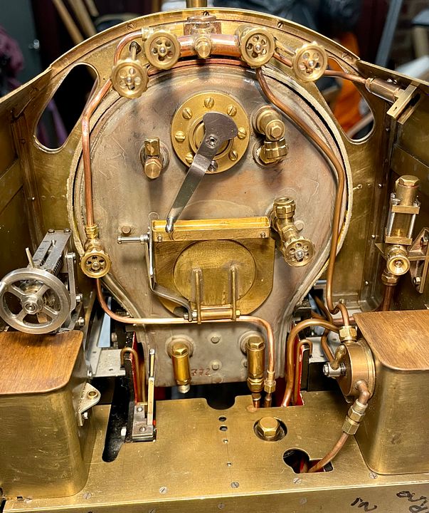 I couldn’t resist putting in place some of the other fittings. The backhead will have a false cover, to which will be attached the firebox door, pressure gauge, and injector steam valves. The round head bolts on the regulator gland will be replaced with something more appropriate. Tim |
|
cfmrc
Seasoned Member
Posts: 107
|
Post by cfmrc on Nov 8, 2022 8:00:55 GMT
The back head cleading was initially sketched out using a paper template. 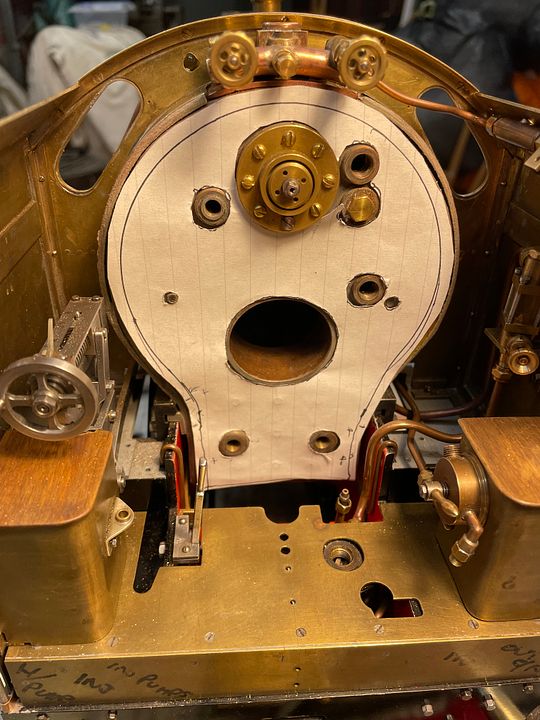 This was then transferred to 0.6mm thick brass and cut out using a dental engine, a diamond disc and TC trimmers. 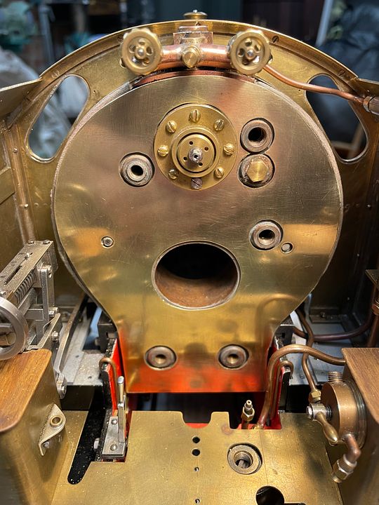 Ian Jaycroft made a superb quarter-round brass bezel. 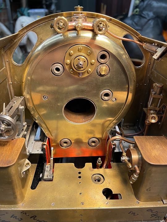 The two components will be soldered together to make a more solid structure, so that there aren’t any gaps. The firebox door assembly (visible in the previous posts) will be bolted through the cleading. 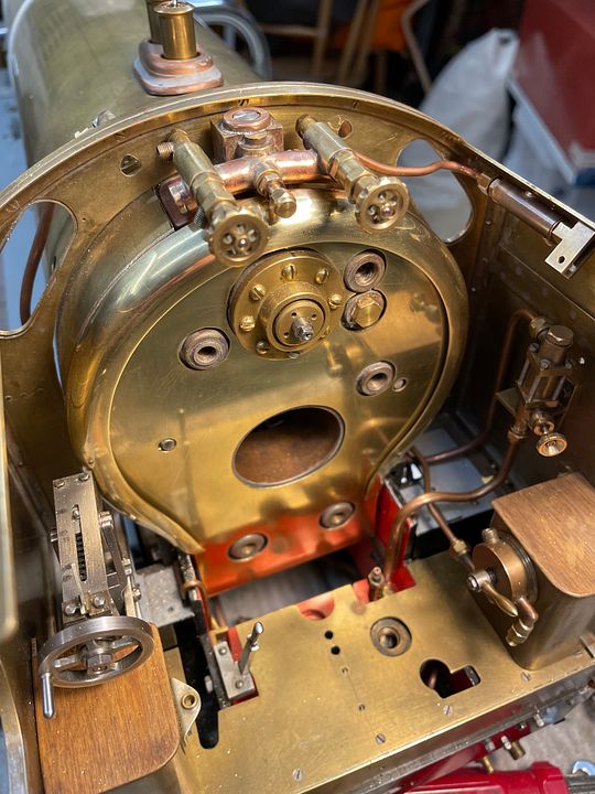 Tim |
|
|
|
Post by suctionhose on Nov 8, 2022 23:30:14 GMT
I feel compelled to say, given the engine is only 3 1/2"g, your workmanship is extremely neat and well finished! The cab and controls are beautifully refined. I really enjoy the pictures. Will be a shame to hide it under paint!
|
|


