dalboy
E-xcellent poster

Posts: 235
|
Post by dalboy on May 16, 2022 16:04:33 GMT
Spent today making up a jig/fixture to quarter the wheels I am trying to keep it simple. I cut two pieces of ali plate 10mm thick and squared it all around to 3.750" found the centre and drilled and tapped a hole through both at the same time this was tapped to 5mm as that is what I had in a screw for the purpose I needed it for. From that centre I marked and drilled the offset equal to the offset of the crank pins followed by reaming it to 1/4" the same as the pins. Took a few photos to give an idea how the set up will work once complete. Because I squared each plate by turning one 90deg will give the correct angle for quartering. The two screw threads will have a point machined to go into the centre of the axles by slackening them off a fraction at a time while pressing the assembly together should keep everything in line I will be doing this on a surface plate to keep the jig from twisting.  DSCF2520 DSCF2520 by Dalboy, on Flickr  DSCF2521 DSCF2521 by Dalboy, on Flickr  DSCF2522 DSCF2522 by Dalboy, on Flickr |
|
dalboy
E-xcellent poster
Posts: 235
|
Post by dalboy on May 16, 2022 20:07:29 GMT
After taking the pictures I have decided that a little modification to the jig is needed will try tomorrow
Does it matter which way the quartering is done clockwise or anti clockwise or will this make no difference as long as all sets are done the same way
|
|
uuu
Elder Statesman
 your message here...
Posts: 2,807
|
Post by uuu on May 16, 2022 20:43:50 GMT
I doesn't matter for how it works. But if you get it wrong you'll hear it from every passing pedant. Most locos are right hand lead so the cranks on the right side are ahead of those on the left in forward motion. Hopefully someone will jump in quickly if Rob Roy is unusual.
Wilf
|
|
|
|
Post by Rex Hanman on May 17, 2022 11:51:29 GMT
Phil, I think I gave wrong info on the piping recommendation. The piping I am referring to is the very short section between the valve chests. I am working from memory, and I am not sure if it was exhaust or intake. Sorry for the confusion. Rick Like this.... 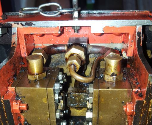 It's so much easier than struggling to get the short piece of pipe between the steam chest covers. The pipe with the u-bend is the oil feed from the lubricator. Hope this helps, Rex |
|
|
|
Post by philh1aa on May 18, 2022 18:33:32 GMT
Rex,
Very helpful for me. I was planning a very similar pipework arrangement/ connection. I never ever have any luck with screwed pipework connections whether it was as an apprentice with decent sized pipes or the bloody central heating system at home. I plan to use mainly soldered joints with O ring seals at the front of the steam chest. The flanges of the O ring joint will be held using studs or screws into the steam chest body. There is just enough space.
Phil H
|
|
dalboy
E-xcellent poster
Posts: 235
|
Post by dalboy on May 24, 2022 16:18:31 GMT
Started on the connecting rods today by just cutting out some blanks and starting to do some marking out No photos as of yet Rotary table clamps and T Nuts complete and a piece of ali machined flat to mount the connecting rods too once I have drilled some holes.
They may even start to take shape tomorrow if nothing crops up
|
|
dalboy
E-xcellent poster
Posts: 235
|
Post by dalboy on May 25, 2022 18:14:16 GMT
This is the set up I have been preparing as well as a connecting rod having been machined still in place  DSCF2527 DSCF2527 by Dalboy, on Flickr This is the first stage as can be seen two holes drilled and one end rounded. Still needs a taper milling from the rounded section up to a square section where the large hole is and also machining the two sides to thin the part. This requires two of these I did have some problems mounting the piece on the rotary table but beat it into submission in the end. The next one will be easier as will the 4 coupling rods  DSCF2529 DSCF2529 by Dalboy, on Flickr  DSCF2531 DSCF2531 by Dalboy, on Flickr |
|
dalboy
E-xcellent poster
Posts: 235
|
Post by dalboy on May 31, 2022 19:00:25 GMT
After what I did today see the "What i've done today" for that part of it. I managed to get a little done on the connecting rods. I still need to round the two little bits on the top of these and take it down to the correct thickness to match the bottom, this also slimmed them down so that there is not so much material left when I have to machine the taper. Then they need to be slimmed down a little.  DSCF2538 DSCF2538 by Dalboy, on Flickr |
|
dalboy
E-xcellent poster
Posts: 235
|
Post by dalboy on Jun 1, 2022 18:12:21 GMT
I was going to machine the little square on the top of the connecting rod but managed to break a little drill bit off and could not get it out so off they came and I will make them out of brass instead. Anyway managed to get one complete between other jobs should have the other one complete tomorrow. I decided to do the connecting rods first as they were simpler than the coupling rods and gave me an idea as how to do them. The picture of the one completed connecting rod(except the bushes) just needs a little more cleaning but the question is how much clean up do you go. so far I have removed any machining marks as can be seen  DSCF2545 DSCF2545 by Dalboy, on Flickr |
|
stevep
Elder Statesman
Posts: 1,070
|
Post by stevep on Jun 1, 2022 18:25:29 GMT
They don't go any better if the rods are polished!
|
|
dalboy
E-xcellent poster
Posts: 235
|
Post by dalboy on Jun 1, 2022 18:30:34 GMT
They don't go any better if the rods are polished! That is so true I don't want it to look like a dogs dinner but at the same time I don't want a highly polished loco that I would be afraid to run in case it got dirty after all it is not exhibition standard |
|
JonL
Elder Statesman
WWSME (Wiltshire)
Posts: 2,907
|
Post by JonL on Jun 1, 2022 20:28:01 GMT
As long as they all look consistent. You only have to please yourself. It's looking great so far, well done.
|
|
|
|
Post by pandsrowe on Jun 3, 2022 12:48:35 GMT
Well my view is that rods should be grained not polished. If you look at full size working locos they are "bright" usually covered in oil but not polished. I always finish my rods by draw filing and then finishing with emery cloth around 280 - 320 grit, this leaves a grain on the steel which i think looks better at our scales.
Phil
|
|
dalboy
E-xcellent poster
Posts: 235
|
Post by dalboy on Jun 3, 2022 16:59:54 GMT
Well my view is that rods should be grained not polished. If you look at full size working locos they are "bright" usually covered in oil but not polished. I always finish my rods by draw filing and then finishing with emery cloth around 280 - 320 grit, this leaves a grain on the steel which i think looks better at our scales. Phil That is the same grit I have finished them both I am pleased how they look and will also use the same for the coupling rods |
|
dalboy
E-xcellent poster
Posts: 235
|
Post by dalboy on Jun 6, 2022 18:00:05 GMT
I should have posted the progress so far before now but things seem to get in the way. Just a quick update the connecting rods are nearly complete just need to finish the oiling pots but I need an ER collet holder for the lathe so ordered one and some collets. The cups are too tall and the flair on the bottom one will be machined off. I noticed in the photo that a little more work is needed to clean up some of the machine marks   DSCF2549 DSCF2549 by Dalboy, on Flickr I also started the coupling rods by doing a little marking out stamping the tops of each one to help keep track of them these will eventually be machined off. I also drilled the holes on the two rear rods after spending what seemed like hours measuring and re measuring the axle spacing to make sure they are correctly spaced. You can see the note book with my final scribblings so not to far out from each side  DSCF2553 DSCF2553 by Dalboy, on Flickr |
|
dalboy
E-xcellent poster
Posts: 235
|
Post by dalboy on Jun 16, 2022 19:19:13 GMT
Back onto the Rob Roy at last managed to get the connecting rods completed. Now to carry on with the coupling rods and I must also get the quartering done on the wheels.  DSCF2582 DSCF2582 by Dalboy, on Flickr |
|
dalboy
E-xcellent poster
Posts: 235
|
Post by dalboy on Jun 17, 2022 19:28:39 GMT
After yesterdays little job completion I was going to continue on the coupling rods but instead decided that the wheels might be a better bet so spent most of the day quartering them, I can't remember how many times I went back and forth to the frame to check and double check that they were all quartered in the right direction. Anyway I seem to have got there in the end. Well at least it looks like it has jumped forward and feels like progress well it does to me anyway.  DSCF2585 DSCF2585 by Dalboy, on Flickr |
|
dalboy
E-xcellent poster
Posts: 235
|
Post by dalboy on Jun 21, 2022 19:34:50 GMT
Started on the centre joint for the coupling rod. All the marking out lines are only there as a sanity check at which parts need cutting away I will be using the DRO for final machining  DSCF2595 DSCF2595 by Dalboy, on Flickr The two rear coupling rods centre joint shaped and machined to thickness  DSCF2598 DSCF2598 by Dalboy, on Flickr Still need to slot the two on the left so the ones on the right will fit inside them they will be held in place with a bronze bush. Once they are complete I will then need to do the other end followed by slimming them down both height and width  DSCF2600 DSCF2600 by Dalboy, on Flickr |
|
dalboy
E-xcellent poster
Posts: 235
|
Post by dalboy on Jun 23, 2022 7:59:40 GMT
Front coupling rods now slotted. some fine turning as the cutter left the surface a little ridged I think this was because I only had a long cutter of the size I needed. Next will be to open the holes to fit a bush the one on the left needs to be a tight fit where as the right hand needs a sliding fit. Then onto test fitting and final drilling of the holes at either end once I am happy with all that all the waste material will be removed as for now it helps keep the pieces more ridged for working on. 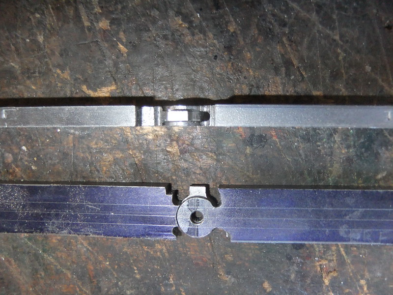 DSCF2605 DSCF2605 by Dalboy, on Flickr |
|
dalboy
E-xcellent poster
Posts: 235
|
Post by dalboy on Jun 26, 2022 20:03:58 GMT
Well progress took a step back over the last couple of days the coupling rods need to be drilled either end to fit the wheels but something just did not line up after a bit of checking and double checking found the quartering was out very slightly so removed a wheel on each set and then reassembled only to find the problem returned.
Checked my jig which I was using and all OK there eventually found out what it was for the last 1/8th inch the wheels twisted slightly as that had to be pushed out of the jig the fault was the G clamp I was using as I was tightening the last bit it caused the problem.
So assembled them up to the last 1/8th inch but this time used the metalworking vice and because there is no rotational forces like the G clamp they went on straight. Problem solved but it did take a couple of days.
Hopefully back to the coupling rods tomorrow as everything seems to all line up now.
|
|


