abby
Statesman

Posts: 925
|
Post by abby on Jan 17, 2023 23:05:09 GMT
Shame Greenglade has departed as gauge 1 doesn’t have many followers on this forum but I will attempt to add some of my own thoughts and findings for anyone who may be interested in the smaller gauge
I think that authentic looking wheels make a good model better but getting really good wheels
can be expensive.For my model I decided to produce my own wheels utilising investment casting.
However I hit a few snags , I don’t cast in iron , only in copper based alloys , so the wheel castings would have to be made from brass. 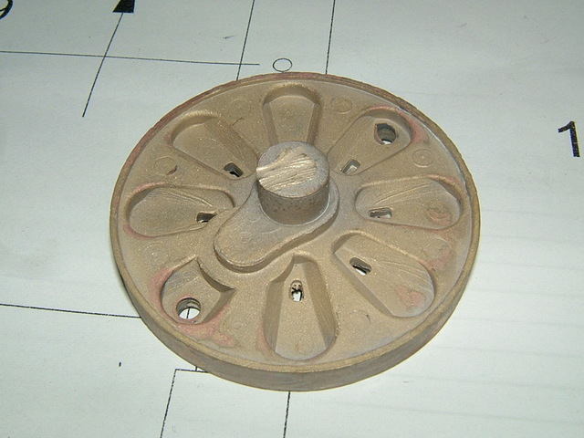 Well that’s ok because most of the wheel is painted , but the rims aren’t , and brass rims look pants , to use a Manchester adjective.So it had to be steel tyres fitted to the brass castings , but how to get the steel rims ?
A slice off a thick walled tube would work but anything near the size required was prohibitively expensive , I tried forging the rims from sheet metal which worked but was very labour intensive , in the end I contacted my local steel stockholder and asked for a quote for the rims laser cut from 6mm mild steel.
The quantity supplied for their minimum order charge was amazing and I got the smaller rims from the inside of the large rims ,
the cost was a few pence per piece. 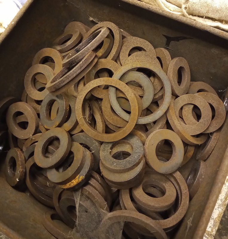 Machining the wheels is pretty straight forward as the lost wax castings are a very accurate starting point. The wax patterns are made by high pressure injection into a metal die , so size and concentricity
are reliably within a thou or two.This makes batch machining a doddle ,
the lathe can be set up for repeat operations making the facing back and front very quick. 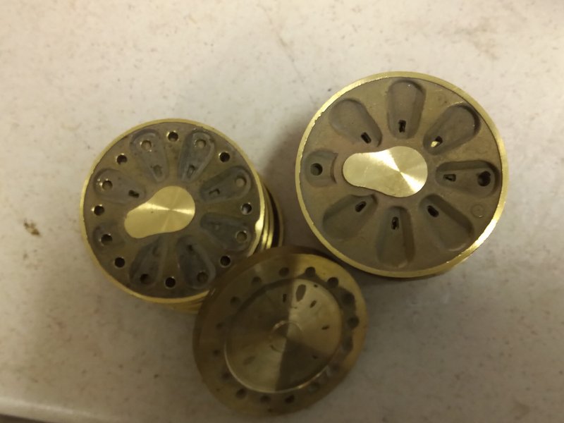 After facing the centres are drilled and reamed 7/32” for the axles and when the batch is complete the wheels are transferred to a faceplate on a 2 morse shank with a central 7/32 register and screw lock , the diameters are finished in this op. the machining of the rims is straight forward , I hold the blank in the 3 jaw whilst machining the bore to fit the machined castings. I have tried several methods for fixing the rims to the centres including soldering and heat shrinking but the most reliable appears to be Loctite , my Boxford”A” is capable of repeating the push fit required for a batch of 6 wheels. |
|
|
|
Post by noggin on Jan 19, 2023 8:26:05 GMT
I am watching this with great interest, I am building in gauge one, coming down from the larger scales.
|
|
abby
Statesman
Posts: 925
|
Post by abby on Feb 5, 2023 10:36:46 GMT
after fitting the rims they are machined to the required profile which can be found on the G1MRA website.
You can use 1/32 scale or 10mm depending on your chosen build scale , and some builders advocate making the depth of the rim 1/2 a millimetre deeper than standard to prevent de-railing at points and crossovers etc.
Finally the various holes through the wheel castings are cleaned of casting flash and drilled out before bead blasting and etch primer.
|
|
abby
Statesman
Posts: 925
|
Post by abby on Feb 5, 2023 13:33:48 GMT
Past experience has shown that brass wheels that are a pressed fit onto axles come loose quite quickly,and also, during the build I have found it necessary to remove the wheels from their axles several times.
A method of fixing the wheels firmly and correctly quartered yet being able to be quickly dis-assembled was required.
The obvious answer was a keyway, but finding a broach for a 7/32” hole was unsuccessful.
I have a 1/4” bore broach but this would mean using 9/32”, axles as a shoulder is needed for the wheels to butt up against and space apart correctly.
The increase in axle diameter causes changes through-out the design and sprockets,bearings,eccentrics and even the C/S head socket screw that finally tightens the wheels would all have to be changed, so something else was needed.
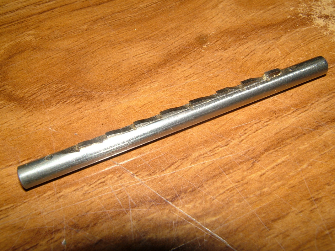
I tried making a smaller diameter broach by milling a 1/16” slot in a short length of 7/32” silver steel.
A slice of HSS cut from a broken slitting saw was soft soldered into the slot and the teeth filed with a diamond file.
The HSS was suprisingly easy to shape with the diamond file and made quite a passable job of the broach, even made me think that more complex items such as spline broaches could possibly be attempted by this method.
A keyway cut into the wheel hub would have to locate the wheel at it’s correct “quartering” as well as securing it.
For a two cylinder engine this is of course 90°,if the axle keyways are in line on the same side then if the wheel keyways are cut at 45° from a datum , when assembled the wheels will automatically be quartered at 90°.
As the obvious datum on the wheel is the crank pin locating hole a jig was needed to locate the hole position for drilling.
Because my aim is to build several identical models I spend a great deal of my model building time actually making jigs and fixtures and even tools and tools to make tools , but it’s all part of the fun.
|
|
abby
Statesman
Posts: 925
|
Post by abby on Feb 6, 2023 19:56:48 GMT
After some thought it was clear that a single jig would enable the crank pin hole drilling and broaching the wheels .
A steel blank about the diameter of the wheel was machined to leave a 1/2” diameter hub and then reamed 7/32”, when reversed the hub fits the centre hole of the rotary table.
A wheel blank placed onto the jig crank-web up,was centralised using a 7/32” locating pin.
then using the outer wheel holes (at 12 and 6 o’clock) for location two holes were drilled through the base of the jig.
With the blank re-positioned centrally on the rotary table hub upwards and the two drilled holes set at 0° on the x-axis the table was moved 7/16”(half the stroke) and a 1/8” hole for the crank pin location drilled and reamed.
Finally ,put back to starting point the table was rotated 45° and a 1/16” slot milled across the hub down to the body of the jig.
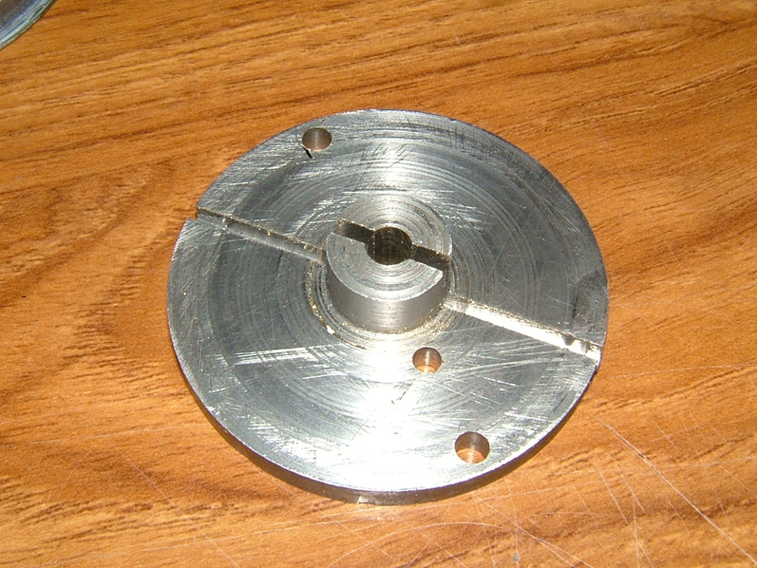
I hope that is a clear description of making the jig , using it was easier!
A wheel was located on the jig , web side down, using a central pin through the axle hole and pins through the outer two holes.
held thus the crank pin hole could be drilled in the wheels with repeatable precision.
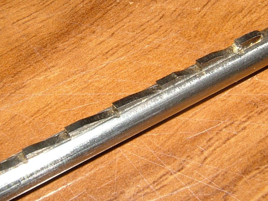
Broaching the keyway is also easy , the broach has a 1/16” hole through it which takes a short piece of silver steel
with the wheel in the jig located through it’s axle and crank pin holes , the broach could be placed into the hub using the 1/16” silver steel rod for radial positioning , pull out the rod and push the broach through.
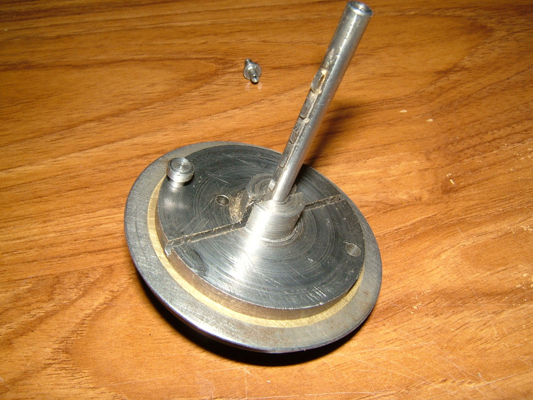
I used this set-up on my drill press and it cut a near perfect keyway , however when assembled on axles I found unacceptable discrepancies in the quartering which I believe due to slight rotation of the broach during pressing.
|
|
abby
Statesman
Posts: 925
|
Post by abby on Sept 4, 2023 13:01:33 GMT
It was quite a disappointment , several hours of effort proved useless , but if you learn something new then it isn’t wasted and hopefully there is something there that may help some other project.
It occurs to me that I never really explained why I don’t cast iron , it isn’t that I can’t melt it , but that the investment powders I use are gypsum based , this means the maximum temperature of the molten metal cannot exceed 1250°C or the cement can react exothermically and break down. I can just about cast nickel silver.
For high temperature melting alloys including platinum the investment cements are phosphate based , or ceramic shell which is a totally different kettle of fish.
Anyway back to my engine build , after thinking about the problem for a day or two I had the idea that if the wheels had a slot in the back and the axles had a pin through then this would work as well as the keyway and be easier to manufacture too.
|
|
abby
Statesman
Posts: 925
|
Post by abby on Sept 4, 2023 15:10:08 GMT
As usual a couple of jigs needed , one for drilling the axles for the 1.0 mm rods and one to hold the wheels whilst cutting the slot.
The first was easy , just a piece of square bar with the holes drilled thru' at the correct spacing, and exact axle length.
The axle rods ,cut roughly to length , pushed into the jig and the first hole drilled thru'.
With the axle rod held in place by a piece of 1.0 mm silver steel in the first hole the second hole can be drilled.
The axle still in the jig can now be transfered to the lathe (my Boxford has a s/c 4 jaw fitted most of the time) and each end faced to length.
The second jig needed a bit more work , it is basically a steel disc 4 3/4" diameter with a 1/2" spigot that allows it to be clamped centrally to the BCA table. The top side is machined to locate a wheel face down.
The wheel is located in the fixture using a pin thru' the crank pin hole and the knurled clamping screws tightened , after the initial set-up at 0° the table is rotated 45°. The slot is now milled using a 1.0 mm ball nosed cutter.
It only takes a couple of minutes to cut the slot , and a set of 6 wheels can be done in a quarter of an hour. The main thing is that over a run of 30 wheels they have repeatable accuracy and when mounted on the axles the quartering is perfect and the wheels run true.
this is my gauge 1 cupboard
Hoping to restart model building soon
|
|