|
|
Post by havoc on Jul 15, 2007 12:33:43 GMT
This is the preliminary intro to my new project. The plans aren't even halfway finished, but there is so much unknown that I started to cut some metal. And I will have to ask here sooo much questions I beter get started. After visiting a preservation group here in St-Ghislain (http://home.tiscali.nl/dollyscavia/ghislain.htm) I fell in love with this engine: 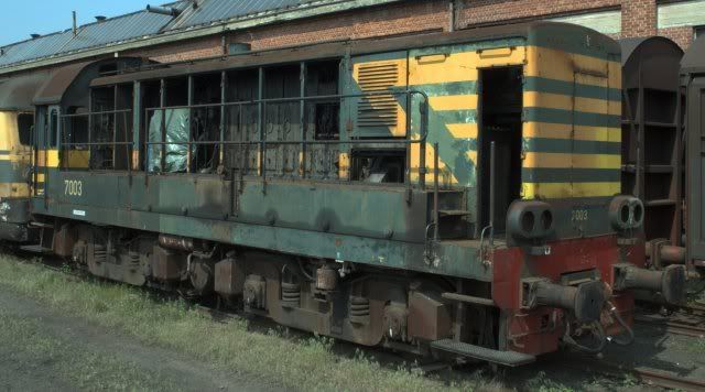 They have one less eaten by giant moths  (this is one for spare parts) Sadly it is a diesel-electric and as such not cosher in a live steam group. So I started playing with the idea to make it as a steam-electric. After messing around with several types of boilers, looking for a simple way to make a generator and trying to fit everything into the shape and size of the proto I ended up with the following: 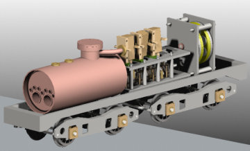 From this it looks as if everything will fit into the outline of the prototype. We'll see later if that is true... 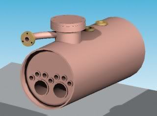 The boiler is based on a Scotch marine type. There will be 2 burner tubes with the butane burners at the front of the loco. The return chamber is towards the center of the loc and will house a superheater of the hairpin type. There won't be a real stack but I'll use the opening of the fan in the prototype as one. 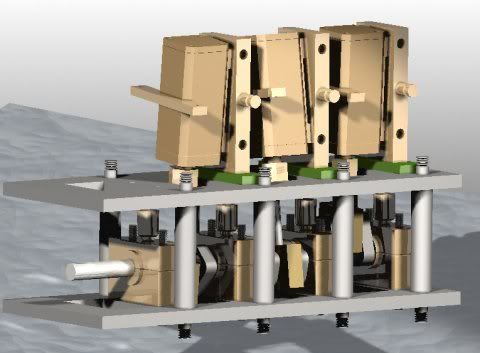 The engine is tought of being a 3-cilinder oscillating type. Bore 8mm, stroke 12mm. At the moment there is some space left for a possible water pump. But if that will be fitted depends on some unknown parameters. (is there space left for the pump and a tank?) 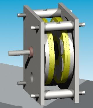 Then the alternator. This is a tri-phase radial flux type using NdFeB magnets. The magnets sit on the rotor while the coils are stationary. So no commutator, only some diodes to rectify. The alternator will also function as a flywheel for the moter. To be safe I added a gear ration between motor and alternator. All the rest is more or less in limbo  and will be made up as needed ;D The plan of action for the next years (?) is: - making the alternator and see if this can put out enough power to drive a loc! - making the steam engine and see if that can at a reasonable pressure turn the alternator - making the boiler and see if that can produce enough steam. Then I'll get on with the frame and bogies. I want it to be driven on all axles with a nose suspended motor. |
|
|
|
Post by havoc on Jul 15, 2007 13:03:59 GMT
The first cut is the deepest.... Started on the alternator. Diameter is 50mm, so a bar of 55 was just perfect to start with. Turned a part to diameter (+ a bit): 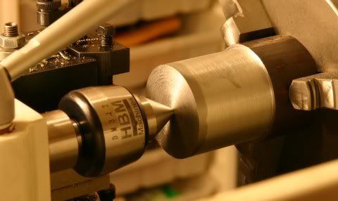 Next the half bobbin was turned. More swarf than final product. 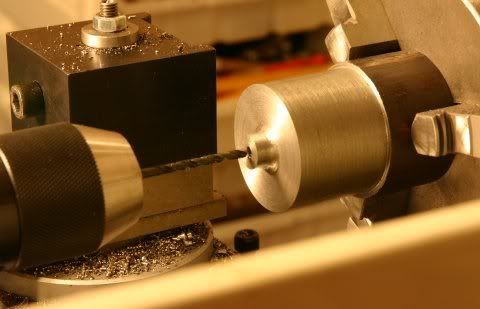 Then 2 flats on the small diameter of the bobbing so I could drill 2 holes for grub screws to keep the thing on the axle. 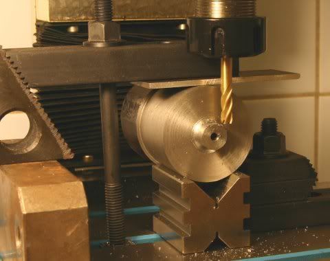 Setting this up proved to be harder than expected. I could not clamp the V-blocks directly to the table as the clamps I have are to large to fit the grooves. And using the bracket of the V-block didn't work either as it blocked the mill head. And then the clamp I put over the lot fouled the head as well. And then the mill needed to be extended as far as possible to reach the small boss. And all that for a simple flat so I could centerpop for drilling. I intend to keep this log up to date as far as possible. Also as a means to force myself to work on the loc and deliver decent work that can be shown. All remarks and comments are welcome of course. |
|
|
|
Post by baggo on Jul 15, 2007 15:36:32 GMT
Hi Havoc,
Looks a very interesting project. It's nice to see something a bit different. I for one look forward to following your progress.
John
|
|
abby
Statesman

Posts: 925
|
Post by abby on Jul 15, 2007 19:58:19 GMT
I will second that.
|
|
steam4ian
Elder Statesman
 One good turn deserves another
Posts: 2,069
|
Post by steam4ian on Jul 18, 2007 21:53:00 GMT
G'day Havoc.
What a great project! The alternator is fascinating but will it work? Why not use a dc motor as a generator?
I have considered a similar project for equally cheeky reasons, only 5" guage. The preservation society of which I am a member has an 0-6-0 diesel shunter that began life as a steam saddle tank loco. It was converted by the then Commonwealth Railways using an engine and transmission from a Gloucester Rail-car (DMU). Why not convert it back? A flash steam boiler would prevent me having to trouble the boiler inspector.
Keep the dream going.
Regards,
Ian
|
|
|
|
Post by havoc on Jul 19, 2007 10:09:54 GMT
Thanks for the interest. More will have to wait until after my vacation. (visiting some train related stuff is on the list)
No idea if it will work. That's the reason to start with it. It is a scaled down version of the type used in wind generation for diy green energy (or in the wilderness).
The reason a DC motor was ruled out is speed. A DC motor works most efficient at a speed near its designed rotation speed. But this is far higer than a steam motor can reach. So it would need gearing up. Then there is the question of it would still work as a fly-wheel. Looked also at stepper motors but they are bulky with respect to their power output.
Making it this way will also let me change the voltage output by changing the windings. This to get closer to the working voltage of the motors.
|
|
|
|
Post by Shawki Shlemon on Jul 22, 2007 10:12:09 GMT
Forgive my ignorance , has there ever been a full size steam electric , if not then this is original idea. Good on you and I am impressed and will follow the progress .
|
|
|
|
Post by havoc on Aug 4, 2007 19:36:50 GMT
Thou are forgiven. Yes, there have been steam-electro locs in 1:1. They were even more ambitious than this project. But they all came to the same conclusion: putting a whole electricity plant on wheels isn't a good idea. The coal got into the electric motors and the water in the electric circuits...both rather bad combinations. The first was the Heilmann in France: www.dself.dsl.pipex.com/MUSEUM/LOCOLOCO/heilmann/heilmann.htmThe others used turbines: www.dself.dsl.pipex.com/MUSEUM/LOCOLOCO/upturb/upturb.htmwww.dself.dsl.pipex.com/MUSEUM/LOCOLOCO/chesturb/chesturb.htmwww.dself.dsl.pipex.com/MUSEUM/LOCOLOCO/nwturbine/nflkturb.htmThere is a lot of other fun stuff on that site! So no, it isn't original, and afaik there is even a gauge1 steam-electric "in operation". The builder of that one and me got the idea at about the same time. But I was busy with other projects at that time. So he has already finished his. This is more along the lines of the Heillmann with some rather special features like a forced draft alcohol burner. He got about 60W out of his dynamo (conventional type with collector). But it is larger than what I want to build. EDIT: replaced the last link (as it was a duplicate) with a third example. |
|
|
|
Post by Shawki Shlemon on Aug 6, 2007 10:22:35 GMT
Thank you for that , very interesting sites . I will get back to those sites again and spend more time on them .
|
|
steam4ian
Elder Statesman
One good turn deserves another
Posts: 2,069
|
Post by steam4ian on Aug 6, 2007 21:36:05 GMT
G'day Havoc.
Can you or you friend please post some details and pictures of his loco?
I am particularly interested in the forced draft alocohol burner.
Regards,
Ian
|
|
|
|
Post by havoc on Aug 7, 2007 19:42:35 GMT
Easiest will be to visit his site: homepage.ntlworld.com/sheila.capella/cabbage/default.html Follow the link to "Heilmann"... The others are just as excentric! I met him at another forum and both are coming there less and less as it consists more of buyers than builders. I tried to get him over here but I didn't work yet. |
|
|
|
Post by havoc on Dec 29, 2007 16:47:12 GMT
Finally some work got done. Well, after learning a lot about making "flat bottom holes" I could tackle the alternator. First centering one of the locations of the magnets using a center in the mill arbor: 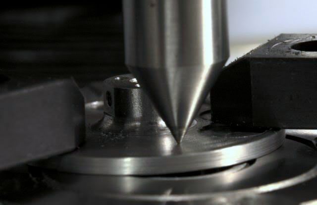 Then first milling the center away: 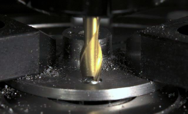 After 8 times one half is done, another half of the rotor to go: 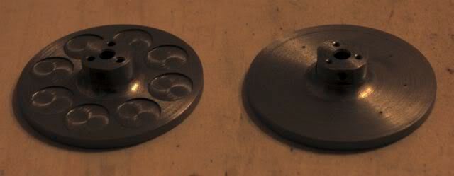 Both done, and the magnets put in place with some Loctite: 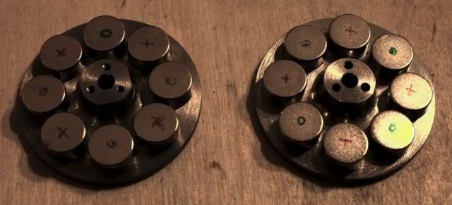 Both halves of the rotor mounted on the axle: 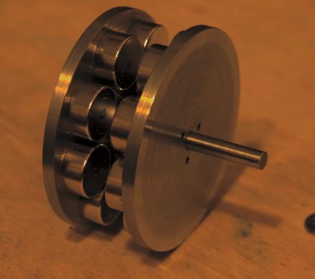 There are 3 M2 screws holding both halves together. But they are not really needed, the magnets alone keep everything verywell together. Tomorrow I'll paint some it in anti-rust so it is safe while the rest of the engine is made. The pictures aren't very good, but I'm working on a portable this time and an LCD isn't the same as a CRT. And using a different soft doesn't help either... |
|
abby
Statesman
Posts: 925
|
Post by abby on Dec 30, 2007 12:11:40 GMT
Good to see some progress on what should be a very interesting project.
|
|
|
|
Post by modeng2000 on Jan 4, 2008 7:47:53 GMT
|
|
|
|
Post by havoc on Jan 4, 2008 11:02:43 GMT
I have met Ralph on another forum. There we found out we had a similar idea at about the same time.
|
|
|
|
Post by havoc on Jan 4, 2008 22:34:29 GMT
Work on the frames is going on. Apart from the sudden problem with the magnetic shaft this is going reasonably well. Screwed 2 pieces of 3mm sheet steel together and milled 2 reference edges so I could mark out the holes to drill for the bearings, mounting holes etc. After I had done that I realised that i could just as well use the mill as a coordinate drill. So I kept the frame plates on the table and located each hole, center drilled and drilled. 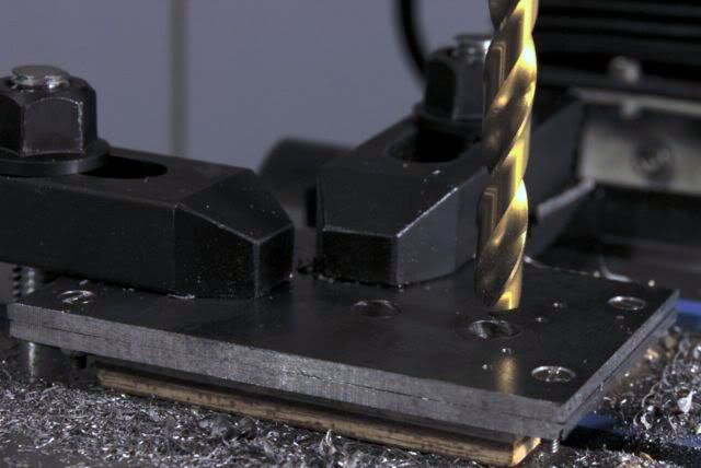 Afterwards I just milled it to size without the frames ever leaving the table. These are both frames. Large holes are for the bearings. Those present are the bearings for the alternator itself. Of the other 2 large holes, only one will be used for a bearing for the driving shaft. The bottom row holes is tapped M2 to mount the alternator to the motor base. The four 4mm holes are for bolting both frames together and keeping them in line. Holes are reamed for this. 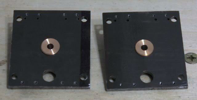 The top (double) row of holes is to fix other "stuff". At least some oiler cups for the bearings will come there. Depending on how the electronics will end it could be used to fix pcb's or so. Only the topmost row will be used. The other row is an error, but I couldn't bring myself to start again because I had drilled some less important holes at the wrong place. I'll solder some stub in it, file flat and paint over it  |
|
paul
Member

Posts: 8
|
Post by paul on Jan 28, 2008 21:51:20 GMT
Any progress Havoc? Three weeks since the last post!
|
|
|
|
Post by havoc on Jan 29, 2008 11:06:10 GMT
Not much I'm afraid. Family with a broken leg and I need to help out there, spend best part of a week in bed (and on the p*t) myself. (and I got sidetracked with that stripped gear) But I started on a few small parts like oilcups while I finish the drawings of the engine frame. The only thing that bothers me there is "do I fit in a water pump or not?" This will make a difference of a few cm that I could use for the boiler  I'll put up a few pics this evening to keep you quiet... |
|
|
|
Post by havoc on Jan 29, 2008 20:51:18 GMT
Ok, as promised oil cup. You take a piece of brass rod and stick it in the lathe and turn it to external diameter: 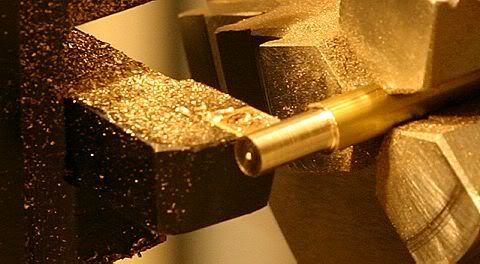 Then you center drill: 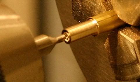 Drill to size: 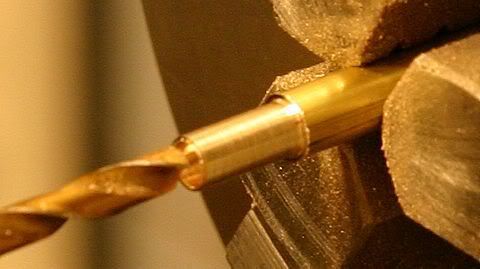 Then with a parting tool cut the piece where the thread will come: 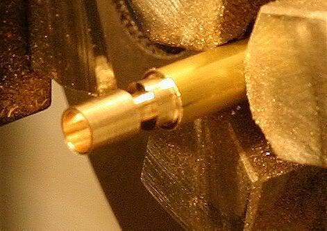 Go for it a few times and then part it. Don't loose it in the scrap... Rinse and repeat: 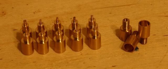 The 3 ones on the right are finished and will be used for the bearings on the alternator. This was reasonably rough and ready work. I didn't work to the last 0.05mm. This was done on a chines lathe, with chinese bits and drills ;D I have no idea where the brass came from other then from the nearest DIY. Edit: I made the spacers for the frame of the alternator. But I don't have a pic of the alternator assembled. And I disassembled it already. That's for next time. |
|
paul
Member
Posts: 8
|
Post by paul on Jan 30, 2008 15:44:49 GMT
This is what I like to see, practical stuff!
|
|
 (this is one for spare parts)
 and will be made up as needed ;D


