|
|
Post by jamesb on Feb 2, 2008 17:38:42 GMT
This is immensely interesting, I shall certainly be looking forward to the next installment. Out of interest, browsing through Model Engineer today there is an article about a model electro steam, I didn't get to read it properly as I forgot my wallet.
|
|
|
|
Post by havoc on Feb 2, 2008 18:43:00 GMT
Thanks for letting me know about that. I'll see if I can get ME somewhere around.
|
|
|
|
Post by ralphbrades on Mar 9, 2008 9:01:25 GMT
OK Havoc,
I give in! The reason I have not posted here is because of embarrassment. I don't have a Lathe or Milling machine -just a pillar drill and piece of work surface by the kitchen sink... Having examined the information here -yours is going to be a work of art compared to mine!!!
regards
ralph
|
|
|
|
Post by alanstepney on Mar 9, 2008 9:26:31 GMT
Ralph,
Dont despair. Or get embarrassed.
Look through earlier Model Engineers, and you will find plenty of models that were built without machinery. Often using what you have or even less.
OK, they may not be to the standards that would win awards, but if someone ends up with a working model made using minimal equipment, that is a major achievement, of which they should be proud.
|
|
|
|
Post by havoc on Mar 9, 2008 9:53:17 GMT
Hello Ralph, nice to meet you here as well. You make it all up with originality. There are not much others here having made forced draft burners or Klose links. (actually none that I know of) I don't think it will be a piece of art  But the progress (or lack of it) is slowly bothering me. So far I have more misdrilled holes than others. And my first attempt at milling isn't very good either. Maybe I'll add a few pics this afternoon. I have to re-install windoze on a friends pc and that will give me something to do while waiting for "press any key to continue"... |
|
steam4ian
Elder Statesman
 One good turn deserves another
Posts: 2,069
|
Post by steam4ian on Mar 9, 2008 10:45:59 GMT
G'day Ralph Here is a link to a project that can be made without lathe etc. blog.modernmechanix.com/2006/11/16/fizz-whizza-midget-steam-car/I am starting to look at "machine free" projects to demonstrate at club open days just to wet peoples' appetites. "I could/can do that." The trouble is that as I become more tooled up I find it more difficult to step backwards.  Good to hear from you. Sorry for hijacking the topic Havoc. Regards, Ian |
|
|
|
Post by havoc on Mar 9, 2008 11:05:20 GMT
|
|
|
|
Post by havoc on Mar 9, 2008 18:08:58 GMT
Some pics of the slight progress so far. The alternator is about ready. Only the bearings have to be soldered in place. But that is for when the frame is ready so I know it can be lined out with the motor. Also needed are 2 brackets to bolt it to the frame and 2 brackets to hold the oil cups for the bearings. 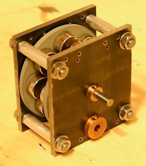 But the work on the frame started. First time I did some milling. Started with bolting the top and bottom frame together and put in 2 reference edges. 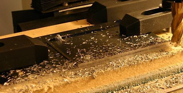 Then the holes for bolting top and bottom together were drilled in 1 go and the 3 square holes where the crank will pass through the bottom frame and the connection rod through the top frame. The 4th hole in the bottom frame is for an eccentric to drive a feed pump. Then a 2 rows of 5 holes to bolt the alternator at the left. After top and bottom were split the holes for mounting the crankshaft bearings were drilled. Bottom frame: 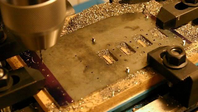 Top frame: 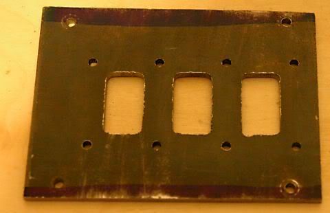 Next will be bringing the bottom frame to size and then drill the mounting holes for the cylinders and bring the top frame to size. |
|
paul
Member

Posts: 8
|
Post by paul on Mar 12, 2008 22:12:40 GMT
Looking good Havoc (and sounds complicated!)
Ralph, I made my first two engines with hand tools only. It's hard work but it can be done and is very satisfying as Alan says.
|
|
|
|
Post by ralphbrades on Mar 15, 2008 13:01:10 GMT
Thank you everyone for your encouragement in the engineering bits!!!
The main problem I have discovered is the matching of the generation side to the traction side. Havoc is using the alternator design from the "Institute of Intermeadiate Technology" whilst I am using a self energising dynamo design from 1910. Both of these designs are intended to re-charge Lead Acid Storage cells. I am thinking of re-building several parts to improve performance. Although the Heilmann works I would like something more than 15cm per second ;D
regards
ralph
|
|
|
|
Post by havoc on Apr 6, 2008 13:14:36 GMT
At last I got to spend some time in the shop. The frames for the engine have been drilled and tapped. small hitch during tapping: a tap broke and didn't want to be removed. So I sawed out a piece around it and soldered in a new piece. 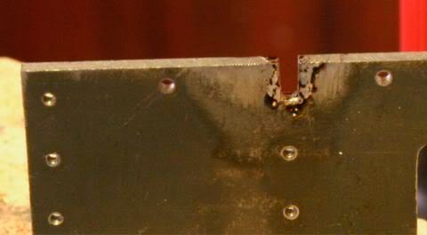 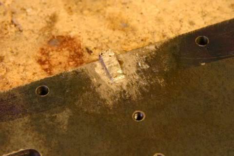 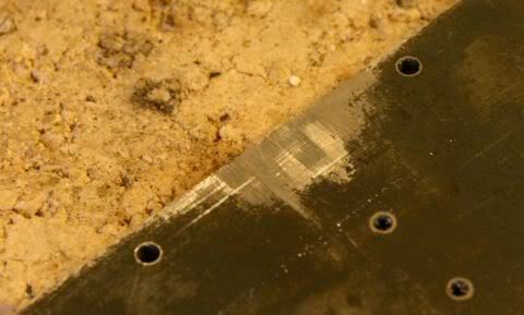 It won't get hot and there are screws enough so the stress won't be large enough to pull it out. Some material arrived so work on other parts of the engine could start. The engine will be a 3-cylinder oscillator. First the portblocks were tackled. First try of the port blocks on the their frame. 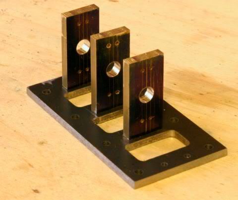 The base of the post blocks is now finished. And here they are on the engine frame. 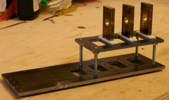 A piece of insulation sits between each port block and the frame. At the moment it is still some styrene, this will change whenever I get my hand on it. Next step will be to solder in bronze pieces for the cylinder bearings and the posts for the springs to keep the cylinders on the blocks. And the standoffs between both frames need to be made as well. Still plenty of work to do. |
|
|
|
Post by havoc on May 12, 2008 18:17:54 GMT
A quick update. So far the spacers and the angle brackets for the alternator have been added to the motor frame: 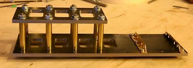 Still a bit work at the angle brackets. And a little fault was discovered: the screws in the alternator and those in the frame are in each other's way. But there are enough of them so leaving a few out won't matter  On to the crankshaft bearings. I wanted to make split bearings with a bronze insert in a brass block. So I started with brazing a piece of bronze in the brass block: 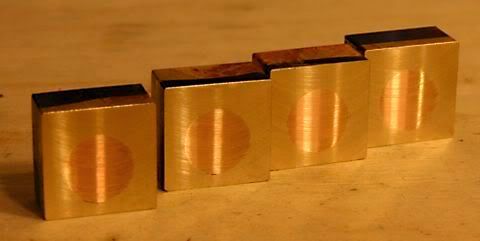 Then slitting the blocks in 2: 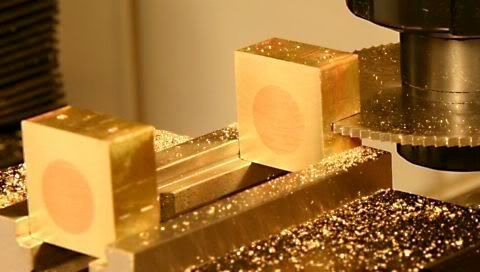 After making everything to size and drilling/threading a hole for the oiler cups they looked like this: 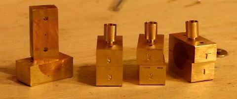 I made the mounting studs and soldered them into the lower part of the bearing block to check the dimensions. All in all it looks like this now: 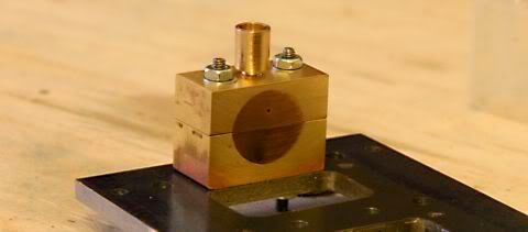 Only the first bearing is finished this way. But I had enough of it for so I stopped while the going was good. I found that the sequence of work wasn't good. But too late, I can only compensate now. To Sir Circlip: it would have been a lot better to go with split block with a separate bronze piece. |
|
|
|
Post by havoc on Jun 16, 2008 20:41:48 GMT
As told in another thread, the bearings in the previous photo were ruined beyond salvation. So I had to start again. This time I'm making split bearings consisting of a brass block to hold bronze bearing pieces. The making of the blocks was similar to the previous steps so I took no new pictures. The hole for the bearings is larger of course. 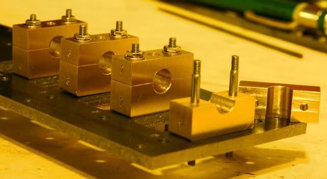 Remark: don't call your file a bushing as photobucket doesn't like that. Calling it a bearing is OK with them. |
|
paul
Member
Posts: 8
|
Post by paul on Jun 17, 2008 21:18:35 GMT
Why brass blocks Havoc, surely steel would do and save you $$$'s?
|
|
|
|
Post by havoc on Jun 18, 2008 6:44:13 GMT
Because I have brass around and no steel of that size. And I can only by it in 6m lenghts...
|
|
|
|
Post by havoc on Jul 14, 2008 10:10:31 GMT
I tought I had posted an update yesterday, but nothing is here. So I'll try again. I got some new bronze, RG7 a leaded bronze for bearings. The first try was to make the bushings as separate ones like this: 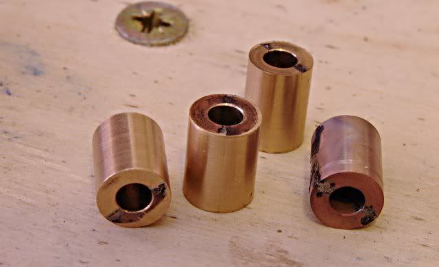 Took some time to get there, but when I was there after a few evenings I found out I couldn't turn these pieces to the required bobbin shape  Just no way to get some grip on them. So I started again with a larger piece of bronze 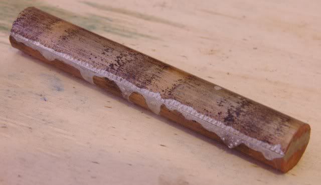 Then drilled the holes and turned to bobbin shape 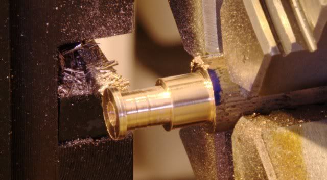 Once I got the photo taken I found out this wasn't the way to proceed as the piece broke off the stick and flew through the shop.  But I was prepared and the stick was long enough to get 4 bearing out it even after wasting one. Then drilled through the block and bushing in one go and put a pin in the underside of the block. The hole at the top will serve for lubrication. 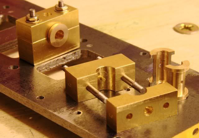 Last step will be to ream them through. |
|
brozier
Part of the e-furniture

Posts: 335
|
Post by brozier on Jul 14, 2008 20:59:12 GMT
Hi Havoc, Great work, it's nice to see your pics I've found when making delicate parts that it works best to turn the outside first so you have the strength of a solid core to press against. Then drill and bore the hole just before parting off. That way the forces are into the chuck where the strength is I've managed to turn some wafer thin parts using this method.... Cheers Bryan |
|
ace
Statesman
Posts: 528
|
Post by ace on Jul 14, 2008 21:39:57 GMT
Excellent work Havoc
Like the clear close up pics what camera do you use.
ace
|
|
|
|
Post by havoc on Jul 15, 2008 10:11:47 GMT
So did I this time  Once you found out it is a "Doh" moment, why didn't you tought before of that. But I don't think I'll forget it this way. Photo's were taken with a Canon 300D with a Sigma 17-70 2.8/4.5 Macro. Not the best equipment around, but using a tripod, using iso 100, aperture at 16 and self timer it is acceptable. The lens isn't a "real" macro, but it does allow close focussing and is good enough macro for this kind of parts. Even then it are crops to remove everything not wanted or relevant and then scaled to the largest dimention of 640 pixels followed sometimes by slight sharpening. I do have some problems getting whitebalance correct so while all the pics are taken with the same light on the same table the table changes color from light pink to dark straw. |
|
|
|
Post by havoc on Nov 4, 2008 21:11:22 GMT
Not much has happened lately but I'm at a turning point now so an update is due. The bearings are now soldered in the alternator frames, there are new angle brackets to hold the alternator, the bearings of the motor are aligned, the gears have arrived and the pieces to make the cranks are ready. 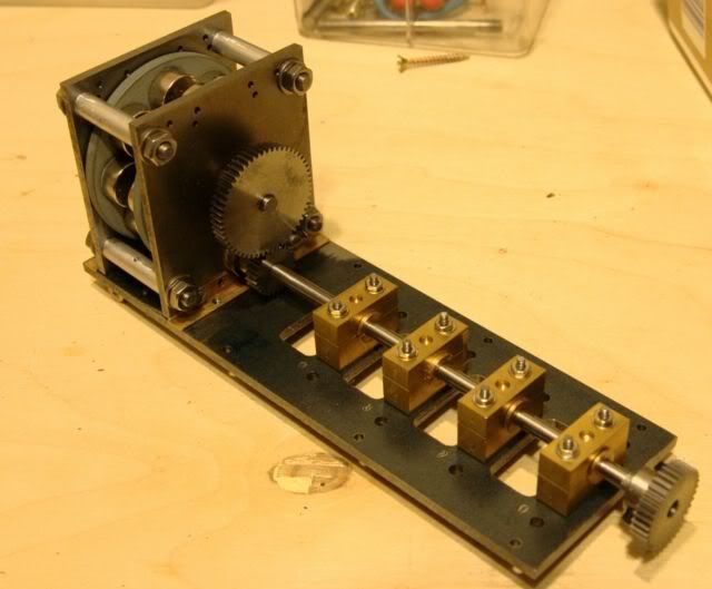 Result:the conclusion is that this will never work! The idea of ending the cranckshaft in a bearing in the alternator frames is a disaster. Lining it up once is feasible. But as there will be some work to do on that alternator this isn't an option. And then there is the problem to hold the stator. And the rotor itself turns against the bearings in the frames. This is a painted surface on bronze. So I decided to take the saw to it... 1: I'm going to put the alternator on a separate baseplate. This will allow for putting an universal coupling between motor and alternator making tweaking the alternator and alignment easier. 2: the pieces holding the frame of the alternator together will change and be in 2 pieces so it can hold the stator as well. |
|


 But the progress (or lack of it) is slowly bothering me. So far I have more misdrilled holes than others. And my first attempt at milling isn't very good either. Maybe I'll add a few pics this afternoon. I have to re-install windoze on a friends pc and that will give me something to do while waiting for "press any key to continue"...

 Just no way to get some grip on them.
 But I was prepared and the stick was long enough to get 4 bearing out it even after wasting one.


 Once you found out it is a "Doh" moment, why didn't you tought before of that. But I don't think I'll forget it this way.