ianmac
Part of the e-furniture

Posts: 308
|
Post by ianmac on Nov 5, 2008 2:06:35 GMT
Looks really good though, ive been following this and have eagerly been waiting for the next installment
Get a wriggle on! ;D
|
|
|
|
Post by havoc on Nov 5, 2008 10:59:37 GMT
Iw ill, just PM me any spare time you can miss ;D
|
|
ianmac
Part of the e-furniture
Posts: 308
|
Post by ianmac on Nov 5, 2008 22:28:24 GMT
HA! don't hold your breath! ;D
|
|
|
|
Post by havoc on Nov 15, 2008 15:24:15 GMT
Thanks to all the time PM'ed there is some progress. I shortened the frame and made the insulators between port blocks and frame. Also got the scale off (dirty job) and fitted everything back together. Doesn't look too bad. This is from the end where the water pump will come. Some day... 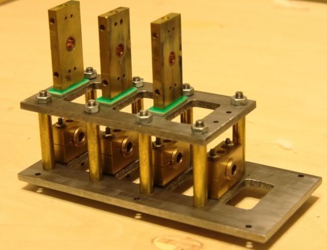 Started assembling the crankshaft. I'm using loctite but will pin it later on as well. 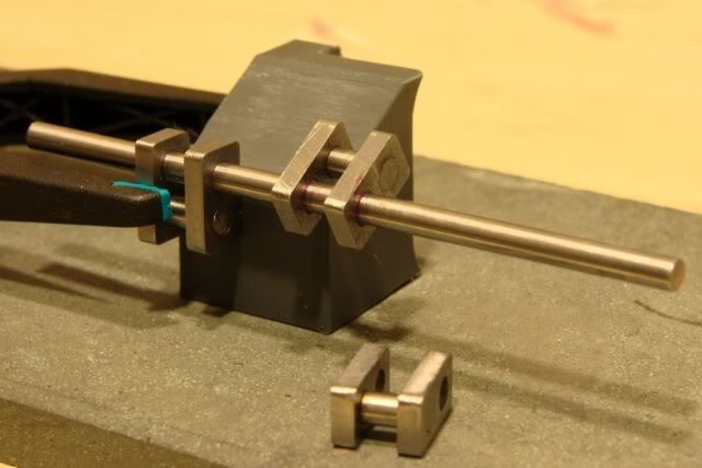 |
|
ianmac
Part of the e-furniture
Posts: 308
|
Post by ianmac on Nov 16, 2008 21:11:23 GMT
;D Really need to watch how much time im giving away!
Looks good!, i was always put off building a shay because of the cranks and those gears but it really doesn't look that difficult.
Im sure you will tell me otherwise though!. ;D
Looking good, keep up the good work!
|
|
|
|
Post by havoc on Nov 16, 2008 21:56:57 GMT
I depends on how fussy you are. This is really roughshod ME at its worst. I gave up designing in 3D and making plans of parts I cannot make. So I just start, adapt as needed and "design" in as much play as possible so that even worst case it still fits. Don't know if it will work. Everything is fit together with Loctite now. Going to try it out in the bearings tomorrow evening.
I just hope that once I start the 5" engine I'll find the courage to continue this one.
|
|
ianmac
Part of the e-furniture
Posts: 308
|
Post by ianmac on Nov 17, 2008 0:45:37 GMT
I am hoping that it will be asier to build the 5" loco.
The little fella is so fiddly, i do have castings for another G1 loco but i might give it a miss until my son is older and wants to build something.
Then we can do it together
Ian
|
|
|
|
Post by havoc on Dec 17, 2008 21:00:55 GMT
It was too cold to work so I emptied the CF in the camera and might as well post a few pics. That crackshaft of last post fits between the bearings. 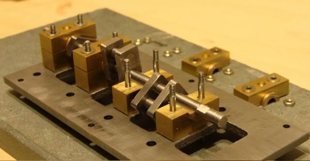 Started on the cilinders. 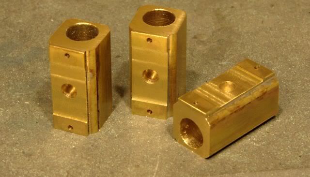 Now I'll have to drill and tap the holes to screw the ends on. But I haven't quite figured out how to set that up. |
|
ianmac
Part of the e-furniture
Posts: 308
|
Post by ianmac on Dec 18, 2008 2:59:03 GMT
they oscilating cylinders!
Very nice
|
|
|
|
Post by havoc on Mar 14, 2010 20:52:36 GMT
It has been a very long time since the last post here in this project but it isn't dead. Merely on suspended animation or something. I got sidetracked by this bad boy for a year. Tought it would take a month or 3 at most to move, clean and repair it: 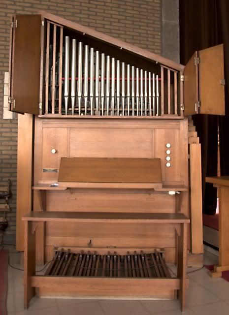 15 Months later it is rebuild in the spare room and I'm done with it, the rest is for a professional (tuning!). Back to this project: the cilinders where almost ready but also needed were: pistons, con rods, bearings, covers, etc. I didn't take as much photo's as before so you'll have to be happy with an overview: 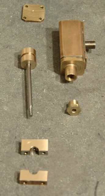 Pistons and split bearing were turned from bronze, con rod is silver steel the rest is brass. Right away some trouble popped up. It isn't a good idea to turn your cilinders excentrically out of a piece of square bar and try to do the same for the covers 1 year later...it doesn't fit. Well it does fit but it doesn't look well. After drilling and tapping the holes for the top cover I got bored with it and soldered the bottom cover (with the con rod gland) on. Another not so smart move. The bearing is tapped for the con rod so the length can be adapted a bit. I'll come back later to that... So I mounted the complete engine: 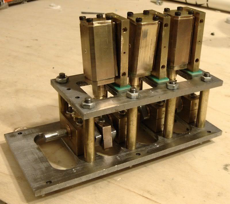 After the first fit together there were a few snags. The bearings fouled the frame so this was milled out with semi-circular openings. Then it turned out there is a problem at the bottom dead point. There is something that doesn't turn very well. It is hard to get over bottom dead point and the cilinders there moves away from the block. While trying to figure out what is wrong I found out that this motor isn't easy to work on. I think it is the piston hitting the bottom but because I soldered on the bottom covers there is no easy way to check. I cannot take a cilinder out of it without taking the ones in front out first. And I cannot loosen the cilinder block without first taking off the top frame. But then I need to take apart all the con rod bearings. etcetc And then there is the problem of connecting the steam pipes... So take a look at it, this piece is going into the scrap.  Making it work would probably take more time than building a new engine. Still I learned a good deal making it. Okay, searching the web for another engine I found this one: membres.multimania.fr/vapeurlanguedoc/plan7.htmIt looks like a small Stuart Sirius. Not only does it look simpler than the 3-cilinder oscillator it also has a slightly larger swept volume, less parts, less sealing surfaces etc. And the Sirius was used to drive generator sets, it is a fast runner. Not self starting however. I have drawn the plans in 3D again, changing a few parts a bit to be able to use material I had at hand. Also I choose to use the variant with a cilinder block brazed from parts. Used 3mm plate instead of 2mm and it is 25mm wide instead of 23. But that doesn't matter. Started this weekend and so far these pieces materialised: 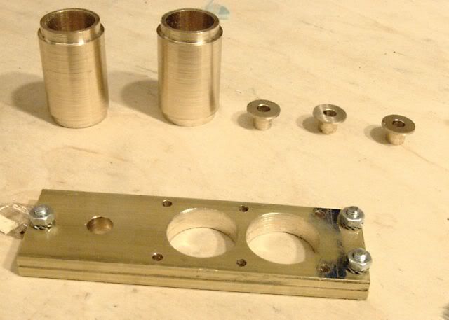 Both cilinders were made but they still have to be bored to size after brazing and the 3 bearings for the distribution. I added flanges instead of the little tubes in the original so they are easier to locate during soldering. And got to use the boring head for the mill the first time to make the holes for the cilinders. It looks as if it is going to fit together: 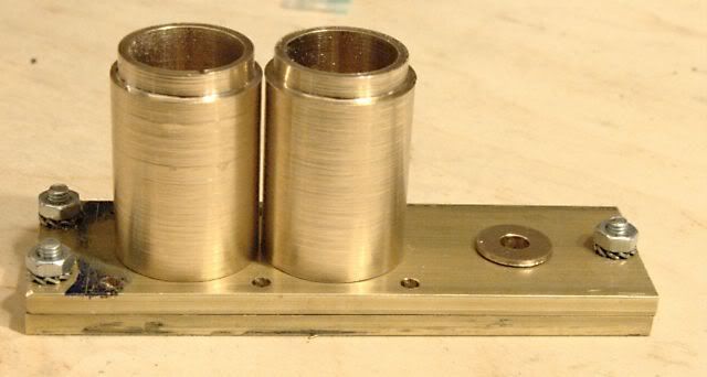 The gears for the distribution arrived friday so that's covered. I'll have to make the steam chest this week so I can braze everything together next weekend. Hope I don't have to scrap this one  |
|
|
|
Post by havoc on Mar 28, 2010 14:25:43 GMT
Bit of progress. Silver soldered the cilinderblock together. It would make a fair chance to win the "worst brazing job of the year" trophy. The bottom plate isn't flowed through completely but it is strong enough. Also soft soldered in the bearings and skimmed top and bottom plates. 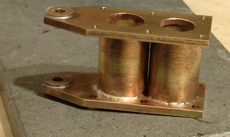 Then tackled the cilinderhead block. This is also silver soldered together and went much better. Quite a lot of holes in it. I changed a bit here from the plan. The original has banjo connections for the steam on top. But then it would be a fair bit higher than I wanted it to be. So I put the connections at the side. I'm waiting to plug the holes on top until the valve has been set up (might make that screwed plugs). 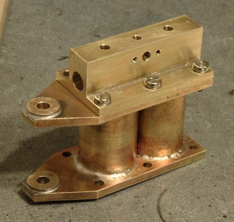 Next will be boring the cilinders to size. |
|
|
|
Post by havoc on May 19, 2010 20:06:31 GMT
A few parts added: 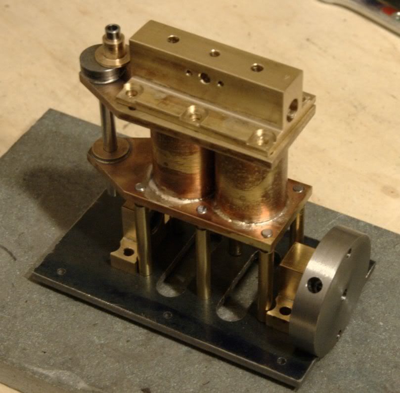 Some deviations from plan as usual. Made the bearings with small needle bearings. Not sure that was a good move, they feel "loose" around the axle. Then made the driving crank for the distribution. Just drilled out the piece of axle so I have an oilcup for those bearings. And added a flywheel. Don't get it why there isn't any on the plan. I feel that a 2-cilinder single acting needs a flywheel. |
|
ace
Statesman
Posts: 528
|
Post by ace on May 19, 2010 21:36:27 GMT
What a coincidence Havoc, I decided last week to make a start on my steam boat and dug out the same plans as your engine. ;D I will post some pics tomorrow, not got as far you though. I have the cylinder block machined out and the valve housing milled out too. I have just finished the banjos and bolts and I am now searching for a supplier for the bevel gears.
ace
|
|
|
|
Post by havoc on May 20, 2010 8:02:19 GMT
Ace, there is something fishy about the distribution of those plans (if you are using exactly the same ones). I can't get the finger on it where it is but if I draw this in CAD the the events are not symmetric for both cilinders.
Got the bevel gears from RS (521-5780). There are two problems. First it is easy to find bevel gears with 4mm holes or with 5mm holes, but not to find identical gears with 4mm and 5mm holes. And that plan uses a 5mm crankaxle and a 4mm axle for the distribution (I changed the crank to 4mm). Secondly the RS gears do not have holes for grub screws. Another option might be Conrad or Lemo-solar.
|
|
ace
Statesman
Posts: 528
|
Post by ace on May 25, 2010 22:28:05 GMT
Hi HAVOC Mine now looks like this, just about to star work on the crank shaft.  ace |
|
|
|
Post by havoc on May 26, 2010 10:12:41 GMT
So you're now further than I am. I started the pistons but after visiting an open day my enthousiasm has taken a nose dive...feeling incompetent, lousy and other superlatives. See you after summer (or something like that).
|
|
ace
Statesman
Posts: 528
|
Post by ace on May 31, 2010 20:09:48 GMT
Hi Havoc Sorry to hear that, I have just finished the bearing blocks but I won't hi-jack your thread any more but will start a new one for mine in the stationary engines section should you wish to see how I'm doing.  ace |
|


 Making it work would probably take more time than building a new engine. Still I learned a good deal making it.
