|
|
Post by syncopator on Feb 22, 2010 22:40:45 GMT
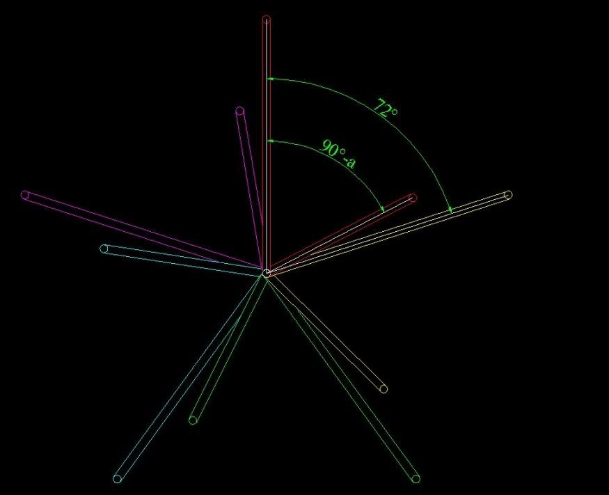
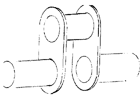
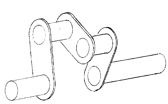
I want to put together the 5 cylinder stirling engine, all details of which may be seen via the top link at docs.google.com/Doc?id=dgdc4nmj_7d4373k&hl=enThe article's author used 2mm dia silver steel welding bar bent as shown below.  The connecting rod pair positions in the next picture are colour coded to relate to their respective crank journal pairs' angles, which are shown in the two pictures which follow.    The cranskaft is supported as shown in the next picture.  To make so many bends in the rod with any accuracy, especially for the alignment of the main journal's sections, would be a nightmare. Quite frankly I haven't a clue how to achieve it. I thought it might be easier to get more accuracy by bulding the whole think up, using separate lengths of rod and pieces of sheet as webs. Like this.  Or like this, using only three webs per pair of rods.  It would surely be easier like this to get the displacement angles right as well as good alignment of the main journal axes. Comments and observations please, |
|
|
|
Post by syncopator on Feb 22, 2010 22:43:05 GMT
Hmmm, but how would I mount the rods and support struts? The original had them all them all slid on to the bent rod.
|
|
|
|
Post by arch1947 on Feb 22, 2010 23:32:30 GMT
G'Day, I agree, getting a piece of thin rod bent accurately would be a nightmare. What you propose should work but the main journals would need to be supported in split bearings. No big deal just more work.
Good luck
Arch
|
|
|
|
Post by syncopator on Feb 23, 2010 1:52:55 GMT
Ok Arch, thank you. How might I implement split bearings? (My background is electronics, not mechanics.)
|
|
|
|
Post by drjohn on Feb 23, 2010 2:25:05 GMT
OK syncopator, since no-one else has offered any helpful suggestions, here's a medical answer - like you, I have little engineering background - self taught.
Get a shaft the right length and diameter, make the webs and cranks, slide them all into position and loctite them into place, then cut out the redundant bits of the original shaft. I've made cranks that way, and it works well - piece of cake! ;D
DJ
You could also slide the bearings on at the same time to save making split journals ! Lol - lazy ways!
|
|
|
|
Post by Paul Boscott on Feb 23, 2010 7:24:29 GMT
To make the wire option
Make it flat to start with draw the shape 1: 1 on your cad system glue the print out to a board put nails in at the corners bend the wire to shape. Make a paper protractor for the relative angles then using toolmakers clamps twist the cranks to the correct angles.
Paul
|
|
|
|
Post by Tel on Feb 23, 2010 9:40:35 GMT
My brain hurts
|
|
|
|
Post by drjohn on Feb 23, 2010 11:19:34 GMT
So THAT's what supports the pith helmet - I thought it was your hair. ;D |
|
|
|
Post by havoc on Feb 23, 2010 11:35:34 GMT
How accurate does it have to be? The advantage of the wire solution is that you can adjust later on. Almost impossible with the buildup version.
And the buildup version isn't that much easier to make accurate without a few jigs but then the same could be used for the wire version.
Probably the buildup version will need thicker wire (rod?) and plate than can be achieved with the bend wire version. Maybe also to consider. I get the impression this is for some kind of multi cilinder low temperature diff stirling and those aren't powerful.
|
|
isc
Statesman
 
Posts: 708
|
Post by isc on Feb 23, 2010 11:45:39 GMT
I agree with the method of making it flat to start with, then setting the angles by twisting the wire. What you have is 5 individual engines linked to gether,the important angles are the ones between displacer and power cylinder.The crankshaft could be made up as 5 seperate pieces linked together with a little tubewith grub screws which would allow for easy adjustment of individual units.I would suggest that a bits of 2mm bore plastic tube about2-3mm long be put on the cranks each side of the conrods to keep them central .isc
|
|
|
|
Post by syncopator on Feb 23, 2010 18:56:52 GMT
Get a shaft the right length and diameter, make the webs and cranks, slide them all into position and loctite them into place, then cut out the redundant bits of the original shaft. I've made cranks that way, and it works well - piece of cake! ;D DJ You could also slide the bearings on at the same time to save making split journals ! Lol - lazy ways! Great idea DJ, thank you. To make the wire option Make it flat to start with draw the shape 1: 1 on your cad system glue the print out to a board put nails in at the corners bend the wire to shape. Make a paper protractor for the relative angles then using toolmakers clamps twist the cranks to the correct angles. Paul Another good idea. I remember now, doing a simple version of this many years ago when I wanted to produce a few identical items from piano wire. I had forgotten about it! How accurate does it have to be? The advantage of the wire solution is that you can adjust later on. Almost impossible with the buildup version. And the buildup version isn't that much easier to make accurate without a few jigs but then the same could be used for the wire version. Probably the buildup version will need thicker wire (rod?) and plate than can be achieved with the bend wire version. Maybe also to consider. I get the impression this is for some kind of multi cilinder low temperature diff stirling and those aren't powerful. Thanks for your observations Havoc. It's a multi cylinder Stirling, yes, but not a low temp diff one. Take a look at the article in the link. The most critical figure to achieve is a 90 degree lead/lag between each displacer and its power cylinder, which is bedevilled in this design by the angled mounting of the power cylinders so that the angular difference between the displacer and power journals is less than 90, by the angle "a" in the timing diagrams. I shall measure this difference before final assembly of the crankshaft. The throw of each crank is not exactly critical but care needs to be taken to ensure that the displacer doesn't touch either bottom or top of the cylinder. I agree with the method of making it flat to start with, then setting the angles by twisting the wire. What you have is 5 individual engines linked to gether,the important angles are the ones between displacer and power cylinder.The crankshaft could be made up as 5 seperate pieces linked together with a little tubewith grub screws which would allow for easy adjustment of individual units.I would suggest that a bits of 2mm bore plastic tube about2-3mm long be put on the cranks each side of the conrods to keep them central .isc Another great idea isc. Thanks to all of you. I have several things to think of now. I think I favour the made up option rather than the bent wire one, for aesthetic reasons. A "properly made" crank would look more impressive. |
|