|
|
Post by Jim on Apr 18, 2015 3:03:05 GMT
Just a quick update to show not a lot of progress for a great deal of fiddling. An access panel has been added in the cleading behind the water gauges to allow the cleading to be removed without having to disturb the gauges. The water gauges are now in place along with the collars indicating the minimum water level. I should add the bushes for the gauges needed to be gently aligned before any permanent fitting of the glasses could be made. The other job completed has been the pipe work for the blower valve and pressure gauge. Yet to come, I have to complete the links to the fire door opening mechanism and make the cluster of three gauges on the driver's side which will if things go as planned, also help hide the blower connection on the backhead. Because I've run out of soothing ales I've now been reduced to sitting on a stool gazing at all this while making chuffing noises and opening the fire box door, one works at present.  Sad I know. Jim 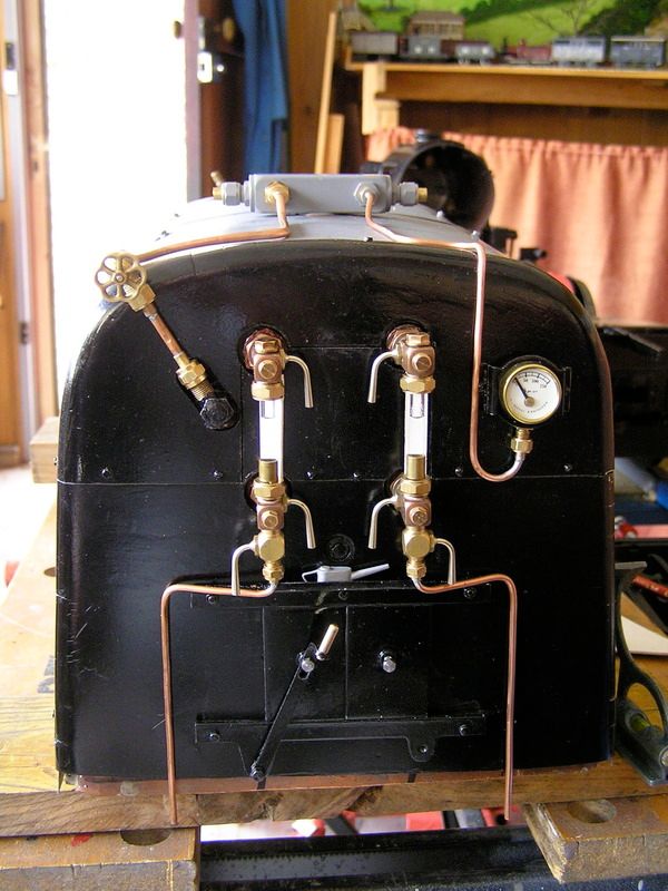 |
|
|
|
Post by Shawki Shlemon on Apr 18, 2015 5:27:30 GMT
Hi Jim , is that enough U tube for the gauge ? Have you checked with your boiler inspector ?
|
|
|
|
Post by Deleted on Apr 18, 2015 7:17:06 GMT
Ahh...a thing of beauty Jim....your backhead is coming along leaps and bounds.... Shawki I didn't realise that there was a code for the gauge syphon?....mind you I've only fitted a commercial gauge witb syphon included to date....I would be interested to know what the rules state in our code here for when I get to this stage on 4472 if someone here could enlighten me please...?
Nice work Jim
Pete
|
|
|
|
Post by ejparrott on Apr 18, 2015 7:42:16 GMT
Nothing Pete.
|
|
|
|
Post by Jim on Apr 18, 2015 8:11:07 GMT
Hi Shawki,
I'll recheck to make sure.
Jim
|
|
|
|
Post by Cro on Apr 18, 2015 9:28:32 GMT
Looking good Jim, Just needs a fancy pedestal to go with it now  Also I don't think there is any regulation on the syphon its more of a recommendation isn't it? Adam |
|
|
|
Post by Deleted on Apr 18, 2015 10:53:21 GMT
Thanks Edd and Adam...I didn't think there was as I hadn't heard of such, but always worth asking the question...
cheers
Pete
|
|
|
|
Post by Jim on Apr 18, 2015 11:25:23 GMT
I've been keeping a close eye on the development of your brake pedestals Adam and I must say they look brilliant plus in the process there have been some very useful links to photos showing Cab details not usually seen when a general 'snap' of the cab is taken.
This afternoon I completed the three dummy gauges and the mounting plate for them so they will be ready for fixing the backhead tomorrow. The next job will be to do the art work for the dials and for this I'll probably use Print Artist which is the programme I used to create the art work for the head boards.
Jim.
|
|
|
|
Post by ejparrott on Apr 19, 2015 7:44:45 GMT
I don't even recall a recommendation in the regs Adam
|
|
|
|
Post by Jim on Apr 19, 2015 8:01:33 GMT
Our AMBSC code simply states, 'Pressure gauges shall be connected to boilers via a water filled syphon.'
Jim
|
|
|
|
Post by Jim on Apr 20, 2015 6:55:37 GMT
The dummy gauges for the driver's side of the cab have now been fitted to add a bit more detail to the back head. For those interested the dials for the gauges are based on Perrier's sketches and I suspect were the gauges fitted when the Britannias were new as later photos show a range of changes of gauges and arrangements. The actual 'art work' was done using a programme called Print Artist and involved a few trial reductions to get the correct sizes for the respective gauges before they were printed onto white ink jet decal or transfer paper. The transfers need to be 'fixed' with a coat of clear spray varnish before finally wetting and sliding into place. The first photo shows the gauges in place but without the dials. 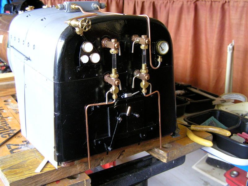 This photo shows the gauges in detail and as Sod would have it the printer's colour cartridge was about out resulting in the speckled green sector on the oil gauge.  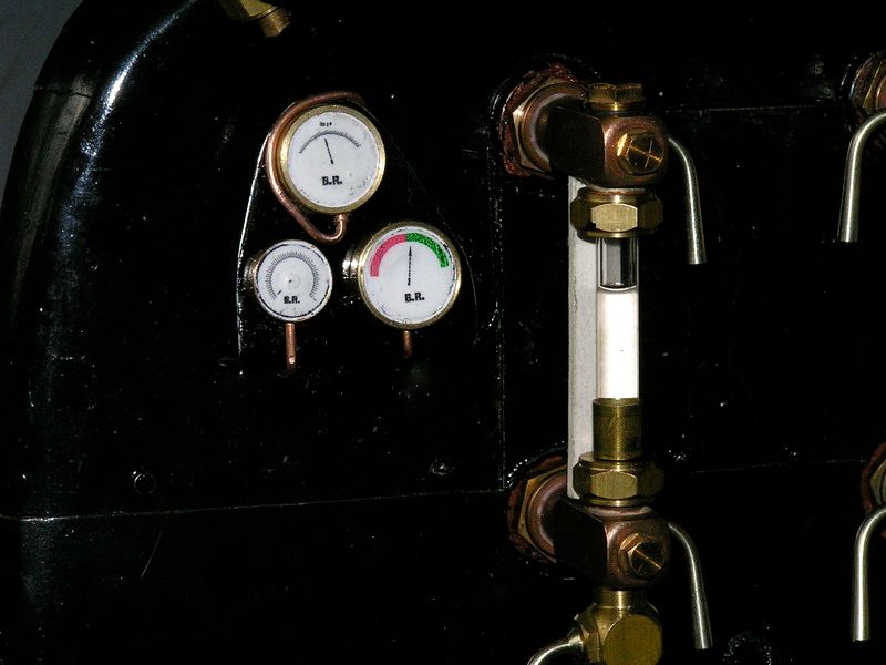 Jim |
|
|
|
Post by Cro on Apr 20, 2015 9:17:35 GMT
Jim,
Gauges look great, the whole backhead is starting to come together beautifully!
Question, is that your blower valve at the top left? I just wonder how close that will end up to the cab roof, knowing the 9f cab is quite low to the boiler I would imagine you could be pretty close here, its also a bit of a shame you aren't putting it on a pedestal, Std cabs always look lost without one.
Great stuff Jim,
Adam
|
|
|
|
Post by Jim on Apr 20, 2015 9:55:59 GMT
Hi Adam, You make a good and valid point there re the valve being close to the roof plus if I'm honest, it is just too big sitting up there. It can be shifted and probably will be as I get further along the road. I'm also looking at how and where to run the pipe from the steam brake to the pedestal as I now have a clear set of drawings for the brake valve to replace the faded part of my Perrier drawings. Then of course there's your drawings of the pedestal which as you say, just begs for the blower valve to be in its rightful place. Now you can see why I need a soothing ale  Jim |
|
|
|
Post by Shawki Shlemon on Apr 20, 2015 10:26:31 GMT
Jim , I am back again with a negative comment , I am sorry about that , I can't see the RED line inside your pressure gauge for operating pressure , its a requirement .
|
|
|
|
Post by Cro on Apr 20, 2015 11:36:28 GMT
Jim , I am back again with a negative comment , I am sorry about that , I can't see the RED line inside your pressure gauge for operating pressure , its a requirement . This may be because he might not have done this yet? I didn't do mine until I did the boiler tests when I was testing the gauge.....as you can see in the photo below, no red line... Jim are you hoping to do the brake valve on top of the pedestal as the steam brake? This is the 9f showing the vacuum brake ontop of the pedestal and then the steam brake above it 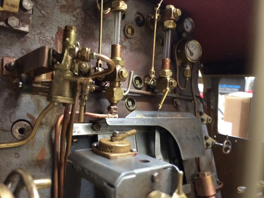 Adam |
|
|
|
Post by Jim on Apr 20, 2015 12:08:34 GMT
No need to apologize Shawki, as you say it is a requirement that the pressure be marked with a red line. I haven't done it yet as I'm really still assembling components to see how they look after sitting in boxes for ages.
Jim
|
|
|
|
Post by Jim on Apr 20, 2015 12:25:28 GMT
That is a superbly detailed scale backhead Adam, I'm green with envy. This is the non working brake pedestal I made up from Perrier's drawings some time back when I was still assembling the boiler. Now I have the details of the valve and thanks to your posts, the actual appearance of the pedestal I will remake it all. 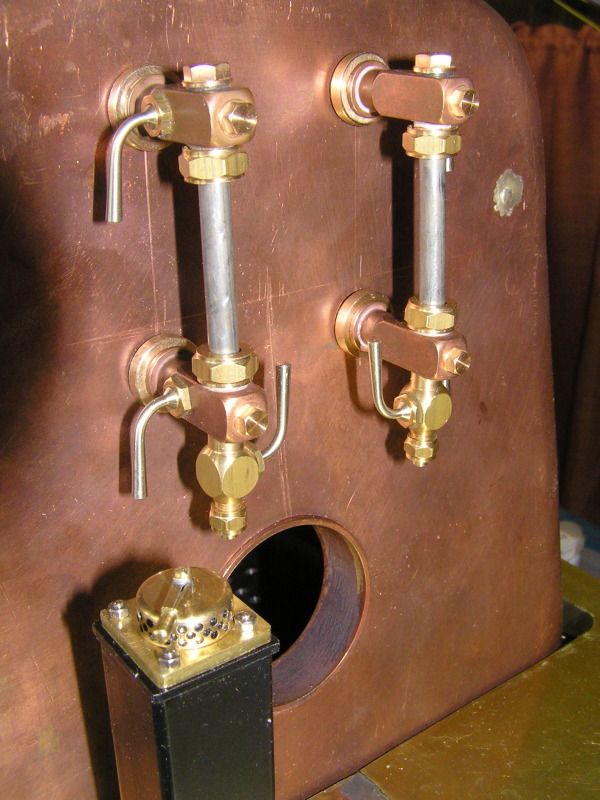 Jim |
|
|
|
Post by Jim on May 3, 2015 6:21:18 GMT
Just a quick update. I've now completed much of the backhead detail with the dummy carriage warming pressure gauge now in place along with the last of my washout plugs, I'll need to make some more shortly. I wasn't all that happy with the location of the blower valve above the left hand gauges so have decided to re pipe it to be in its correct place on the brake stand. The brake stand is on the 'to do' list and thanks to Adam's photos and work I now have a clear idea of what the 'hidden' side of the stand looks like so there's no excuse now. I've also had the boiler up to 100 psi on air to check the Everlasting blowdown valve and gauge glasses. The glands on the glasses just needed slight tightening to seal but the Everlasting valve started to drip steadily again so I will replace it with a standard tap style valve. As it all stands now the cleading can be removed in segments or completely if needs be without disturbing any of the fittings. 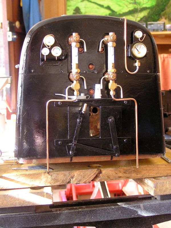 Jim |
|
|
|
Post by Deleted on May 3, 2015 8:14:56 GMT
On a full size engine the syphon tube is used to protect the pressure gauge from the worst of boiler heat and to stabilise the gauge reading .
Strictly the actual details of the syphon tube needed depend on how far the gauge is from boiler connection and the layout of the connecting pipe .
I doubt that many syphon tubes were actually designed though - they just evolved over time into a few standard shapes which were known to work .
Whether model size syphon tubes work like full size ones is anyone's guess .
Full size gauges often had a shut off cock for safety in case a Bourdon tube burst . Not a common failure but it did happen occassionally .
|
|
|
|
Post by ejparrott on May 6, 2015 11:23:48 GMT
At least one of the TR engines has the feed tube wrapped over the top of the gauge and back down the other side to the connection point
|
|