|
|
Post by Jim on May 1, 2017 23:35:49 GMT
The reason I'm using a former John is simply because it's a method that works for me, I used the same method to do the sides of the tender on the Burrell. The formers for the Burrell, the Britannia's boiler and the current task were all made from MDF which again is a material I find easy to work with and more than adequate for the task not to mention the savings on soothing ales.  Jim |
|
|
|
Post by Jim on May 3, 2017 7:27:43 GMT
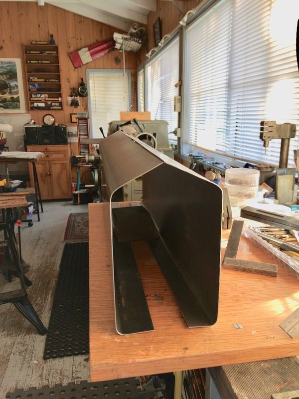
Today saw the completion of folding the first of the tender's sides. The former I find useful for setting the bends in the right places with a move to a simple bending jig as the photo shows (missing the G clamp to pull the bar down) A friend lent me a bending jig but sadly it was just a whisker too short.   I'm pleased with how it has worked so far. Jim |
|
|
|
Post by Jim on May 4, 2017 6:57:05 GMT
Back from our regular Thursday lunch and updates on the various projects being undertaken I decided to form up the second side for the tender. As always things go faster second time round. The photo shows the sides ready for trimming.  The next job once the sides are ready to be fitted will be drill the myriad holes for the dummy rivets. Starting to get a bit excited after seeing one side temporarily fitted to the tender it really fleshed out that empty space behind the loco.  Jim |
|
|
|
Post by Jim on May 5, 2017 12:35:02 GMT
A little more progress with the excess trimmed from the tender sides using the small slitting saw. Next task will be to start assembling the sides to form the main body of the tender.  Slowly getting there. Jim |
|
|
|
Post by GWR 101 on May 5, 2017 17:53:58 GMT
Hi Jim, great work as usual........ do my eyes deceive me or are you climb milling there ? Regards Paul
|
|
|
|
Post by 92220 on May 5, 2017 19:47:02 GMT
Yes he is. I almost always climb-mill when using the side flutes of endmills. I find my cutters stay sharp a lot longer because the teeth are cutting, not scraping/rubbing. The table on my mill is a heavy brute so doesn't tend to get pushed by the cutter. If your mill table slides freely, put on the brake to apply a resistance to sliding. Use a shallower cut and slightly slower feed, and the resultant finish should be better than conventional up-cut milling.
Bob.
|
|
|
|
Post by Jim on May 5, 2017 21:47:31 GMT
Your eyes aren't deceiving you Paul, I'm guilty as charged.  Bob is right too in what he says about climb milling and the techniques to stop 'grabbing' which are very handy to keep in mind for 'next time'. In my example of climb milling or in this case 'in cutting' the saw is cutting into the former which is supporting the thin metal sheet to stop it deforming away from the saw as would very quickly happen when 'out cutting' if starting from the opposite end of the sheet feeding R to L. The saw is running at 150 rpm which is the slowest speed on my mill. Jim |
|
|
|
Post by springcrocus on May 5, 2017 22:13:47 GMT
If you look closely at Jim's photo, try to picture the angle created by the inner face of the cutting tooth and the edge of the workpiece. The closer to 180 degrees that you can get this, the less likelyhood of drawing the work forward. If Jim's cutter had started to pull, he would have wound the cutter in a bit deeper to get a steeper angle of attack, thus alleviating the problem.
Regards, Steve
|
|
|
|
Post by Jim on May 5, 2017 22:42:32 GMT
That's a very good point Steve especially for anyone using a slitting saw for the first time and unfamiliar with the antics they can get up to. I got a reminder of this when I felt a slight catch as I started into the first cut. I immediately backed off to take the table in to give the depth of cut shown in the photo.
Jim
|
|
|
|
Post by simplyloco on May 6, 2017 8:26:14 GMT
I don't do climb milling unless absolutely unavoidable. This is because early in my career the 1" end mill I was using in a large universal mill started walking up the face of the large block of steel being machined, breaking up as it went, throwing sharp chips into my face. The forces generated rotated the milling head some 30 degrees off the vertical!
I don't do climb milling...
John
|
|
|
|
Post by GWR 101 on May 6, 2017 8:51:14 GMT
Thanks for the information, I must admit that like John I also avoid using this approach perhaps it is a left over from my apprentice days (when Adam was a lad, no not our Adam !). I realise that with modern kit and anti backlash equipment this is now a recognised method of milling. Perhaps some day I might have the need to adopt it, but I am afraid it just goes against the grain.  I will get my coat, Paul. |
|
|
|
Post by Jim on May 6, 2017 11:57:33 GMT
Hi Jim, great work as usual........ do my eyes deceive me or are you climb milling there ? Regards Paul Hi Paul, Actually using the slitting saw in the way I do is exactly the same as a circular saw is set up on a saw bench where the saw's cut is downwards toward the material being cut supported by the bench or, as in my case toward the MDF former which is doing the same job as the saw bench in supporting the steel being cut. I don't think you can compare using a slitting saw in this manner with climb milling with an end mill. Jim |
|
|
|
Post by 92220 on May 6, 2017 12:59:09 GMT
I did say I almost always use climb milling. I should have also said that it is with cutters of 1/2" dia and under. Over 1/2" I do use conventional up-cut milling for exactly the same reason John quoted, above. I do also limit the depth of cut.
Bob
|
|
|
|
Post by Jim on May 6, 2017 23:10:50 GMT
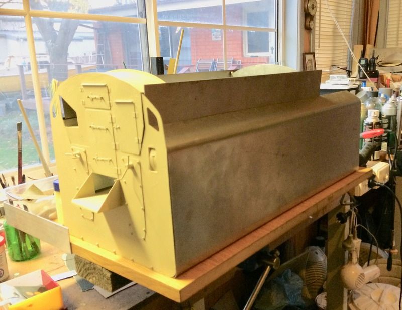
I couldn't help myself as I just had to cobble all the parts together to see how they fitted and get a photo before the whole lot fell apart....again! Not very professional I know but what the heck I'm having fun.  In the process of this trial fit I've found the left hand side of the bunker for some reason isn't sitting properly so will have to recheck to see if it has twisted. In the worst case scenario I may have to disassemble the bunker, I hope note but if it has to be done so be it.  Jim |
|
|
|
Post by simplyloco on May 6, 2017 23:21:45 GMT
I couldn't help myself as I just had to cobble all the parts together to see how they fitted and get a photo before the whole lot fell apart....again! Not very professional I know but what the heck I'm having fun.  In the process of this trial fit I've found the left hand side of the bunker for some reason isn't sitting properly so will have to recheck to see if it has twisted. In the worst case scenario I may have to disassemble the bunker, I hope note but if it has to be done so be it. Jim I think it looks wunderful! Because I've put cladding on the LBSC boiler I have to increase the size of the tender to suit the changed dimensions. We shall see how it turns out. JB |
|
|
|
Post by 92220 on May 7, 2017 8:03:30 GMT
That is looking good Jim!! I've just got the drawings for the water treatment equipment. I am in the process of doing the drawings for it. When finished I'll post it for you and those who are interested in adding the access manhole to the B1G tender top.
Bob
|
|
|
|
Post by Jim on May 7, 2017 8:26:04 GMT
I think it looks wunderful! Because I've put cladding on the LBSC boiler I have to increase the size of the tender to suit the changed dimensions. We shall see how it turns out. JB Thanks John for your comment especially about the cleading on your loco. I had a similar problem with the canopy on my tender in that as drawn it didn't match the curvature of the cab roof plus it was slightly low. I think that with plate work much as we try, things such as bends, angles etc aren't always as precise as the lathe and milling work we do. While you try to keep things square as you hammer, roll and bend the plate things do go slightly out and that has been the case with tender bunker. After getting all the components squared up and secure on a flat surface and carefully looking and checking I found the problem wasn't with the bunker thankfully but with a slightly out of square end on the left hand tank side. The result was that in fixing the offending side to the front plate then puling the sides into the rear plate the front skewed and threw one side of the bunker out. Before I trim the side to fit I think a nice soothing ale and a good night's sleep might be the way to go then a re check in the morning just to be sure I have found the problem. Jim. |
|
|
|
Post by 92220 on May 7, 2017 11:19:44 GMT
Hi Jim.
Remember I said I'd seen a drawing with that funnel and pipework on the front of the tender, next door to the water scoop indicator. I've just found it!! That funnel and pipe are all part of the water treatment equipment, NOT the ale dispenser you were hoping for!! I've started drawing up the parts so will post when I have finished.
Bob
|
|
|
|
Post by Jim on May 7, 2017 12:04:55 GMT
Hi Jim. Remember I said I'd seen a drawing with that funnel and pipework on the front of the tender, next door to the water scoop indicator. I've just found it!! That funnel and pipe are all part of the water treatment equipment, NOT the ale dispenser you were hoping for!! I've started drawing up the parts so will post when I have finished. Bob Bob I think there must be a mistake in the drawings. I'm sure I've seen a sign above one of those spouts saying "Old Peculiar..for soothing enginemen's throats" Jim. Look forward to seeing the drawings, were they for the BRG tender? |
|
Lisa
Statesman
 
Posts: 806 
|
Post by Lisa on May 7, 2017 12:22:46 GMT
Hi Jim. Remember I said I'd seen a drawing with that funnel and pipework on the front of the tender, next door to the water scoop indicator. I've just found it!! That funnel and pipe are all part of the water treatment equipment, NOT the ale dispenser you were hoping for!! I've started drawing up the parts so will post when I have finished. Bob To be fair, with the right treatment the water would become ale.  |
|