|
|
Post by fostergp6nhp on Nov 4, 2011 16:14:56 GMT
I have spotted 4 errors on my drawings which are the redrawn ones that were supplied by A J Reeves in the late 1970's.
1. The horns for the radial truck are shown with a cutout in the bottom edge at the middle for bolted projections of the side control unit to engage in. Full size has no cut out for this, the side control is bolted in the horns.
2. The radial truck horns are shown on the drawings as being solid on the curved faces. Full size they have 2 rectangular cutouts in the faces.
3. The cylinder drawing has the covers for the cylinders dimensioned to have a spigot 3/64" tall from the joint face into the cylinder bore, the spigot is releaved at the port down to 3/64" from the joint face! A bit of maths shows that there is 3/16" at each end for the clearance volumne and the cover spigot. I would suggest 3/64" from the joint face for the scallop and a total hight of the spigot of 1/8" from the joint face.
4. The valve liners have tapered bores right to the end face, a small depth parallel bore and the valve chest covers have then got a bore for their tweaked diameter registers to locate in.
No's 1 & 2 can be seen in the 5199 photo's that were on here.
|
|
|
|
Post by Laurie_B on Nov 5, 2011 10:58:19 GMT
Thanks for the info.I've found exactly the same,regarding the radial truck,and the cylinder covers.I also wish that the keeps for the truck had been left 'solid' and not had the oil recess cast in them.Metinks it makes it trickier to bore out accurately for the axle. Additionally,I find that the p.c.d. for the cylinder cover bolts is too close to the 2-3/64"dia x 3/64" relief on the outside of the joint face.There is a risk of the 'No.33' holes 'breaking through'. The dimension of 1-13/32" for the slide bar locations (and the corresponding the crosshead depth) is slightly too small,though the slide bars could be shimmed as full size practice. The flange on the bracket for the vacuum pump is wrong,as previously reported. If you make the brake cylinder piston rod to the drawing it is then impossible to fit the bottom cylinder cover!Mod required! But apart from all that.....so far so good!  I've just made a start on the pony truck and that seems to be going fairly well.The inclined faces for the side control could be a challenge. |
|
|
|
Post by fostergp6nhp on Nov 5, 2011 14:24:27 GMT
Ref the brake cylinder piston rod. On mine i modified the design, instead of a boss on the end i threaded it to fit a boss that way, further construction will prove if this will work or that i need to modify the piston and make a new rod with a boss on the bottom and a thread at the top. Diverting to BR coach brake cylinders the rod had a boss on the bottom and was threaded into the piston which had a blind hole in the piston so there was no leakage thro the thread, the rod could not unscrew in service as presumably the rolling ring seal made sure the piston could not rotate and screw off the rod. We used to remove the rod for fitting the cylinder to the coaches as it got in the way.
|
|
|
|
Post by Rex Hanman on Mar 26, 2012 16:24:19 GMT
One for the rivet counters...  While re drawing the trailing hanging plates (I'm building in 7 1/4") I could not get one of the rivets to look right. My drawings show, on sheet 6, a rivet roughly central in the "trianglular" part. Photographic evidence shows there was no rivet here!  Not the best photo but I think you will see what I mean.  |
|
|
|
Post by Laurie_B on Mar 27, 2012 11:20:57 GMT
Hi Rex, Trevor Shortland's/Reeves' drawing T6 does indeed show a rivet in the "triangular" part you refer to,but like yourself I've not found any photographic evidence either. And Andy Clark's excellent set of photos, www.modeleng.org/images/prairie/ do not show this extra rivet either. The drawing in GWR Journal No.5 does show an extra rivet/bolt hole in the area,but I suspect this belongs to an inner face,and possibly not the outer plates. Your 7-1/4" gauge project sounds very interesting! Laurence. Attachments:
|
|
|
|
Post by Rex Hanman on Mar 29, 2012 8:21:02 GMT
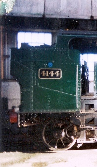
Hi Laurence, Thanks for your reply and for posting a much better picture than I did. The large prairies have always been my favourite. When I decided to build one in 7 1/4" I spent a day at Didcot where 4144 and 6106 were conveniently parked next to each other. I had a good look and took a few pictures. Shortly afterwards I joined this group and one of my first postings was to point out that there is in fact a large square(ish) cut out in the frames where the "joggle" is. This of course made bending my 5 mm thick frames much easier! Sadly, this posting disappeared a long time ago.  I am scaling up Trevor's excellent drawings and have used where possible the castings from Reeves for the mogul. This means that the cylinders/saddle castings are not strictly correct but I am not building a competition or exhibition model. One major problem was finding castings for the trailing wheels. The Reeves "Dart" wheels are the right size but have the wrong number of spokes. Polly now do an "improved Dart" and recently I obtained a cracking pair of wheels from them, so it's all steam ahead! My father was a fireman and driver at Gloucester (Horton Road). 4141 was a Gloucester engine all its life so it was the obvious choice for me as it is inconceivable that he wouldn't have driven it countless times. I am therefore indebted to you for posting the lovely shot of her, one to add to my collection if you don't mind. I haven't got very far, just a rolling chassis but I retired in September so hope to make real progress now, but something always gets in the way.  Must go, got to cut the grass.....  |
|
|
|
Post by donashton on Apr 2, 2012 19:24:47 GMT
What an interesting and informative thread to read, especially as I have closely seen 4141 under major overhaul during the past two years. I'm a little surprised that nobody has mentioned full size drawings to help with rivet patterns and all manner of other items. Beware, though - I have come across things on the drawings that are different in practice.
My interest in the 41 stems from my involvement in building 4709 (12" to the foot), as almost the whole front end and considerably more is common with the 41, so on each visit I have peered at many details.
I wish the best for all these model prairies - super engines.
Don
|
|
|
|
Post by Laurie_B on Apr 3, 2012 9:40:53 GMT
Hi Rex. Thanks for the info about your 7-1/4"G project;it should make a very impressive loco.I'm at about the same stage as yourself with my 5"G version-not quite to rolling chassis stage yet;I've almost finished the pony truck. There is an impressive 7-1/4"G 'Large Prairie' model (built by H.C.Powell) coming up for sale by auction later this month. Hi Don. I did have a look at the GA drawing reproduced in the GWR Journal but couldn't see the extra rivet.I believe some parts for the new 47xx project have come from ex-Barry 'wreck' 4115. Another restoration is of 4150 at Bewdley,on the SVR.They have an interesting website and some useful photos. www.4150.org.uk/ |
|
|
|
Post by Rex Hanman on Apr 3, 2012 17:18:08 GMT
I have also studied the GA in GWR journal No, 5. As a former teacher of "Technical Drawing" it leaves me breathless. How did they do such complex work without the use of CAD? Amazing! Clearly no rivet, I wonder how it crept into Trevor's drawing? The centrefold picture provides a wealth of information, I can look at it for hours!  Laurence, which auction is the prairie in? Don, any idea when 4141 will be back in service? |
|
|
|
Post by donashton on Apr 3, 2012 19:52:34 GMT
Hi chaps,
I suppose the best answer to the rivet is what purpose would it serve?
The front end of 4115 is now the front end of 4709. Also the wheels and many other parts. It's a much more useful fate than the inevitable cutter's torch. Actually, condition was better than expected, which can't be said for 5227.
4141 I saw today and they are working hard to get her completed for the Gala. After that she goes to Ongar with Pitchford Hall. Lots of painting going on - it's one or two nasties with the boiler holding things up.
Don
|
|
|
|
Post by Laurie_B on Apr 4, 2012 9:56:40 GMT
|
|
|
|
Post by Rex Hanman on Apr 4, 2012 21:00:28 GMT
Thanks Laurence, it will be interesting to see what it goes for!
|
|
|
|
Post by Rex Hanman on Apr 25, 2012 16:42:53 GMT
The centrefold picture provides a wealth of information, I can look at it for hours!  Laurence, which auction is the prairie in? Having studied the centrefold pic further I notice that the front driver has C HALL painted or chalked on it.  Can't be a set from a hall as they are bigger. Strange! Laurence, just been to the auction, the prairie went for £30,000! Strewth!  |
|
|
|
Post by Laurie_B on Apr 25, 2012 19:31:58 GMT
The centrefold picture provides a wealth of information, I can look at it for hours!  Laurence, which auction is the prairie in? Having studied the centrefold pic further I notice that the front driver has C HALL painted or chalked on it.  Can't be a set from a hall as they are bigger. Strange! Laurence, just been to the auction, the prairie went for £30,000! Strewth!  Rex,as you say,in the photo the leading driver couldn't have come from a Hall class,and I've just noticed in the photo,the pony wheel has the same letters added with what looks like '21' in front.Odd indeed! I followed the auction on the internet and was astonished at the prices realised.Some serious collectors with deep pockets must have been there. I did here the auctioneer mention that the son of the builder (Harry Powell) was at the auction,prepared to give details of the history of the loco to the new owner. |
|
|
|
Post by Rex Hanman on Apr 26, 2012 12:42:32 GMT
Wow, I hadn't noticed that it was also on the pony truck wheel.  I have often wondered what the thing on the wall behind was. It looks like a letter "V". Maybe the "C HALL" refers to another area or building where the pony wheels and front drivers are to be moved to for attention? The writing on both wheels is in roughly the same place, suggesting that it was applied where the engine is. Back to drawing errors, something else has leapt out at me. The brackets,13 on sheet T6, should have a triangle cut out at the top to match the one at the bottom. Hardly vital, but more importantly, brackets 11 and 12 are shown in the wrong place and upside down. The drawings show the top one flush with bracket 15 but as can be clearly seen in the picture it should be the other way up and lower down. I suspect the bottom one may also be incorrect. Mine are not finally fitted so I may correct them as this will make fixing them much easier!  |
|
|
|
Post by fostergp6nhp on Jan 12, 2013 11:32:07 GMT
Looking at the pics on the 47xx web site www.knowles-cadbury-brown.co.uk/4709/pages/Archive%20News.html there is some pics that show the stay for the pony truck/driving axle compensation, there should be angle irons top and bottom horizontally that are not on our drawings. Also on bracket 9 the front face should not be solid but cut out and there should be a round hole in the bottom plate inside front corner which on the r/h side the vacuum pipe passes thro. Also there should be a round hole in the buffer beams behind the buffers. Also the horn stays should not be fixed to the horn cheeks with a single bolt but by 2 studs & nuts at each end, scroll further doun on the link above to see. |
|
|
|
Post by Rex Hanman on Jan 12, 2013 12:37:09 GMT
Thanks for that.....I've just spent a pleasant hour looking at that website. ;D I already have the holes in the buffer beam as my building stand fixes through the beam rather than using the buffer stocks. I thought "No one will see them once the buffers are fitted"  Can't do much about the horn stay fixings though....too late! |
|
|
|
Post by fostergp6nhp on Jan 12, 2013 21:26:55 GMT
I hope to be visiting 4150 soon for a shufti and to check out some issues mantioned on here.
|
|
|
|
Post by fostergp6nhp on Feb 6, 2014 18:50:17 GMT
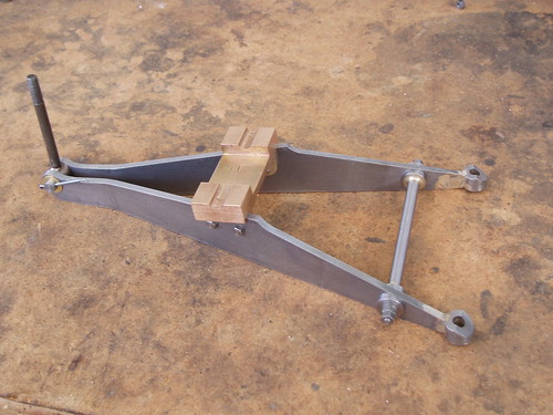
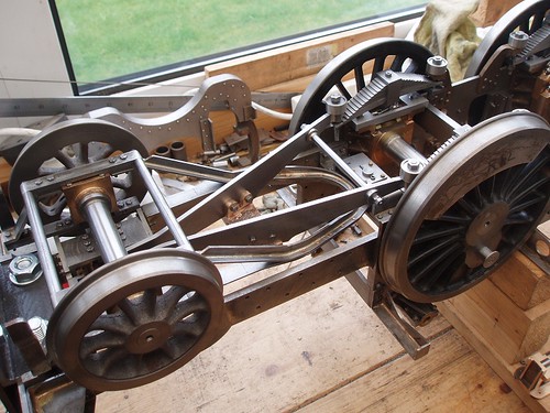
Pony truck equalizing beam. The bosses for the spring hanger bolts should be a bolted casting with a long round bar and 4 nuts to fix them in place and the bar then acts as a stay for the 2 ends of the beam.
|
|
|
|
Post by Laurie_B on Feb 6, 2014 21:06:28 GMT
Pony truck equalizing beam. The bosses for the spring hanger bolts should be a bolted casting with a long round bar and 4 nuts to fix them in place and the bar then acts as a stay for the 2 ends of the beam. Just finished the equalizing beams.I wasn't too sure how the rear bosses were attached.The Shortland/Reeves drawings show the bosses silver soldered to the ends of the beams,but show nothing of the long round stay mentioned or its bosses,which are shown on the Swindon GA drawing.Attached are two images of my interpretation of the drawings for the equalizing beams.On another forum,I think Rex has been having fun with his 7-1/4" gauge version.Hope the shoulder is better soon,Rex!   |
|