|
|
Post by delaplume on Feb 19, 2019 18:43:02 GMT
|
|
|
|
Post by RGR 60130 on Feb 19, 2019 19:33:54 GMT
Hi Roger, Quote}---Your daily routine is predictable and ordered.... Daddy's yacht eh? Obviously not a Merchant vessel or an FPSO! Reg |
|
|
|
Post by David on Feb 19, 2019 21:40:14 GMT
That looks brilliant after the finishing pass.
If anyone knows how to get F360 to just cut along a sketch line to a particular depth I'd love to know.
|
|
|
|
Post by Roger on Feb 19, 2019 22:47:28 GMT
This is the mess left at the end of the Parallel Finishing rough pass which has a step over of 0.25mm leaving 75microns to finish  20190219_201540 20190219_201540 by Anne Froud, on Flickr ...and this is what's lurking under the swarf.  20190219_201607 20190219_201607 by Anne Froud, on Flickr You can see the amount still to come off the top and the difference in finish to the bottom side.  20190219_201710 20190219_201710 by Anne Froud, on Flickr And this is both sides finished now. The next step is to drill and tap the M1.4 fixing hole and the cross hole for the flanges with its registration pockets. This is the tricky part done though.  20190219_223823 20190219_223823 by Anne Froud, on Flickr |
|
|
|
Post by delaplume on Feb 20, 2019 2:36:12 GMT
Hi Roger, Quote}---Your daily routine is predictable and ordered.... Daddy's yacht eh? Obviously not a Merchant vessel or an FPSO! Reg Hi Reg.........No, it was courtesy of The Grey Funnel Line.......best known for their "Off piste" routes and habit of shooting at other ships !!..LoL !! |
|
|
|
Post by Roger on Feb 20, 2019 21:47:44 GMT
I've decided to scrap that first valve, the height didn't work out quite right, although it wasn't initially clear what the problem was. It turns out that there are several things contributing to that, not least the backlash compensation which was set too high. I've discovered that my 1micron resolution digital plunger clock fits my miniature magnetic base, so I used that to check all of the axes and make any adjustments. I'd got the X/Y ones almost spot on, so why the Z was so far out is a mystery. Anyway, I've used the opportunity to make a few changes to the machining strategy and the next one is well on the way to being machined. I've just got the finishing cut to do tomorrow and I'll be back where I was last night but hopefully with a better result. So while that's being machined, I've moved on to look at the black elbow with the ribs. It turns out that this isn't as simple as it looks because the bore reduces as does the outside diameter and the flange is smaller where it meets the injector.  DSCN5687 DSCN5687 by Anne Froud, on Flickr That's a real pain, because it means modelling it with a loft using guide curves (my nemesis) or defining multiple sections for the loft to pass through. Worse than that, you can do the inside and outside in one loft, so the outside needs to be done and then hollowed out. Here you can see the planes defined at every 15 degrees with the blue rings showing the sketches I've created. There's just room to shoe horn in a 1mm secion 'O' ring for the seal and M1.4 studs and nuts to hold it all together.  Injector water inlet elbow Injector water inlet elbow by Anne Froud, on Flickr This is probably one of the most difficult things I've had to machine. The difficulty is knowing how to hold it. In the end I've decided to slightly stretch the flange at the top of the picture and hold it on that end for machining both sides of each half. Obviously you can't make this in one piece. 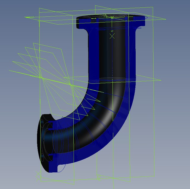 Sectioned elbow Sectioned elbow by Anne Froud, on Flickr I've found that I can machine each half out of a piece of 22mm diameter stock, so that's not too bad. Again, there are some very slender features on this part where the O-ring is seated, so this will again be made from Phosphor Bronze so it's strong enough. |
|
jma1009
Elder Statesman

Posts: 5,901
|
Post by jma1009 on Feb 20, 2019 22:23:57 GMT
Hi Roger,
In our sizes, you have to remember that for a medium sized standard injector the water supply to the injector is commonly accepted to require a ID bore of 5/32" dia ie 3/16" OD thin wall piping. This applies equally of course to the passageway to the water valve.
It is only when dealing with small 10 oz per minute injectors that I found a throttling of the water valve is required when testing these on a loco much larger than the injectors were intended for. The same set up was used to test 18 oz per minute and 12 oz per minute injectors, but my notes and memory do not state/recall any throttling of the water supply injector valve.
You could make the water valves out of brass.
Personally, given the atrocious hard water in Sussex where you live, I would want to be able to swap over injectors for spares very quickly and simply and without having to fuss about with flanged joints with 10 BA bolts and nuts or whatever Metric fastenings you propose to use. I can swap over an injector on a loco in steam in about a minute, though this has been when testing injectors.
The hard water in your part of Sussex is not favourable.
Cheers,
Julian
|
|
|
|
Post by Roger on Feb 20, 2019 23:01:21 GMT
Hi Roger, In our sizes, you have to remember that for a medium sized standard injector the water supply to the injector is commonly accepted to require a ID bore of 5/32" dia ie 3/16" OD thin wall piping. This applies equally of course to the passageway to the water valve. It is only when dealing with small 10 oz per minute injectors that I found a throttling of the water valve is required when testing these on a loco much larger than the injectors were intended for. The same set up was used to test 18 oz per minute and 12 oz per minute injectors, but my notes and memory do not state/recall any throttling of the water supply injector valve. You could make the water valves out of brass. Personally, given the atrocious hard water in Sussex where you live, I would want to be able to swap over injectors for spares very quickly and simply and without having to fuss about with flanged joints with 10 BA bolts and nuts or whatever Metric fastenings you propose to use. I can swap over an injector on a loco in steam in about a minute, though this has been when testing injectors. The hard water in your part of Sussex is not favourable. Cheers, Julian Hi Julian, Thanks for that, I've got 5mm from the tank, but that narrows to 4.2mm which is a little below the 3/16" (4.76mm) you mention. I don't think it's feasible to go quite that big with the scale injector body. If I size the injector on the small side, hopefully that won't be an issue. I'm not sure what size injectors to make yet, but they are likely to be smaller rather than larger. So far I've not driven a locomotive where the injector didn't seem too big. It seems counter productive to have them larger than necessary to just cope with the maximum load. The whole issue of swapping injectors is something I'd like to avoid for the reasons you mention. It's not something I'd want to do at the track. Fortunately, this is one case where the axle driven pump will save the day if there are any issues. I have a few ideas about injector materials and design that might prove to be less susceptible to the build up of scale. I'm sure I've also read about someone flushing the injectors through the overflow with something to break down any deposits. I don't think it's possible to make scale injectors that can be swapped quickly. The alternative solution is to make those as dummies and to have the real ones hidden between the frames. Hopefully that won't be necessary. It's all an adventure, and I can honestly say that I don't know what the outcome will be. If it's at all possible to make reliable scale injectors that don't need changing, that seems to be the most desirable solution. The problem with making fine scale parts from Brass is that it's very brittle where the sections are small or where there are threads. The valve has a tiny thread in the boss that holds the gland part in place. I don't think this would be man enough in Brass. Although Phosphor Bronze is slightly harder to machine, it's much more durable. |
|
|
|
Post by 92220 on Feb 21, 2019 21:44:22 GMT
Hi Roger.
Have you got a works drawing for the injector? If not I have works drawings of both the 10X and the 11X injector, whichever is relevant to 1501.
Bob.
|
|
|
|
Post by Roger on Feb 21, 2019 21:50:18 GMT
Hi Roger. Have you got a works drawing for the injector? If not I have works drawings of both the 10X and the 11X injector, whichever is relevant to 1501. Bob. Hi Bob, Many thanks for the kind offer, but I've got the works drawing. Mind you, there are variations and the two on 1501 are slightly different. |
|
don9f
Statesman
 Les Warnett 9F, Martin Evans “Jinty”, a part built “Austin 7” and now a part built Springbok B1.
Posts: 960 
|
Post by don9f on Feb 21, 2019 23:09:26 GMT
Hi Roger in your photo above, the outer water valve has “SVR” cast into it, so maybe was made new for the engine during its restoration, whereas the inner one looks “battered” and much older....maybe it’s the same with the injectors as the one in the photo looks new-ish....ie unbattered!
Don
|
|
|
|
Post by Roger on Feb 21, 2019 23:20:40 GMT
Hi Roger in your photo above, the outer water valve has “SVR” cast into it, so maybe was made new for the engine during its restoration, whereas the inner one looks “battered” and much older....maybe it’s the same with the injectors as the one in the photo looks new-ish....ie unbattered! Don Hi Don, That sounds entirely possible, they seem to swap any fittings round with whatever's to hand. The water gauge and brake valves are different in some photos too. As long as the shape is broadly right I'll have to live with it. Hopefully the whole arrangement can be made to look plausibly like the real thing while working reliably too. Only time will tell. |
|
|
|
Post by delaplume on Feb 21, 2019 23:21:29 GMT
Hi Roger. Have you got a works drawing for the injector? If not I have works drawings of both the 10X and the 11X injector, whichever is relevant to 1501. Bob. Hi Bob, Was the 11x a re-starting injector ??.........How many injectors did a 9F have ??.........I'm aware they had an exhaust steam injector so did they have 1 live steam or 2 live steam fitted as well ??......... Hi Roger, Just a point to bear in mind re}--- Heritage locomotives....Many by now will have spent more time in private hands than when operated by BR or original owners and just like a used car they may have had repairs done or parts fitted that were driven by practical or operational needs so might not be visually correct..... One example being the water pipe adaptor on the end of the injector overflow pipe........This was part of an ongoing programme at B'north so that the high pressure water supply could be used to fill a boiler after it's washout far quicker than the traditional hose wedged into a opened mudhole ....I think they put some on 1501 ?? Thanks guys Alan |
|
|
|
Post by delaplume on Feb 21, 2019 23:25:43 GMT
Hi Roger in your photo above, the outer water valve has “SVR” cast into it, so maybe was made new for the engine during its restoration, whereas the inner one looks “battered” and much older....maybe it’s the same with the injectors as the one in the photo looks new-ish....ie unbattered! Don Might just have been one of mine !!!-----although most owner groups have their own machinists and my work was mainly on the contract side.......So although I did do some water valves they were probably for A.N. Other Heritage line that Ray Tranter had organised... |
|
|
|
Post by delaplume on Feb 21, 2019 23:38:13 GMT
|
|
don9f
Statesman
Les Warnett 9F, Martin Evans “Jinty”, a part built “Austin 7” and now a part built Springbok B1.
Posts: 960
|
Post by don9f on Feb 21, 2019 23:59:59 GMT
Hi, I’m sure that Bob will have all the details of the correct injector sizes etc. but for information, during the restoration of 92214, we could not obtain (or afford anyway) a correct Davies & Metcalfe Class ‘K’ exhaust steam injector for it, so made do with two live steam injectors, same style as the one in Roger’s photo. I think they were 11x’s but not certain. A genuine ex BR one that was all battered, came our way courtesy of the SVR, plus a brand new one was obtained from the then Hugh Philips Engineering Co. This one had “HPE” cast into its body and if you ignored batterdness, was more or less the only way of distinguishing it from the BR one.
The full size ones are very reliable injectors and I do hope Roger and Adam can each make their own versions equally so!
Cheers Don
|
|
|
|
Post by Roger on Feb 22, 2019 9:12:22 GMT
I think Alan and Don's comments nicely show the futility of trying to accurately model anything from how it is in preservation. It's not something I'm overly bothered about to be honest. As long as I can make a really good likeness of something that's known to have been on the locomotive at some point in the past 20 years then I'm happy with that. In my opinion, too much emphasis on absolute accuracy is the road to the loony bin. Maybe if a locomotive is in a museum, unchanging and unused, you could do it, but not if it's a working locomotive.
1501 has had a new bunker, with different numbers of rivets, different injectors, brake and water valves, and probably much more in preservation. Short of going up each week and keeping up with the changes, you have to accept that it's going to be a moving target and actually, who cares? Before embarking on this project I had no idea that this was the sort of thing that went on.
|
|
|
|
Post by delaplume on Feb 22, 2019 9:39:50 GMT
Quote}---"you have to accept that it's going to be a moving target and actually, who cares?".........Alas, it's the RIVET COUNTERS in life and yes, it really can get VERY HEATED at times !!......
I sometimes get involved with the 4mm side of Railways and it can be just as bad there as well......A few years ago it was reported in the National Press AND on TV that two, fully grown, family men were literally at each others throats in public over a trivial matter concerning the EXACT LIVERY on a class 45 Diesel !!............Sad but true...........Be prepared for this to happen to you at some time or the other when you eventually get your 1501 in steam and on the rails...........It's usually when you are in the station and a member of the Adoring Public can't constrain himself any longer and feels "Duty bound" to point out your model's various indiscretions !!.........When that happens to me I turn Nelsons ear to him......Then make a point of chatting amiably with the people near to him.....Works every time ...I bet everyone reading this will know of such a person in their own club ??
NIL DESPERANDUM etc etc...
|
|
|
|
Post by 92220 on Feb 22, 2019 9:40:05 GMT
Hi Alan.
Evening Star has always been fitted with 2 injectors..... a Davies & Metcalf Type K exhaust injector and a No 10X live steam restarting injector. The 11x restarting injector was used on 10 engines from 92087 to 92097. I'm not 100% sure of the numbers though, as the text on the 11X drawing is very pixelated. The 10X and 11X actually use the same casting anyway, so are identical in appearance. It's the internals that make them different.
Hi Don.
The Davies & Metcalfe drawings for the Type K exhaust steam injector were lost and they only had a partially redrawn copy, when they wanted a new Type K for the Duke of Gloucester. The preservation society paid for the drawings to be completed and then had a new casting made, to end up with a brand new Type K Exhaust Steam Injector. Must have cost a fortune!! I tried to get a copy of the drawing but Davies & Metcalfe, although agreeing to provide me with a copy, never did. Whether this was because Duke of Gloucester prevented it being copied, or that the only copy of the drawing was with Duke of Gloucester, I don't know. In the end I managed to find a partially dimensioned BR drawing of the Type K Injector Arrangement. That is probably why you couldn't get a new injector for 92214.....Blame the Duke!!
Bob.
|
|
|
|
Post by Roger on Feb 22, 2019 9:58:50 GMT
Quote}---"you have to accept that it's going to be a moving target and actually, who cares?".........Alas, it's the RIVET COUNTERS in life and yes, it really can get VERY HEATED at times !!...... I sometimes get involved with the 4mm side of Railways and it can be just as bad there as well......A few years ago it was reported in the National Press AND on TV that two, fully grown, family men were literally at each others throats in public over a trivial matter concerning the EXACT LIVERY on a class 45 Diesel !!............Sad but true...........Be prepared for this to happen to you at some time or the other when you eventually get your 1501 in steam and on the rails...........It's usually when you are in the station and a member of the Adoring Public can't constrain himself any longer and feels "Duty bound" to point out your model's various indiscretions !!.........When that happens to me I turn Nelsons ear to him......Then make a point of chatting amiably with the people near to him.....Works every time ...I bet everyone reading this will know of such a person in their own club ?? NIL DESPERANDUM etc etc... Hi Alan, I can certainly see the value in counting rivets to some degree, if you're going to put in rivets, you want them to be spaced sensibly and be the right size. I've counted them myself, especially on the smokebox and bunker, and that's how I discovered that the bunker had changed. The things you mention are why I'm never going to put 1501 into a competition, I can't stand petty comments and nonsense like that. Every locomotive is going to be flawed, one way or another, you don't need someone trying to score points over some detail. |
|


