|
|
Post by Roger on Mar 28, 2020 11:43:03 GMT
You could do a central oiling system, wick feeds with pipes leading to the axle boxes and eccentric. The pipes to the axle boxes could be arranged so the oil drips directly into the reservoir, the eccentric could be connected by a piece of silicone hose This is true, I've seen it done on Bill Perrett's SPEEDY, but I think it's over complicated and unnecessary for mine. All I need is to be able to oil the two eccentrics and the pump barrel once at the start of the run. I can get to the axleboxes, and everything else is accessible. |
|
|
|
Post by Roger on Mar 28, 2020 12:04:29 GMT
After much agonising, these are the three locations I've chosen for the oiling points. They consist of an M4 tapped hole in the frame, into which is screwed a Phosphor Bronze fitting which has a 3mm Copper pipe Silver Soldered into it. It's not easy to find places that aren't going to be inaccessible with the wheels in position at the running height. The Copper pipes are strong enough to cantilever over to where they need to go without any further supports.  Oil pipe locations Oil pipe locations by The train Man, on Flickr This is where they are on the outside. The middle one will have to be oiled with the valve gear out of the middle position so that the Radius Rod isn't in the way. Once the thick oil has been squirted down the tubes, what's left in them will slowly drain down too. It doesn't get much simpler than that, and I don't think it's that unsightly.  Outside of oil pipe connections Outside of oil pipe connections by The train Man, on Flickr |
|
|
|
Post by Roger on Mar 28, 2020 21:53:16 GMT
Here I'm stripping down the chassis to as to make it possible to drill and tap the oil tube holes in the LH frame plate...  20200328_162424 20200328_162424 by The train Man, on Flickr ... setting it on some parallels and lining up the top edge by pressing it against a dowel held in the drill chuck...  20200328_164213 20200328_164213 by The train Man, on Flickr ... in two places.  20200328_164312 20200328_164312 by The train Man, on Flickr I then clocked up the large hole in the photo below so I could locate the holes relative to that. This is the middle one going in above the pump stretcher.  20200328_172145 20200328_172145 by The train Man, on Flickr These are the pipes, Silver Soldered to M4 fittings that screw into the frame from the inside. I've annealed the Copper so they are easy to bend. However, they do need to be bent to the right shape after they've been attached, so I've ordered some K&S bending springs to stop them collapsing when I do that. I don't need to fit these now, they can go in during the final assembly. 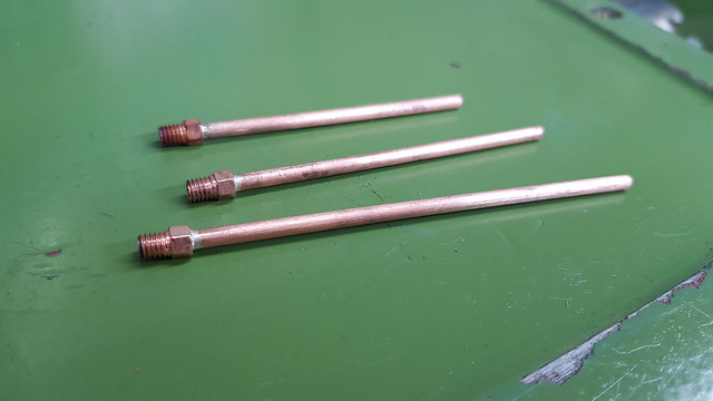 20200328_213932 20200328_213932 by The train Man, on Flickr |
|
|
|
Post by andyhigham on Mar 28, 2020 23:47:17 GMT
|
|
|
|
Post by Roger on Mar 29, 2020 8:20:27 GMT
This is the oil pot on Chattox. one each side feeds axle boxes and valve spindle The dodgy screw in the reach rod is just stopping it dropping down while I am working on the cab Hi Andy, That's a neat arrangement. I presume you have pretty small copper pipes for each of the feeds, and wicks to regulate the flow? 1501 doesn't appear to have any such arrangement, although in fairness you wouldn't see a box unless you crouched down low enough to see it. I could certainly have done it that way, and it would probably have been the only sensible arrangement if there was just a drilled hole in the eccentrics that didn't hold much oil. As it is, they hold enough oil to last a running session, as does the one for the feed pump, so I don't need a regulated supply from a header tank to keep them lubricated. |
|
|
|
Post by keith1500 on Mar 29, 2020 18:04:55 GMT
...just thought.... most locos have sandboxes which are included as part of the detailing. How about making the sandbox into a discrete oil box / reservoir with the pipes hidden from view.
|
|
|
|
Post by Roger on Mar 29, 2020 19:56:56 GMT
...just thought.... most locos have sandboxes which are included as part of the detailing. How about making the sandbox into a discrete oil box / reservoir with the pipes hidden from view. Hi Keith, I had exactly the same thought, but decided against it because you really need wicks if you have a reservoir. The front sandboxes are tucked away on the inside with a small opening, so I didn't think that would work very well. |
|
|
|
Post by Roger on Apr 3, 2020 20:06:56 GMT
The front of the smokebox saddle on SPEEDY doesn't go down as far as the top of the buffer, so there needs to be some sort of infill piece there. You can see from this photo that there's strangely shaped cover plate that bolts onto the face of the casting, missing two cast in pipes from the cylinder exhausts.  IMG_1396 IMG_1396 by The train Man, on Flickr Ideally I'd like to copy that exactly, but it's simply not possible because the frames are the wrong shape, and the cylinders are too low. That means the whole arrangement can't be made to look right, whatever you do. There's no fix for it, so I've decided to just make a feature that's in the style of what's there, and put up with the fact that it's not right. There's another issue, and that's the top front fixing bolt for the cylinders which get in the way. I've had to make the curved infill oversize so that it covers the bolt, and hopefully allows it to be undone and removed. It's really close to the inside of the curved piece, so that's going to have to be made hollow. Anyway, below is the best I can do with where I am. It just goes to show how different SPEEDY is to 1501.  Infill parts Infill parts by The train Man, on Flickr Here's the same model, but with the separate pieces in different colours so you can see how that's built up. At the moment I don't know if this can be permanently attached along with the smokebox saddle, or whether it's going to have to be removable. If it's removable, I'll have to make sure it's going to slide in and out after it's all been painted.  Coloured infill parts Coloured infill parts by The train Man, on Flickr Anyway, here's the Yellow part being machined with a 16mm Rippertaking 2.5mm deep cuts on the profile. Being Free Cutting Mild Steel Bar, it makes short work of it with a sharp cutter, and pretty quietly too.  20200403_143544 20200403_143544 by The train Man, on Flickr The 3D shape of the curved portion was roughed out at the same time  20200403_160815 20200403_160815 by The train Man, on Flickr I'd actually made a mistake by not telling the CAM operation to 'clear flats', and that left a big step to clean up in the next operation which was a bit noisy. I've changed that for the next one.  20200403_165616 20200403_165616 by The train Man, on Flickr The 16mm indexable mill has polished inserts for Aluminiun which I find to be much quieter than the relatively blunt general purpose ones it came with. I've shortened this cutter and relieved the shank to provide more clearance on deep cuts. Here, I'm setting the zero for the tool to the top of the stock.  20200403_165804 20200403_165804 by The train Man, on Flickr The flat sides and the 3D machining were all done with this tool since it has a handy corner radius for getting a decent finish and for leaving the blend radius.  20200403_200410 20200403_200410 by The train Man, on Flickr This will clean up nicely with very little effort. The other part is machined using the same program, but my utility program has a function to mirror it in the X-axis, so I do that for all of the tool paths and save them as X-Mirrored named versions so I don't get confused! 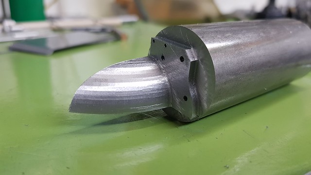 20200403_202641 20200403_202641 by The train Man, on Flickr |
|
|
|
Post by 92220 on Apr 4, 2020 9:23:04 GMT
NICE ONE Roger!! It's great to see someone making the effort to put small, non-working detail like this on their loco. Your loco is a real work of art!!
Bob.
|
|
|
|
Post by Roger on Apr 4, 2020 21:22:22 GMT
This is the second of the two infills below the smokebox saddle...  20200404_115126 20200404_115126 by The train Man, on Flickr ... and now I've switched from the 4-jaw to the tilting rotary table to do the inside. You'll notice that I didn't do it all in this chuck, and that's because it's not that rigid and it would have take much too long. So here I'm using the wobbler against the face since it's not feasible to use it on the end. I know the distance from the end in the 3D model, so after setting this to X-3.5 which is the ball radius, I drove it to X-28 and then zeroed the DRO.  20200404_122609 20200404_122609 by The train Man, on Flickr And here's a quick sanity check at X0Y0 to make sure it's plausible.  20200404_122525 20200404_122525 by The train Man, on Flickr The inside was roughed out with 0.5mm deep cuts using an 8mm cutter.  20200404_133757 20200404_133757 by The train Man, on Flickr The inside was finished with a 6mm ball nosed cutter taking off 0.2mm with a 0.1mm step over.  20200404_141255 20200404_141255 by The train Man, on Flickr The two 1mm holes for the location pins for the gusset were then added.  20200404_145838 20200404_145838 by The train Man, on Flickr Then it was a simple matter of parting it off.  20200404_151611 20200404_151611 by The train Man, on Flickr It's surprising how much finishing the radius took. The problem is that the 3D model uses triangular facets, and when it's shiny, you can see them.  20200404_154658 20200404_154658 by The train Man, on Flickr 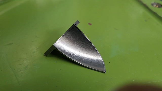 20200404_154713 20200404_154713 by The train Man, on Flickr Anyway, that's both of those done.  20200404_221713 20200404_221713 by The train Man, on Flickr |
|
|
|
Post by springcrocus on Apr 4, 2020 21:48:28 GMT
Not often I commend CNC work but those components are particularly noteworthy. Cracking job, especially when one remembers that this is not an industrial machine with Fanuc or Heidenhain controllers.
Regards, Steve
|
|
|
|
Post by Roger on Apr 5, 2020 20:23:46 GMT
This is one of the backs of the inflll pieces below the Smokebox Saddle..  20200405_111031 20200405_111031 by The train Man, on Flickr ... and turning the stock round there was just enough room for the other one. This is 5mm Cold Rolled Mild Steel bar macihned with a 2mm cutter and 0.5mm deep cuts. 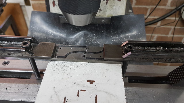 20200405_133608 20200405_133608 by The train Man, on Flickr And this is the curved cover plate that fits on the front of the Smokebox Saddle.  20200405_135854 20200405_135854 by The train Man, on Flickr  20200405_153500 20200405_153500 by The train Man, on Flickr This is the plate than sits on top of and behind the buffer. 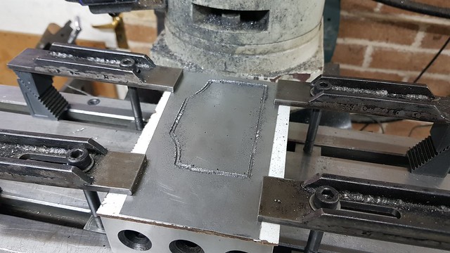 20200405_181125 20200405_181125 by The train Man, on Flickr This is going to be the lamp bracket that's welded onto that last plate. Actually I'll rivet it on and file the rivets flush. I'm drilling the inside corner of the bracket 1.2mm to give the 1mm cutter an easier time when I finish it.  20200405_183912 20200405_183912 by The train Man, on Flickr The roughing cut was done with a 2mm cutter which won't get into the corner.  20200405_191137 20200405_191137 by The train Man, on Flickr However, the 1mm cutter will, and that can profile at 50mm/min at 0.1mm depth of cut using the high speed spindle at 15000RPM I'm using a Carbide PCB burr intended for machining Glass Fibre, which is totally unsuitable for this sort of thing, but it works. The great thing about these is that they are very cheap, about £1, and they are long. This cut it 6mm deep, so a proper cutter for this would be really expensive.  20200405_201016 20200405_201016 by The train Man, on Flickr 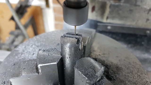 20200405_192014 20200405_192014 by The train Man, on Flickr The pins are just short lengths of 1mm Silver Steel.  20200405_194947 20200405_194947 by The train Man, on Flickr  20200405_200926 20200405_200926 by The train Man, on Flickr It's a bit hopeful that they would all line up, and I'll have to make another gusset with the holes in a slightly offset position for the one on the left.  20200405_204517 20200405_204517 by The train Man, on Flickr Anyway, they're nearly ready for Silver Soldering. I had originally intended these to go on a one piece back, but then realised that this wasn't necessary since the middle was covered by that curved plate on the front. The idea now is to use slotted holed on the rear fixing so that the sides can be pulled up onto the painted frames and then locked off. There will be bolts holding both these and the ones on the outside of the frames. |
|
JonL
Elder Statesman
 WWSME (Wiltshire)
Posts: 2,906
|
Post by JonL on Apr 6, 2020 18:36:23 GMT
This is pretty much finished now isn't it?!
|
|
|
|
Post by Roger on Apr 6, 2020 20:32:32 GMT
This is the last of the lamp brackets, there are three this hand and one the other way round. I'll add the fixing holes in those shortly.  20200406_110253 20200406_110253 by The train Man, on Flickr I'm using plenty of Silver Solder on this assembly to give decent sized fillets on what ought to be a casting. The Florist's wire is there to stop the end from lifting when it gets hot.  20200406_191800 20200406_191800 by The train Man, on Flickr  20200406_192104 20200406_192104 by The train Man, on Flickr I had to re-heat this one, it didn't take all the way along.  20200406_193519 20200406_193519 by The train Man, on Flickr Both of them ended up with the Florist's wire Silver Soldered on. That's because it wasn't possible to heat the 5mm thick plate up without also getting everything else too hot. I should have supported them so that I could heat the undeneath really, then that wouldn't have happened.  20200406_195925 20200406_195925 by The train Man, on Flickr Anyway, they've cleaned up nicely. There's still a bit more to do, but they're pretty much done. 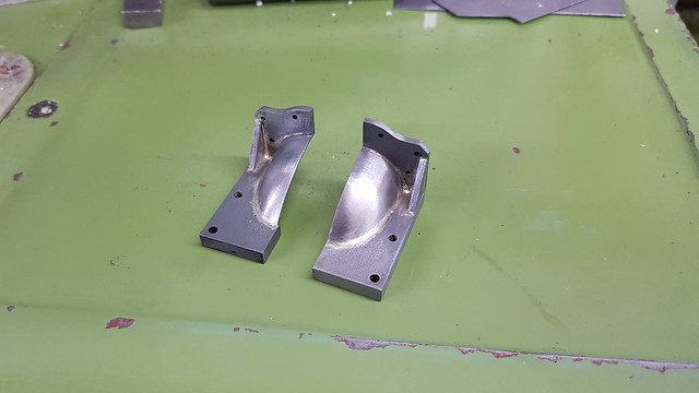 20200406_212151 20200406_212151 by The train Man, on Flickr I also machined the 2mm thick support plate that will hold these onto the back of the Smokebox Saddle.  20200406_212234 20200406_212234 by The train Man, on Flickr |
|
|
|
Post by coniston on Apr 6, 2020 22:25:02 GMT
Very nice work as usual Roger, just a thought as so much of your work is CNC you could always sell kits to build these later? (he says tongue firmly in cheek)
I'm sure I've said it before but your methods although for CNC do offer some alternatives worth considering even on manual machines, for that I thank you.
Chris D
|
|
|
|
Post by Roger on Apr 6, 2020 22:43:54 GMT
Very nice work as usual Roger, just a thought as so much of your work is CNC you could always sell kits to build these later? (he says tongue firmly in cheek) I'm sure I've said it before but your methods although for CNC do offer some alternatives worth considering even on manual machines, for that I thank you. Chris D Thanks for that Chris. I agree that now many folk have milling machines with linear scales, you can certainly use some of these techniques for machining right around a rectangular plate like the one shown here for example. You can easily work out the centre coordinates for the corners and leave an additional amount for roughing, just like it's done in CNC. There's another thread about MNC, or Manual Numerical Control, whereby you can output the coordinates using the CAM output from something like Fusion 360 so you don't even have to work them out. Ok, it's long winded for a difficult profile, but it is possible. You can also use a single reference, say the middle, and do all of the operations relative to that. CAD can help find the relevant coordinates. Lots of possibilities when you can position accurately without backlash being an issue. |
|
|
|
Post by delaplume on Apr 7, 2020 4:02:16 GMT
Hi Roger,
Great stuff as usual.....I'll try and give some of it a go ...
Have you checked your "Posts" lately ??........11,478 !!.......That must be a Forum record ??.........Where do you find the time ??
Looks like we'll have to wait a while longer before we can see 1501 in action but I'm sure it'll be worth it...
Thanks for including those detail photos about silver soldering....I've never really mastered that one ( Gas, Arc, Mig and Soft soldering are OK ) ..Can you just remind us what solder, flux etc you are using please..
Joyce and I send our regards
|
|
|
|
Post by Roger on Apr 7, 2020 5:18:14 GMT
Hi Roger, Great stuff as usual.....I'll try and give some of it a go ... Have you checked your "Posts" lately ??........11,478 !!.......That must be a Forum record ??.........Where do you find the time ?? Looks like we'll have to wait a while longer before we can see 1501 in action but I'm sure it'll be worth it... Thanks for including those detail photos about silver soldering....I've never really mastered that one ( Gas, Arc, Mig and Soft soldering are OK ) ..Can you just remind us what solder, flux etc you are using please.. Joyce and I send our regards Hi Alan, Yeah, it's a mightly long thread. I'm surprised anyone is still looking! There's still an awful lot to do, the cylinder cladding, injectors, more cab details. The list never ends, even though it's definitely shorter. There's nothing special about the Silver Solder or Flux I use, it's just the normal low temperature varieties of both. The trick is to cover everything in loads of flux, lay the Silver Solder into the joints and keep prodding it if it wants to stray away, and heat it mostly away from the joint or underneath. The key with this approach is that you don't have to get it anywhere near as hot to melt the Silver Solder, the molten flux transfers the heat to the Silver Solder so it melts the moment it's hot enough. I know most people don't do it that way, but it works for me. |
|
|
|
Post by delaplume on Apr 7, 2020 7:51:32 GMT
Quote}--- "I know most people don't do it that way, but it works for me."...... certainly does, the photos prove it and that's the way I'll be doing it in future...
I'll be closing my BOC Oxy-Actylene account soon ( an expensive left-over from Self-Employment days ) and just using a Propane gun for general heating....What size burner is suitable for general use would you say ??
|
|
|
|
Post by 92220 on Apr 7, 2020 8:20:32 GMT
Hi Alan.
It's strange how we all use different methods of working to achieve the same ends. You are intending giving up your BOC Oxy account, and use a propane torch. I also have both, and almost always use oxy-propane for my silversoldering. It allows me to do progressive soldering on complicated thin (down to 0.6mm) sheet steel fabrications...even enabling me to add pieces to the fabrication, within 1/2" of an already finished joint. Rarely do I have a problem with distortion either, on the smaller jobs. Larger jobs I just make up jigging to hold everything rigid 'till cold.
On a totally different note, and nothing to do with Roger's superb thread.....sorry to add the following note Roger....I don't know if others have found this....when I type anything on the forum, I often use words that are common to our hobby, like Silversoldering, in the lines above. That word comes up underlined in red. I accidentally right-clicked the mouse while the cursor was over the underlined word. I found it's a spell-checker, and then clicking on the suggested word that suits, alters what was originally typed...just like any other spell-checker.
Bob.
|
|


