|
|
Post by coniston on Sept 10, 2020 19:18:05 GMT
Coming on nicely Roger, just a thought, you might find news paper easier to use for masking than note paper, generally being that much thinner it is easier to keep in place.
Chris D
|
|
|
|
Post by delaplume on Sept 10, 2020 21:02:06 GMT
Coming on nicely Roger, just a thought, you might find news paper easier to use for masking than note paper, generally being that much thinner it is easier to keep in place. Chris D Yes, I'd agree with that............my local Council delivers a "freebie" newspaper every Thursday and what a blessing that is !!...............Recently I had to spray the cab roof of a Simplex loco and given the large area the newspaper covers I had the whole loco covered in about 20 mins. or so.... |
|
|
|
Post by Roger on Sept 10, 2020 21:31:44 GMT
Coming on nicely Roger, just a thought, you might find news paper easier to use for masking than note paper, generally being that much thinner it is easier to keep in place. Chris D Sadly I don't get a newspaper, not even a free one here. |
|
|
|
Post by Roger on Sept 11, 2020 18:08:53 GMT
I've sprayed a second coat of Red paint to the inside of the frames, so hopefully I can move on when that's dry. It's not the best of finished, but it's probably good enough. The drive belt for the 4th Axis finally arrived today, and although the tooth form I machined was great, there was something very wrong with the pitch. Anyway, I can see why that was wrong now, so I've changed it on the model and I'm making a new one. However, before doing that, I thought I'd quickly 3D print a small ring of the same toothed pulley profile, and this looks spot on. This is what I should have done in the first place!  20200911_161940 20200911_161940 by Roger Froud, on Flickr |
|
|
|
Post by 92220 on Sept 11, 2020 18:26:33 GMT
Hi Roger.
That looks good! Having 3D CAD and the 3D printer sounds the right way to go. It will be very interesting to see when you have it all finished and working.
Bob.
|
|
|
|
Post by andyhigham on Sept 11, 2020 19:28:57 GMT
I'd probably be tempted to 3D print the pulley and fit it.
|
|
|
|
Post by doubletop on Sept 11, 2020 20:39:12 GMT
I'd probably be tempted to 3D print the pulley and fit it. That crossed my mind as well. With that number of teeth in contact with the belt the load on each tooth shouldn't be that great. Pete |
|
|
|
Post by jon38r80 on Sept 11, 2020 21:30:50 GMT
£3d print the outer toothed bit to fit over a core machined from that nice Aluminium pulley you already have would seem to me to be a way to go. The 3D bit could always have some lugs to fit keyways on the outside of the pulley.It seems a shame to me to waste all the work and metal that went into the Aluminium one.
|
|
|
|
Post by Roger on Sept 11, 2020 21:39:14 GMT
I did consider printing the whole pulley to assist in making the new one, but thought better of it. Relying on the accuracy of a cheap 3D printer to then create a precision product isn't really sensible. I've almost finished the blank for the new one, and I've found a way to use the High Speed Spindle to maching this one more quickly. Hopefully I'll get that done tomorrow.
|
|
|
|
Post by Roger on Sept 12, 2020 11:54:37 GMT
Seconds out, Round two!  20200911_195448 20200911_195448 by Roger Froud, on Flickr This time I'll do the teeth first before adding the other holes in the face of it. This is the tiny wobbler I made for use with the High Speed Spindle. 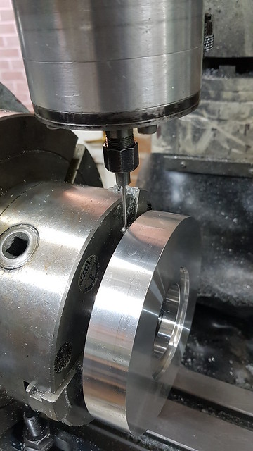 20200912_084312 20200912_084312 by Roger Froud, on Flickr I've never used it like this before, mainly because the spindle is too close to the front of the bed to be of much use. However, for this situation where I only need to be able to reach the centre line of the rotary table, plus or minus a few millimeters, it's fine.  20200912_084318 20200912_084318 by Roger Froud, on Flickr Anyway, here's a wobbly video of one tooth being cut. The video starts just as it takes the first cut. You can see that the first X/Y pass is slightly slower than the rest in each of the two parallel roughing passes. This is a feature you can use in Alibre CAM, you just select a percentage value of the feed being used for the main cut. It just gives it an easier time before it starts cutting on one side of the cutter on subsequent passes. I stopped filiming before finishing the whole of the final pass, you get the idea though. Each tooth is taking under three minutes which is fine. It's almost twice as quick as doing it with the main spindle and a lot quieter. This is running at 12,000RPM and 120mm/min so it's not crazy fast. However, I'd rather be patient and get the job done without breaking cutters and going deaf. I could potentially run at twice these figures, but would also give the machine a really hard time doing 1000mm/min on the finishing pass. I'd almost certainly have to drop that speed down anyway.  20200912_105349 20200912_105349 by Roger Froud, on Flickr This is how that tooth looked at the end.  20200912_110005 20200912_110005 by Roger Froud, on Flickr |
|
|
|
Post by Roger on Sept 12, 2020 20:24:12 GMT
|
|
|
|
Post by Roger on Sept 12, 2020 22:56:47 GMT
The connections for the 4th axis servo motor pose a bit of a problem. Clearly these servos are intended to be permanently connected and sleeved or put in conduit or trunking. I suppose they're saving money, but it would be much nicer to have a decent metal one piece connector with all the wires in. Now, I could do that myself, but I'd rather not change them because then I can't swap them around if I'm ever fault finding. The whole 4th axis is going to be moving around, so some sort of decent termination with strain relief is going to be necessary. So I've 3D printed a box that bolts to the 4th axis servo mount which has pockets that locate the connectors. I've also designed a mating arrangement that holds the two connectors on the other half. There's going to be a 28mm plastic conduit coming from the control box, so I've included a female mount for that too. I couldn't see why the conduit just wouldn't fit properly. I made two versions and neither of them worked. Finally the penny dropped. I'd looked at the conduit and thought it was a spiral pattern like the vacuum hoses that I'd made adaptors for. It turns out that it's a concertina pattern! Doh!  20200912_204655 20200912_204655 by Roger Froud, on Flickr I've embedded M3 hex nuts in the bottom half to secure the lid. Those were inserted by adding a pause to the print, dropping them in place, then resuming the print. That works really well. So the plastic conduit is missing from these photos because I'm printing out a third attempt which has the right pattern to engage with it. Yes I know it's a bit clunky, but it's a robust solution that does what I need. The two halves of the RH connector are held together with M2 cap screws that tighten into M2 square nuts that are slid into pockets from the side.  20200912_205339 20200912_205339 by Roger Froud, on Flickr There are two M3 square nuts trapped between the two halves of the box. The RH connector has two 3mm holes that will be used to secure the connector firmly to the box so the connectors done work their way out. The power connector has locking ears but the signal connector doesn't. I've made the RH housing so that it depresses the power connector locking ears so they don't work. Getting to them to release them would be difficult, and holding the whole arrangement together with them wouldn't be satisfactory. Anyway, it's almost done, so I just have to add the fixing holes to the servo mount so can try it out. I've made those on a square pattern so that the box can be fitted either way around and also facing to the front. That's so the 4th axis can be used on either end of the table with the Servo drive moved to the front. Having the conduit facing away from the control box isn't going to work, it's not long enough for that and it would get in the way.  20200912_205356 20200912_205356 by Roger Froud, on Flickr |
|
|
|
Post by doubletop on Sept 13, 2020 2:53:26 GMT
|
|
|
|
Post by Roger on Sept 13, 2020 11:04:02 GMT
Thanks for that. I'd need more than 8 ways though. Canon do a lot of military spec connectors that would do the job. I'd prefer to keep the ones already fitted for preference though. |
|
|
|
Post by Roger on Sept 14, 2020 22:57:07 GMT
Good progress on the 4th axis today. This is the taper lock style of compact coupling for attaching the 25 tooth pulley to the 19mm Servo Motor shaft.  20200914_110916 20200914_110916 by Roger Froud, on Flickr I set up the compound slide using the Diameter DRO to tell me how long the Opposite side of the Right Angled triangle is when I move the compound slide 30mm First I touch the tool against the side of the chuck...  20200914_112356 20200914_112356 by Roger Froud, on Flickr ... set the DRO to zero...  20200914_112417 20200914_112417 by Roger Froud, on Flickr ... then clear the tool away and move the compound slide 30mm, returning the tool to just touch the chuck again.  20200914_112458 20200914_112458 by Roger Froud, on Flickr The reading is twice the Opposite side of the triangle. I've got a simple 3D model I use for giving me this figure. I just adjust the compound slide and repeat the process in either direction until it's close enough. Simple but effective.  20200914_112501 20200914_112501 by Roger Froud, on Flickr  20200914_114956 20200914_114956 by Roger Froud, on Flickr I need to hold the 25 tooth pulley so I can bore out the taper to suit... 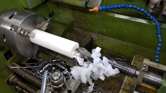 20200914_120547 20200914_120547 by Roger Froud, on Flickr ... and this split sleeve is an easy way to do that.  20200914_121745 20200914_121745 by Roger Froud, on Flickr The boss needs to come off and the taper made to the same angle as the split sleeve. The easiest way to do that is to turn the tool upside down and turn the back surface. 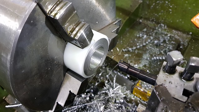 20200914_124124 20200914_124124 by Roger Froud, on Flickr Ckamping it all together makes drilling and tapping the holes easier since I can do it all in one setup.  20200914_125517 20200914_125517 by Roger Froud, on Flickr  20200914_145118 20200914_145118 by Roger Froud, on Flickr Finally the sleeve was slit using a 1mm slitting saw, climb milling. That's something you can do on a machine without backlash, I wouldn't risk it on a conventional machine. The feedrate was 5mm/min, much slower than you can realistically set most power feeds.  20200914_153238 20200914_153238 by Roger Froud, on Flickr Anyway, that fits like a glove, so I'm really pleased with that.  20200914_180503 20200914_180503 by Roger Froud, on Flickr Because I'd calculated the diameter of the 90 tooth pulley incorrectly, the belt was too short. I can do away with the rollers and just use the needle rollers directly if I shorten the mounting plate by 2mm.  20200914_201013 20200914_201013 by Roger Froud, on Flickr I've added two M3 tapped holes to the motor spacer, so now the connector box can go on.  20200914_225752 20200914_225752 by Roger Froud, on Flickr I've made some spacers to place the needle roller bearings slightly apart, and larger diameter ones to guide the belt.  20200914_225758 20200914_225758 by Roger Froud, on Flickr The 3D printed guard fits like a glove too. I've made a large hole in the middle to take different inserts depending on what chuck is fitted. The guard is too big to print in one piece, so I've cut it in half and added some slots for M3 square nuts so I can bolt the two sides together.  20200914_231759 20200914_231759 by Roger Froud, on Flickr A quick sanity check to make sure that I've got the Servo motor far away from the quill to miss it when the table moves right to the back.  20200914_231915 20200914_231915 by Roger Froud, on Flickr So far so good. I need to sort out the other half of the belt guard and various blanking plugs to keep the swarf out. I also need to sort out the conduit connection to the control cabinet and the wiring for the DC Brake and Step & Direction signals for the Servo Amplifier. This is all way better than I'd conceived of doing it before, it's so much more robust and flexible than some of the other ideas I explored. This is going to get a lot of use. 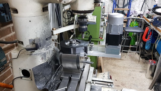 20200914_232111 20200914_232111 by Roger Froud, on Flickr |
|
dscott
Elder Statesman

Posts: 2,437
|
Post by dscott on Sept 15, 2020 0:32:49 GMT
I have been won over on the Taper Lock pulleys and have used them on the Contraption we are currently bombing round the track on or behind. Saturdays outing was EVENTFUL with 2 derailments and a loose connection for 2 laps when we were down to one motor.
All the point-work was rusted up and an hour later they were ALMOST working. Masses of weeds to pull as well.
Friend Ray described the coming off on the points "As a Train Wreck!" Just had to laugh.
Lovely work as always Roger. I Love the belt tensioners.
Your last photo could be a lovely Quiz What is missing? Just to keep us on our toes.
The Rapid Prototyping machine is becoming such a useful piece of kit.
Yes I have a scattering of parts for one in the Queue.
The Month in Plymouth has put me back, on the workshop extension/mass storage while the garage and house get insulated.
Always something to do.
David and Lily.
|
|
|
|
Post by Roger on Sept 16, 2020 23:01:32 GMT
I managed to finish the wiring on the 4th Axis control, that's the RH one in the cabinet. It's simple enough, just the power connections, 4 wires for the optically coupled Step & Direction connections and the enable. There's also the DC brake which I've piggy backed off the one on the Z-axis since all of the servos are enabled as a block. The error code is complaining that the drive is missing, which is not altogether surprising since it's not connected!  20200916_230403 20200916_230403 by Roger Froud, on Flickr I started tuning the drive but the belt wasn't tight enough, so here's a little plate...  20200916_230322 20200916_230322 by Roger Froud, on Flickr ... that goes here to pull the motor so it's nice and tight.  20200916_232846 20200916_232846 by Roger Froud, on Flickr Tuning it is quite challenging because I need the Servo to be as stiff as possible. Achieving that without instability and oscillation is far from easy, but I'm homing in on it. The drive definitely gives the right output ie a command of A360 drives the big pulley one complete turn. I think the direction might be wrong though, I'll have to check and possibly reverse that. So I'm almost at a point where I can use it, so long as the 3D printer successfully makes the rest of the guard parts overnight. |
|
|
|
Post by Roger on Sept 17, 2020 21:41:16 GMT
This is the inside of the belt guard showing the M3 square nuts in place for attaching the other half...  20200917_154202 20200917_154202 by Roger Froud, on Flickr ... like this. It's not massively strong but it doesn't have to be. 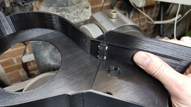 20200917_154851 20200917_154851 by Roger Froud, on Flickr The position of the holes that clear the idler set screws is 1mm out, so I can't fit the little covers until the new one finishes printing. The RH end of the guard had a gap where the motor had to move to adjust the tension. The piece on the RH end of the guard slides along to cover that and also doubles up as a clip to hold the guard in place too. 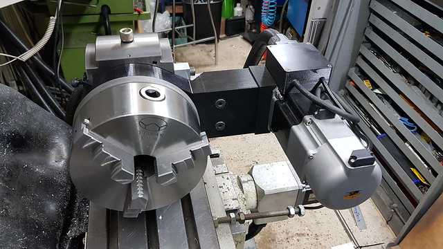 20200917_202019 20200917_202019 by Roger Froud, on Flickr I didn't make the clip part quite long enough to get a secure grip on the aluminium support, so I'm printing out another one of those too. I've refitted the locking handle in case I want to use that.  20200917_202058 20200917_202058 by Roger Froud, on Flickr I've also made a blanking plug on the bottom where the worm drive went so I can keep the swarf out.  20200917_204045 20200917_204045 by Roger Froud, on Flickr The same thing goes for the hole that had the lever to move the indexing pin in and out. The hole is a blind one in case I need to screw a bolt in there to pull it out. The M12 cap screw just fills the hole that's used for the lifting eye. You can see how little room there is behing the chuck. I had to swap the cap screws for Hex bolts to get it to fit.  20200917_204100 20200917_204100 by Roger Froud, on Flickr I've spend a couple of hours exploring all of the Servo tuning options, and have got it about as tight as I can without it really complaining. Anyway, here's a wobbly video of it in motion.  20200917_221205 20200917_221205 by Roger Froud, on Flickr The jogging seems to work fine on 1 and 0.1 degree increments, but for some reason it ignores the 0.01 resolution setting which is what I need for clocking up. It does work if you command it from the command line, so I have no idea why it won't behave. Anyway, I've written a post to the Mach4 Forum in the hope that someone will pick it up and put me on the right lines. Mach4 is a very clever piece of software, but it still has a lot of bugs which surface when you try to customise things. The team are pretty good at sorting out the ones that are badly wrong, not so good when it only affects one or two users. |
|
|
|
Post by Roger on Sept 18, 2020 21:54:51 GMT
The new guard parts have been printed and fitted, so this is finally ready for use. Having said that, I'd like to fit two adjustable stops so that I can quickly set it horizontally and vertially without clocking it every time, or at least get it ready for a quick check. More on that later. My CAM software won't generate any 4th axis moves, and for the most part that's really not a problem for the things I want it to do. However that leaves the issue of creating programs for operations that need to be repeated at a variety of angles. The most obvious one would be to automate gear cutting, something that would have been very handy for cutting the 90 tooth pulley! So here's a video of a crude simulation of the sort of program that would be required to machine a simple tooth with a single cut. It's not intended to be sensible moves in the X-axis, just to show the way those moves interleave with each new angle.  20200918_223713 20200918_223713 by Roger Froud, on Flickr And this is how that was done... M90 (absolute positioning mode so we don't end up leaving it in incremental mode!) M3S100 A0 (First absolute angle) M98 P1234 L90 (Repeat subprogram 1234 L times) M5M30 O1234 (Sub program to cut one tooth and increment angle) (Start of one tooth) G1X0F500 X5 (End of one tooth) G91 (incremental positioning mode) A4F1000 (increment angle to next tooth) G90 (absolute positioning mode) M99 So this is pretty simple. I can have a complex program for one tooth or say to face off one side of a hexagon, and then add the first part of this in front of it, and the incremental move of the A-axis on the end. Obviously it needs a little care to make sure it doesn't go pear shaped, but it's not too painful. Here's a link to the full G-Code list available for Mach4 |
|
|
|
Post by Roger on Sept 20, 2020 10:48:38 GMT
A bit more progress on painting the chassis today. I sprayed the inside black last night, and here it is turning on the spit with the dust cover draped over it. I left it turning for about 30 minutes, the paint looked pretty wet and it's not that thick.  20200919_202205 20200919_202205 by Roger Froud, on Flickr Anyway, it's come out good enough although it's far from perfect.  20200920_110748 20200920_110748 by Roger Froud, on Flickr IF you get it in the light, it doesn't look that great, but it will do.  20200920_112421 20200920_112421 by Roger Froud, on Flickr  20200920_112426 20200920_112426 by Roger Froud, on Flickr  20200920_112441 20200920_112441 by Roger Froud, on Flickr Now the more tricky part looms closer, the parts that show more. I'll leave it for a week to go off hard enough to mask up again and then tackle the black outside. I've made this a lot easier by doing the brackets and inside separately. It's much easier to spray that front area without the bolt head for the Smokebox Saddle getting in the way too. It's taken a lot longer to do it this way, but I think the result will be better for it.  20200920_112604 20200920_112604 by Roger Froud, on Flickr |
|


