oldnorton
Statesman
 5" gauge LMS enthusiast
Posts: 693
|
Post by oldnorton on Oct 2, 2020 8:49:47 GMT
As well as bolt head seatings, an interesting thought arises about whether to paint the inside of faces that are going to stay bolted together for ever (but not faces with a load issue like stretchers, and cylinder block mounts that must surely remain unpainted). I had the same quandary yesterday bolting together side platforms with jointing plates under and through nuts and bolts. They are in steel, and not brass. When they are painted later, and the paint cracks in use, water might/will penetrate and the joint will rust. My saving thought is that the engine will always be oiled, and WD sprayed, when working, so the first paint cracks will hopefully admit oil and not water. Perhaps I should dismantle them later and at least use a primer? How do I avoid becoming a worrier and perfectionist  |
|
|
|
Post by Roger on Oct 2, 2020 8:58:20 GMT
As well as bolt head seatings, an interesting thought arises about whether to paint the inside of faces that are going to stay bolted together for ever (but not faces with a load issue like stretchers, and cylinder block mounts that must surely remain unpainted). I had the same quandary yesterday bolting together side platforms with jointing plates under and through nuts and bolts. They are in steel, and not brass. When they are painted later, and the paint cracks in use, water might/will penetrate and the joint will rust. My saving thought is that the engine will always be oiled, and WD sprayed, when working, so the first paint cracks will hopefully admit oil and not water. Perhaps I should dismantle them later and at least use a primer? How do I avoid becoming a worrier and perfectionist To be honest there are no good answers to any of these questions, just compromises. I've left bare metal on the smokebox saddle, gear frame and stretchers as well as the cylinders for the reasons you mention. However, that's bound to look a little more ragged around the edges where the paint ends. Hopefully that won't be a huge issue, since the cylinders will have cladding to cover the joints, and the stretchers are inside. The only one that might show on mine is the front of the smokebox saddle where it meets the frame. That might need a little careful work with a tiny brush, right in the corner. We'll see. I'm going to apply Fertan to all of the bare metal parts before bolting up tight. I think that's as good a strategy as any. |
|
timb
Statesman
Posts: 512 
|
Post by timb on Oct 2, 2020 9:07:38 GMT
A bit late now Roger but if you were worried about rust etc you could have electroplated the frames with nickel before you started - quite cheap to do.
Takes paint well too!
Tim (late to the party as usual!)
|
|
|
|
Post by 92220 on Oct 2, 2020 12:13:35 GMT
Hi Roger.
I have a bath of 15% phosphoric acid into which everything steel goes, and it comes out with a rust proof iron phosphate coating. In actual fact, if you sand blast the steel on a damp day, and the steel flash-rusts in about a minute, when you phosphate it, the phosphate coating is really well adhered to the steel. That is how I protected the frames of my loco, back in the early 1970s. I alo have phosphated parts that have not been painted either, from around that time. Phosphoric acid is easy to buy in a 5 litre can off Ebay, and for it to be effective, it needs diluting to around the 15% mark. I also use the bath as a rust remover.
Bob.
Edit: The phosphate coating also make an excellent base for painting.
|
|
oldnorton
Statesman
5" gauge LMS enthusiast
Posts: 693
|
Post by oldnorton on Oct 2, 2020 13:04:58 GMT
I have a bath of 15% phosphoric acid into which everything steel goes... Brilliant !!! I just dunk the whole assembled item in phosphoric and it plates the hidden surfaces AND the inserted bolts! Just take care to dry it properly. Best idea I have heard for ages, and like all good ones is obvious really. |
|
|
|
Post by 92220 on Oct 2, 2020 13:32:46 GMT
Hi Oldnorton.
Not a good idea to dunk assembies in the phosphoric. It should always be wiped down thoroughly after dunking. Washing it off will tend to de-stable the coating before it has time to adhere to the steel. After wiping the excess phosphoric off, it will eventually dry and no more action will take place, but while in solution, like in between riveted/bolted plates, the acid will continue to work on the steel until it has been fully neutralised, and that might just loosen the joints. The phosphate coating is microscopic so won't add anything to the dimensions so just phosphate individual parts before riveting up. Hope that helps.
Bob.
|
|
oldnorton
Statesman
5" gauge LMS enthusiast
Posts: 693
|
Post by oldnorton on Oct 2, 2020 14:50:15 GMT
Not a good idea to dunk assemblies in the phosphoric. ruined my day ...  sorry, Roger for polluting your Thread, we will stop now. |
|
|
|
Post by Roger on Oct 2, 2020 21:58:50 GMT
Here are the 3D printed clamps in action, holding the two M10 studs to the bench, and a pail to hold it up at a sensible height.  20201002_161658 20201002_161658 by Roger Froud, on Flickr  20201002_161709 20201002_161709 by Roger Froud, on Flickr I had two goes at this, quickly wiping off the first coat which was too thick. I've got some lint free wipes to use for that, and some sponges too, both used in Nail Bars. Once wiped off with the appropriate thinners, I used low tack masking tape all over to make sure there was no dust. Anyway, here it is covered, waiting for inspection when it's dry enough.  20201002_224430 20201002_224430 by Roger Froud, on Flickr to be honest, I think the paint is on the thick side for spraying, even though it's 25% thinned. Unless you're generous with it, it simply doesn't form a continuous layer. From this angle it looks fine... 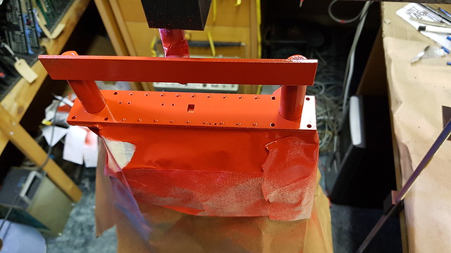 20201002_224519 20201002_224519 by Roger Froud, on Flickr ... but getting the light at the least complimentary angle, you can see the depressions around the rivets. I imagine the only way I'd avoid that is to have a thinner coat? As it happens, the finish is pretty good, so I'm inclined to live with it and just thin the paint a little more on the end I'm going to have to spend a long time looking at!  20201002_224531 20201002_224531 by Roger Froud, on Flickr |
|
|
|
Post by 92220 on Oct 3, 2020 8:16:08 GMT
Hi Roger.
All colours of paint can have a different viscosity depending on the pigments used. Vermilion, which is the basis of buffer beam red, is a semi transparent pigment. This means the manufacturer has to use more pigment to reach an acceptable covering power. This will make the paint thicker and so thinning the paint 25%, which is the general recommended amount, can be still too viscous. We have to bare in mind that we want a much finer finish, for our models, than is normally required.
Some colours, like buffer beam red, may need to be thinned more, but then more coats will have to be applied to get the required opacity. The main problem with this is that the gloss level will be slightly reduced due to the extra thinning, though most won't be concerned about this. By applying a number of thinner coats, you shouldn't get those rings around the bases of the rivet heads. Just as a point of interest, some of the top 00 gauge modellers, thin their paint 50% and apply up to 10 coats. However, it is difficult to end up with a gloss finish, though it can be done. You have to apply subsequent coats while the previous coat is still tacky, and play around with spraying distance from the surface. With the thinner paint you can also reduce the air pressure. It's quite a juggling act as it can end up with either a gloss paint ending up semi-gloss, or in the worst case, matt!!
Bob.
|
|
oldnorton
Statesman
5" gauge LMS enthusiast
Posts: 693
|
Post by oldnorton on Oct 3, 2020 8:40:08 GMT
To avoid the liquid rings forming around the rivets I would be inclined to make the early topcoats light and to land almost dry, i.e. gun further away, then the paint can't flow somewhere. Then add a final topcoat or two, before the earlier paint has dried, to give a wet gloss and partially wet the earlier layers to remove any dry stipple.
Norm
|
|
|
|
Post by Roger on Oct 3, 2020 11:22:12 GMT
Ok, thanks for those thoughts. I've got a couple of thin coats on which I'll leave to harden and then rub down. Unfortunately I've run out of Red paint, so I've just ordered some from Craftmaster which is the same price for twice the quantity compared to Phoenix Precision Paints. I'll see if I get on with that any better.
I thinned the paint a lot more, raised the pressure and stood back a lot more. It's going to be a struggle to get a full gloss finish whatever I do though, because you have to create a fully wet layer, and that's always going to pull in around the rivets.
The droplet size increases dramatially as you drop the air pressure, and that affects the way adjacent drops connect. You can certainly add as much paint with higher pressure thinner paint applied from a distance, but you still have to put down pretty much the same amount to get the dots to join up.
Anyway, I'll try it with the new paint when it arrives, and hopefully get it good enough. Painting has to be the most soul destroying part of Model Engineering. I can see why some people loath it.
|
|
|
|
Post by Roger on Oct 3, 2020 14:08:33 GMT
Ok, a change of plan. I've had a good look at this now it's dried a bit, and frankly it's going to take too much work to prepare that for another coat...  20201003_143245 20201003_143245 by Roger Froud, on Flickr .. so that's now gone. I did have less paint on it initially, but it was very granular and Matt. I think it would need to be even thinner to get it smooth. Anyway, I'll try again with the new paint and perhaps experiment with a different technique. I might try it really thin and see if I can get a light semi-gloss covering. I'll leave the front as it is. I might be able to carefully finish that by hand since it's got a fairly thick coat.  20201003_144137 20201003_144137 by Roger Froud, on Flickr |
|
|
|
Post by Roger on Oct 3, 2020 22:11:47 GMT
While I'm waiting for the Red paint to arrive, I'll get on with something that's a lot easier and predictable. This is the setup for making the injector body halves. I'm using the High Speed Spindle because the largest cutter I'm going to use is only 2.5mm diameter, and the finishing is going to be done with a 1mm Ball Nose. I can do it with the main spindle, but it takes too long.  20201003_225038 20201003_225038 by Roger Froud, on Flickr I've turned the OD so I can clock it up again if anything happens and the machine has to be shut down. Later that will be machined away, but it sometimes comes in useful and only takes seconds to do.  20201003_225043 20201003_225043 by Roger Froud, on Flickr The strategy is to maching this in the face of a piece of PB102 bar and then part it off so I can mount it the other way up to machine the outside. This is the combined roughing paths in one operation. It's all done with a 2mm cutter, 4mm long. It's not really deep enough, but the cutters are short. I'll probably rough to a greater depth with a larger cutter so there's less work to do from the other side. This is the only time I'll have a really good grip on the stock, so it will probably be best to do that. I'm only cutting 0.25mm deep on each cut so I ought to be able to ramp up the feedrate, we'll see. There are some pretty small features to get into, so I'll probably have to use a 1mm cutter to clean up the profile and give the cutter on the next operation an easier time. There's a lot to consider when machining this sort of thing. Tall vertical faces with restricted access are a big problem. Still, I've only got four halves to make in total, so I can take my time and plot a course through the necessary operations.  Rough inside Rough inside by Roger Froud, on Flickr |
|
JonL
Elder Statesman
 WWSME (Wiltshire)
Posts: 2,909
|
Post by JonL on Oct 4, 2020 10:02:39 GMT
Mounting the chuck on the mill bed like that looks so useful. I think I'll look at making an adaptor for one of my spare chucks. Of course an indexed holder would be even more useful... I really need to stop looking at this thread!
|
|
|
|
Post by Roger on Oct 4, 2020 10:39:26 GMT
Mounting the chuck on the mill bed like that looks so useful. I think I'll look at making an adaptor for one of my spare chucks. Of course an indexed holder would be even more useful... I really need to stop looking at this thread! Absolutely, it's so much easier to hold round (or hexagonal) things in a chuck. I've got this one and the large 4-jaw. The 4-jaw has bolt holes from the front that allows long Cap Screws to go into Tee nuts so that didn't need any modification. That seems to be quite a common feature, you might find that's the case on a 4-jaw you may have. A 4-jaw for one off work is fine since you're clocking to the outside of the part. For repeat work, obviously a 3-jaw is more convenient if that's accurate enough. |
|
|
|
Post by Roger on Oct 4, 2020 15:00:48 GMT
Continuing with the first attempt at an 8X injector body, here's a 2mm cut around the outside and a rough cut on the inside with a 2mm cutter.  20201004_095828 20201004_095828 by Roger Froud, on Flickr I tried a 2.5mm cutter, but decided I'd be better off with a 3mm cutter to go deep enough so it can be parted off when it's finished. Next time I'll do these operations the other way round. You can see that there are places where the 2mm cutter was too big to reach...  20201004_113031 20201004_113031 by Roger Froud, on Flickr ... so here I'm using a 1mm cutter to get into those places such as the back of the overflow flange.  20201004_114021 20201004_114021 by Roger Froud, on Flickr I've also created a path around the outside with the 1mm cutter to a depth of 2mm to get close to the finished profile. I've left 0.075mm all round. which you can just make out here. 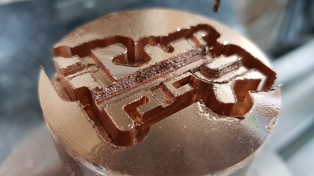 20201004_115818 20201004_115818 by Roger Froud, on Flickr The 0.8mm rivet holes are only 1.5mm deep, but the 1.4mm holes are 6.5mm deep so I can bolt it to the fixture while I spot face each of them down to leave about 1mm of the lug. A 1mm ball nosed cutter was used to machine the internal cavities.  20201004_151002 20201004_151002 by Roger Froud, on Flickr Here's a short clip of it being parted off with the lathe in the low belt setting to get enough torque.  20201004_151709 20201004_151709 by Roger Froud, on Flickr There are still quite a few burrs, but you always get that with Phosphor Bronze. The only concern I have at the moment is how thin the inlet water channel is. That's a wall thickness of about 0.5mm. I'll see how it goes and adjust that if it's not satisfactory.  20201004_153139 20201004_153139 by Roger Froud, on Flickr I don't realistically expect the first of these to be successful, although it might work out ok. The main thing is to get as close as possible in the first attempt and prove the method and dimensions are good enough.  20201004_153350 20201004_153350 by Roger Froud, on Flickr |
|
|
|
Post by Roger on Oct 4, 2020 16:09:17 GMT
I've just taken a look at the cone model and I'm going to need two reamers to make those, although I'll probably make a third shorter one for the steam cone while it's set up. Getting these as accurately made as possible is critical. The throat diameters depend on knowing that the angle is spot on, as do the position of the throats. Although the angles you use to design the injector don't have to be precisely 9 degrees for example, once you've designed it to use 9 degrees for the Mixing Cones, it's vital that this is what you actually make it to! A tiny error in the angle has huge consequences. Fortunately, I've modified the Jones & Shipman Tool and Cutter Grinder with a very accurate digital scale for setting the angle. I did that so I can grind collet tapers in the High Speed Spindles I occasionally repair. It's a magnetic tape type with 10micron resolution at a radius of about half a meter, so that's ideal for this job. I've ordered some 2mm diameter HSS drill blanks from Drill Service Horley to make these from. I thought I'd buy the smallest size that would fit the required taper so it's flexible and will follow the drill hole in the cone. The idea is that I'll know the diameter of the reamer at a known position along its length because I know it's 2mm at the intersection. Even if the flat isn't exactly to the drawing, I'll be able to measure where that is relative to the 2mm position. The only way to accurately get the cones to the drawing is to know exactly how far the reamer needs to be from the end. Relying on a diameter isn't going to be accurate enough.  Delivery cone reamer drawing Delivery cone reamer drawing by Roger Froud, on Flickr |
|
|
|
Post by Roger on Oct 4, 2020 18:17:42 GMT
A bit more on the injector design and construction... I think this is how the One Piece Cone is going to be for the first iteration. The diameters of the cross drilled holes have been chosen to match the gaps that would normally be between the cones if they were made separately. There are 6 of the larger ones and 8 of the smaller ones to get as large a volume as possible and to break the inside diameter all the way around. You can't add too many because it would be too weak. The idea is for this cartridge to be a reasonably close sliding fit in the bore. There's no need for the usual press fit which is normally requred to achieve accurate alignment and to seal one section from another. This design is only viable if I'm right about the overflow being able to share a single non-return valve. If I need to add a separate valve in the usual place, I'll have to think again. Personally, I think this is pretty easy to make compared to making three separate ones. The OD can be finished and then the two rows of cross holes can be done in one setup using the 4th axis. The bore can be drilled through at 0.5mm diameter and then reamed from each end. Obviously the overall length needs to be accurate and the distance the reamers are inserted is vital.  One piece cone drawing One piece cone drawing by Roger Froud, on Flickr |
|
|
|
Post by doubletop on Oct 4, 2020 19:57:09 GMT
.................... Painting has to be the most soul destroying part of Model Engineering. I can see why some people loath it. Painting is one of those phases of the different skills required to complete a model (frames, motion, boiler, platework, assembly and paint) any one of which can be the reason why a model never got finished. I never looked forward to painting until I got it to work to a reasonable degree. I've always painted the assembly rather than the separate components prior to assembly. We spend ages making parts to the correct sizes so adding a layer of paint between the faces somewhat negates the effort. Masking off the contact faces can be a pain and the source of problems later as there is no effective seal on the joint. To deal with the paint shadow around bolts and rivets I go round with a fine modelers brush and put a thin coat of paint on the heads and then spray while it is still wet. Although there are many ways of skinning cats ............. Pete |
|
|
|
Post by ettingtonliam on Oct 4, 2020 20:11:06 GMT
That reminds me that when we were erecting steel bridges, there was a requirement to give a 'stripe coat' of paint to bolt heads and plate edges before painting the main body of the steel work.
|
|


