|
|
Post by Roger on Oct 28, 2020 22:02:55 GMT
Hi Roger, Glad to see you living up to our original title ie}----- Society of Model and Experimental Engineers !! PS}-- I would suggest keeping the number of entries into the boiler shell down to a minimum........hence the use of a single manifold with various outlets for the suggestions above.........Also, why have you stipulated 2 safety valves ??....as a test boiler I can't see the need..... Keep at it....you'll soon be up to 13,000 posts which---if you calculate pro-rata--- means you'll have beaten Lewis Hamilton = Result !! Best wishes.. Alan Hi Alan, Oh yes, the fun is in doing new things. I've got a large M10 x 1 (fine) outlet at the top which can be either a single valve or a turret of some kind. It really doesn't matter. The two safety valves is belt and braces, but I thought it they were required for a locomotive for a good reason, then the same logic ought to be followed for a test boiler. I've kept the bulk of the fittings on the front because it's easier to machine all of those in one hit on the plate before it's welded on. The only thing on the back plate is the immersion heater, I wanted to make sure that didn't ever get wet, having mains voltage on it. |
|
|
|
Post by Roger on Oct 29, 2020 22:46:23 GMT
Sorry to be switching between different jobs, but that's just how they're coming along at the moment as time permits. Here I'm setting up for grinding the taper reamers for the injectors. The first thing to do is to set the axis of rotation of the chuck precisely parallel to the X-axis movement of the table so I've got a reference I can call zero degrees. To do that, I use a long piece of Brass and get it roughly set up and true with a few quick cuts, measuring the diameter at the extremes. Then I dress the wheel as in the picture so I know the face is also true to the X-axis.  20201029_220601 20201029_220601 by Roger Froud, on Flickr Then it's a matter of taking some really light cuts and checking the diameters. I've created a little spreadsheet that lets me enter the diameter at each end and the distance between them. That tells me the angle I need to move it and in what direction. With a couple of goes, I can get it pretty much spot on.  20201029_222149 20201029_222149 by Roger Froud, on Flickr So at that point I zero the angle on the digital scale.  20201029_222158 20201029_222158 by Roger Froud, on Flickr I've shown this before, but it's a long time ago. The curved piece is my addition, it was made on the mill, moving it several times to get the whole length machined. That's why there are dowel and cap screw holes along its length. The scale is one of those magnetic types with an adhesive backing and end clamps to keep it in place. It's a 10 micron scale on 567.507mm radius which gives me a resolution to 0.001 degrees which equates to just under 4 seconds of arc. I borrowed a precision ground master that was 10 degrees which was clocked up and the scale factor calculated from that to read exactly 10 degrees. The conversion cost well over £1K, but has paid for itself in Spindle repair jobs where it's used to grind the internal collet tapers which have to be extraordinarily accurate on High Speed Spindles. In fact the scale cost more than what I paid for the whole machine. It was originally a 415V 3-phase unit, but fortunately the motors were universal types so I retrofitted 220V frequency converters for the spindle and workhead motors. So from this position, I can now set any angle and confidently know that the angle I'm reading is correct. This is a very useful machine that I wouldn't be without, even though it only get used occasionally. I particularly like the fact that this machine doesn't have any hydraulics which make a horrendous whining noise. The table is on rollers that run in an oil bath, rather than the usual dovetail arrangement with pumped oil for the bearing.  20201029_222218 20201029_222218 by Roger Froud, on Flickr Anyway, I'm well aware that this is not the sort of kit that most Model Engineers have at their disposal, but it's there and it's what I'm going to use. |
|
|
|
Post by 92220 on Oct 30, 2020 8:45:23 GMT
Hi Roger.
That's a brilliant idea for setting angles! That has made me think of a mod for my milling machine, which is a universal with a table that can be pivoted. I've never used the facility because I've always shied away from messing up the table travel right angles. This would get over the problem and also provide accurate angular setting. Hmm. Must give this a lot more thought!!!
Bob.
|
|
|
|
Post by Roger on Oct 30, 2020 9:35:17 GMT
Hi Roger. That's a brilliant idea for setting angles! That has made me think of a mod for my milling machine, which is a universal with a table that can be pivoted. I've never used the facility because I've always shied away from messing up the table travel right angles. This would get over the problem and also provide accurate angular setting. Hmm. Must give this a lot more thought!!! Bob. Hi Bob, I converted our Cylindrical Grinder at the factory like this, but with a smaller range. I thought it would be useful to have a much greater angle for mine so I could potentially grind things with a 60 degree included angle. The cost difference wasn't much. You can set the table right round one way then set the workhead straight at that angle. Then you can use the full range as long as you can clear the wheel. The handy thing is that the radius to the scale is large so you don't need that high resolution to get a really fine adjustment. |
|
mbrown
Elder Statesman

Posts: 1,719
Member is Online
|
Post by mbrown on Oct 30, 2020 12:33:01 GMT
Once upon a time, one of the ME suppliers (was it Kennions?) sold reamers for injector makers - I think to LBSC standards. With your present kit might you want to consider developing a small bespoke business supplying injector reamers to those interested in making them?!
Malcolm
|
|
|
|
Post by Roger on Oct 30, 2020 13:35:38 GMT
Once upon a time, one of the ME suppliers (was it Kennions?) sold reamers for injector makers - I think to LBSC standards. With your present kit might you want to consider developing a small bespoke business supplying injector reamers to those interested in making them?! Malcolm Hi Malcolm, I certainly could do that, but I'm not inclined to. If I was desperate for cash, I could do it, but I doubt if it would nett much income. In business, it's easy to fill your time with things that don't make much money. Doing commercial work for businesses is much more profitable than selling to individuals. |
|
|
|
Post by 92220 on Oct 30, 2020 19:05:24 GMT
Hi Roger.
That sounds like a good idea of Malcolm's too!! I take your point though. Would you be prepared to produce injector reamer sets, for individuals, for a price? What sort of time is involved in making a set of injector reamers? I have no experience with cylindrical grinding, so have absolutely no idea.
Bob.
|
|
mbrown
Elder Statesman
Posts: 1,719
Member is Online
|
Post by mbrown on Oct 30, 2020 19:21:24 GMT
My comment was meant tongue in cheek.... sorry if I have dropped you in it Roger!
Malcolm
|
|
|
|
Post by Roger on Oct 30, 2020 21:34:54 GMT
Hi Roger. That sounds like a good idea of Malcolm's too!! I take your point though. Would you be prepared to produce injector reamer sets, for individuals, for a price? What sort of time is involved in making a set of injector reamers? I have no experience with cylindrical grinding, so have absolutely no idea. Bob. Hi Bob, I won't know how troublesome they are to make until I've made a set. Hopefully HSS will stay straight if it's ground gently. Grinding them in half might also cause them to bend. We'll see. To be honest, I don't think many people are interested in making injectors. The ones most people are going to want have fluted entries, and that's difficult to make accurately at the right point on the taper. The design I'm using avoids these issues. To be honest, it's not something I really want to get involved in, it opens up a whole can of worms with little reward for the trouble. |
|
|
|
Post by Oily Rag on Oct 30, 2020 21:44:58 GMT
Hi Roger. That sounds like a good idea of Malcolm's too!! I take your point though. Would you be prepared to produce injector reamer sets, for individuals, for a price? What sort of time is involved in making a set of injector reamers? I have no experience with cylindrical grinding, so have absolutely no idea. Bob. Hi Bob, I won't know how troublesome they are to make until I've made a set. Hopefully HSS will stay straight if it's ground gently. Grinding them in half might also cause them to bend. We'll see. To be honest, I don't think many people are interested in making injectors. The ones most people are going to want have fluted entries, and that's difficult to make accurately at the right point on the taper. The design I'm using avoids these issues. To be honest, it's not something I really want to get involved in, it opens up a whole can of worms with little reward for the trouble.
Making ones enjoyable hobby into a income stream is fraught with peril and anguish and the hobby fun will soon evaporate in a moment. If one is self employed and has work queued up then diversion and dilution is not a successful path to take. My thinking is if others can make successful injector reamers for many decades then I must be able to as well. (when that time arrives) |
|
dscott
Elder Statesman
Posts: 2,437
|
Post by dscott on Oct 31, 2020 1:30:58 GMT
Then the Hobby becomes a job and you are full up with orders.
There is a Guy in the club with a KIT loco but that is weeks of work 1466 and all that.
Someone on here is planning a second visit to use some of the kit I have once it is up and running.
Space is so valuable but for certain jobs you can't be without.
I have been given 2 toolpost grinders over the years... Again space being made by the giver!
Now you all see the need for more Workshop space. Childrens playroom if we ever sell in the future.
I have a spare Lathe so covers on all the sliding surfaces and we are there. Messy beast.
David and Lily.
|
|
|
|
Post by Roger on Nov 3, 2020 19:19:07 GMT
Sorry for the slow progress of late, but work commitments prior to Thursday's lockdown have forced me to work all the available hours including the weekend, so I haven't have a minute so spare. That's all coming to a close now, so hopefully I can pick up the pace again. This is the 10mm thick front plate for the Test Boiler showing the profiling operations. Rather than struggle to hold this in the lathe by a wafer on the edge while machining the weld prep, I've opted to rough the profile parallel for the first operation, then use Spiral Milling to follow the chamfer from top to bottom in one long continuous spiral. I've never tried this before so it will be interesting to see how that comes out. The finish is unimportant since there will be filing on the profile to get it to fit an it's going to be filled with weld too.  Front plate roughing Front plate roughing by Roger Froud, on Flickr I'm having to hang the 6mm Ripper a long way out of the chuck to miss the clamps, but it's ok since I'll be taking it gently. Originally I was supplied Free Cutting Bar slices for the end plates. I wasn't happy about that because of the questionable strength of those welds. Instead I ordered 10mm hot rolled strip so I know there won't be any issues.  20201103_190809 20201103_190809 by Roger Froud, on Flickr I've left nibs so it will remain attached when it's done. I'll add more clamps inboard when I machine the inner details. Usually I'd do those first, but I wanted to make sure I could reach right around this first. Another slow boat from China has docked, delivering these very light springs today.  20201103_204230 20201103_204230 by Roger Froud, on Flickr Those are hopefully going to be ok for the injector overflow valve shown below. I'm not sure how this is going to behave during startup. If you look at the RH side of this section, you can see that the Steam and Water have to go through the Comdensing cone and overcome the overflow valve to escape. Obviously, if the valve doesn't open, the only path open is by the Water Inlet pipe! Clearly we don't want Steam and hot water being driven into the Pannier Tanks! I imagine that there will be quite a bit of pressure available to open the valve, but until I try it, I won't know if it's going to work. In reality, I only need the lightest of spring force, just sufficient to lift the ball and the cup arrangement against the force of gravity and any tendency for the rod to snag in the hole.  Sectioned injector with overflow valve spring Sectioned injector with overflow valve spring by Roger Froud, on Flickr |
|
|
|
Post by 92220 on Nov 4, 2020 9:23:37 GMT
|
|
|
|
Post by Roger on Nov 4, 2020 9:49:19 GMT
Hi Bob, Thanks for that, I've used them in the past, and also Lee Springs. Unfortunately, neither of these go below 0.2mm wire diameter, so it looks like I've already found the lightest springs I can buy. If I need anything lighter, I'll have to wind them myself. I could do that, but forming the ends neatly is far from easy. Hopefully these will be good enough. |
|
don9f
Statesman
 Les Warnett 9F, Martin Evans “Jinty”, a part built “Austin 7” and now a part built Springbok B1.
Posts: 960 
|
Post by don9f on Nov 4, 2020 11:52:00 GMT
The spring in a real 8x or 10x type injector overflow valve is indeed very light....turning the water on from the tanks/tender provides enough “head” to open the valve, before steam is turned on.
Cheers Don
|
|
|
|
Post by delaplume on Nov 4, 2020 12:08:19 GMT
The spring in a real 8x or 10x type injector overflow valve is indeed very light....turning the water on from the tanks/tender provides enough “head” to open the valve, before steam is turned on. Cheers Don Yes----it's as Don says.....My scanner is currently U/S so here is a photo taken from the "Black Book" which shows a very light looking spring indeed.....So I think Roger is on the right path ...  |
|
|
|
Post by steamer5 on Nov 4, 2020 13:16:55 GMT
Hi Roger,
Just had a thought, could you use your o-ring trick here? (you probably have thought of this & if I went back far enuff would likely find out)
Cheers Kerrin
|
|
|
|
Post by Roger on Nov 4, 2020 19:12:46 GMT
Thanks Don and Alan, that confirms what I was thinking. I did wonder about the 'O' ring myself Kerrin, but unfortunately this requires more travel than you could get away with.
|
|
|
|
Post by Roger on Nov 4, 2020 19:22:42 GMT
This 'ploughed field' finish would be fine for welding, but I'd never be able to wipe it with Acetone like that...  20201103_225503 20201103_225503 by Roger Froud, on Flickr ... so I've planed that a bit smoother so I can. 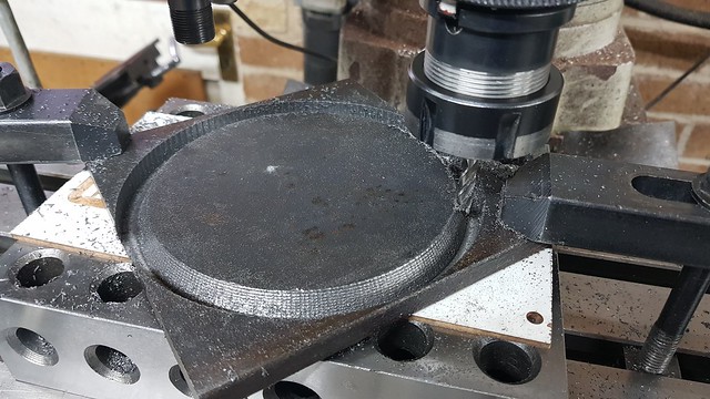 20201104_090358 20201104_090358 by Roger Froud, on Flickr The fittings are all the same, spot faced, a 1.2mm deep 'O' ring groove and tapped M8 x 0.75 (fine)  20201104_121939 20201104_121939 by Roger Froud, on Flickr The outside came off easily with a saw and then it was just a matter of taking a file to it to get it to fit. The rod is my standard Male threaded piece for M8 x 0.75 (fine) and that came in useful as a handle.  20201104_124447 20201104_124447 by Roger Froud, on Flickr A couple of magnetic bases held it all in place after a good wipe with Acetone. I wiped down the rods too.  20201104_140755 20201104_140755 by Roger Froud, on Flickr What was tacked in place, and adjusted with a mallet to get it all flat, and then the first root pass was done in stages. I could see that melting nicely right down in the bottom of the joint, so I know that's a solid start to the weld.  20201104_141402 20201104_141402 by Roger Froud, on Flickr So far, so good. That's three passes and at least two or three more to fill it right up. You can't do too much in one session because it gets too hot to handle. I've got a 'TIG finger' from Welding tips and tricks.com web store, but even with that it gets too hot to touch. Anyway, I'm pretty happy with it so far. It won't wind a beauty contest, but it won't fall off either! It's probably plenty strong enough even now, but I'll fully weld it since I can.  20201104_185347 20201104_185347 by Roger Froud, on Flickr |
|
|
|
Post by delaplume on Nov 4, 2020 21:29:47 GMT
Hi Roger, Looking at your excellent welding reminded me that it ought to be registered at a "Certain place in London"......... and from that memory came another which I hope you don't mind me posting on here ?? As you can see it's of an early GWR Castle class ( actually a re-built Star class No.4009 )..........The name and No. is of that "Certain place in London" that I referred to...  |
|


