|
|
Post by delaplume on Nov 21, 2020 19:45:24 GMT
Hi Roger, Just going back to the safety valve, should there be a locking ring? Anyone know if there are any regs about this. Paul Hi Paul, As this is a private test boiler designed, built and operated outside of the Public Domain, and of minimal size, I don't think any regs. apply apart from common sense and good engineering practice of course---- both of which Roger posses in abundance !! ... Naturally I stand to be corrected but hope that we as Engineering individuals still have some leeway of creative expression before the creeping tentacles of H.M. Inspectorate force us to become assimilated !! For guidance you could refer to the ME Boiler Test Code 2018, paras 11.8 -----11.9------11.10 but remember this is for boilers being operated within a Public envoiroment...... I imagine Roger will want a certain degree of adjustability to test injectors through varying pressure settings... |
|
|
|
Post by Roger on Nov 21, 2020 20:00:59 GMT
Hi Roger, Just going back to the safety valve, should there be a locking ring? Anyone know if there are any regs about this. Paul Hi Paul, As this is a private test boiler designed, built and operated outside of the Public Domain, and of minimal size, I don't think any regs. apply apart from common sense and good engineering practice of course---- both of which Roger posses in abundance !! ... Naturally I stand to be corrected but hope that we as Engineering individuals still have some leeway of creative expression before the creeping tentacles of H.M. Inspectorate force us to become assimilated !! For guidance you could refer to the ME Boiler Test Code 2018, paras 11.8 -----11.9------11.10 but remember this is for boilers being operated within a Public envoiroment...... I imagine Roger will want a certain degree of adjustability to test injectors through varying pressure settings... Hi Alan, Indeed I will want to test the injectors at different pressures, but I intend to set the safety valves slightly above the max working pressure of the locomotive ie at 100psi. The idea is to use the temperature control box to determine the pressure by temperature alone. I've got a thermistor probe that goes in the hole where the usual crude thermostat goes. This gives feedback to a Phase Angle Control circuit which compares that to the set temperature. How quickly and well this responds in practice is another thing, but in principle, I think this ought to work ok. So the Safety valves are supposed to be exactly that, just for safety in this application. |
|
|
|
Post by mugbuilder on Nov 21, 2020 23:56:34 GMT
G,Day Roger, Here in Australia the AMBSC code calls for all safety valves to have some sort of locking device. In practic though, only pop valves really need it as they are prone to have the adjustment unscrew when blowing off and we don't want the guts to blow out under pressure. Anyway as this boiler is for home use you should be able to do as you please and your boiler would need a stick of dynamite to burst it. Interesting to follow its progress.
Regards Barry.
|
|
|
|
Post by Roger on Nov 22, 2020 0:06:28 GMT
G,Day Roger, Here in Australia the AMBSC code calls for all safety valves to have some sort of locking device. In practic though, only pop valves really need it as they are prone to have the adjustment unscrew when blowing off and we don't want the guts to blow out under pressure. Anyway as this boiler is for home use you should be able to do as you please and your boiler would need a stick of dynamite to burst it. Interesting to follow its progress. Regards Barry. Hi Barry, Thanks for that, it's probably advisable to do that here too. I imagine the vibration might cause it to move as it blows off. As it happens the threads are a bit on the snug side, so it probably wouldn't happen on my examples. On the locomotive there are GWR type safety valves which have a bridge which is held with locknuts. So that would be compliant with your code. As you say, it's not going to be relevant for the test boiler. |
|
stevep
Elder Statesman

Posts: 1,070
|
Post by stevep on Nov 22, 2020 10:02:00 GMT
Very interesting question.
I think you're right Nobby - there is no requirement to have a locking ring or other form of ensuring the safety valve setting cannot move - but in my opinion there should be.
Having said that, I don't have any such device on the safety valves of my Rob Roy, and when raising steam, I let the pressure build until the valves lift, and check that the pressure gauge is at the red line. In the thirty-odd years I have been steaming it, I have never been disappointed! I think the pressure of the spring holds the adjuster in place.
|
|
JonL
Elder Statesman
WWSME (Wiltshire)
Posts: 2,906
|
Post by JonL on Nov 22, 2020 10:19:00 GMT
I didn't make my safeties as it was a bit too safety critical for my level of expertise but I've just recalled there are two miniscule Allen bolts on the top rim of the valves holding the adjustable portion in place.
|
|
|
|
Post by delaplume on Nov 22, 2020 13:25:42 GMT
Hello all, On a GWR Safety valve, whilst the locknuts indeed prevent the unit from coming loose, the more important items are the steel tubes that are slid over the retaining studs and make contact underneath the bridge piece........These prevent the spring from being over-compressed, a trick much favoured by loco crews in the past to get more power out of the engine.........After assembly in the Workshops the valve is tested on an Hydraulic rig and the tubes changed or adjusted ( Turned in the lathe ) until the required lifting pressure is obtained....... generally 225psi whilst the 4-6-0 Counties were 280psi and the 2-6-0 Moguls were at 200psi....... 
 |
|
|
|
Post by Roger on Nov 22, 2020 22:06:10 GMT
Hello all, On a GWR Safety valve, whilst the locknuts indeed prevent the unit from coming loose, the more important items are the steel tubes that are slid over the retaining studs and make contact underneath the bridge piece........These prevent the spring from being over-compressed, a trick much favoured by loco crews in the past to get more power out of the engine.........After assembly in the Workshops the valve is tested on an Hydraulic rig and the tubes changed or adjusted ( Turned in the lathe ) until the required lifting pressure is obtained....... generally 225psi whilst the 4-6-0 Counties were 280psi and the 2-6-0 Moguls were at 200psi.......
Hi Alan, That's exactly what I've done. It takes the guesswork out of stripping and reassembling it. |
|
|
|
Post by Roger on Nov 22, 2020 22:24:26 GMT
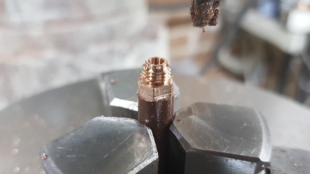
Continuing with the balanced clack test valve... This is the steam inlet fitting... 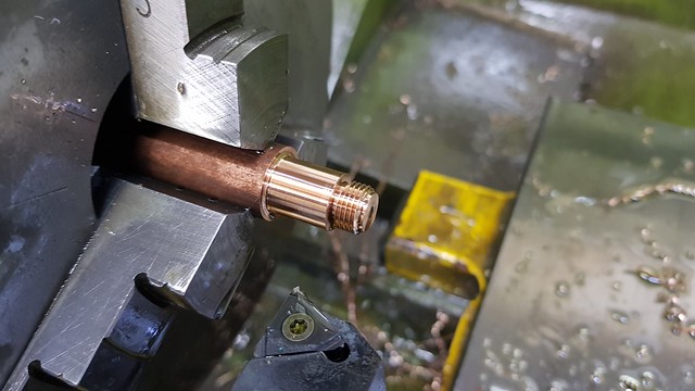 20201121_211846 20201121_211846 by Roger Froud, on Flickr ... and this is the 4mm piston rod.  20201121_211858 20201121_211858 by Roger Froud, on Flickr The steam inlet end again, with the M10 x 1 (fine) end firmly attached to the Steel holder...  20201122_111727 20201122_111727 by Roger Froud, on Flickr ... ready for screw cutting the M7 x 0.75 (fine) thread for the union nut.  20201122_115807 20201122_115807 by Roger Froud, on Flickr This is the water inlet end ready to be screw cut.  20201122_122940 20201122_122940 by Roger Froud, on Flickr I think this is out of sequence, it's the steam inlet end...  20201122_151918 20201122_151918 by Roger Froud, on Flickr ... while this is back to the M8 x 0.75 (fine) thread for the water nipple  20201122_154907 20201122_154907 by Roger Froud, on Flickr That's finally getting the hex added.  20201122_191737 20201122_191737 by Roger Froud, on Flickr For some reason I've failed to photograph the body being made, but it's pretty simple with the exception of the internal lobes which needed a very long 2mm cutter to get into the corners that deep. That took a couple of hours after roughing with a 4mm cutter. Still it's not a race, I don't care how long it takes while I'm making something else. Anyway, here's the said body with the outlet tube pressed into the register ready for Silver Soldering with Tippex stopping the big ring of Silver Solder from flowing down the sides, making a mess.  20201122_212127 20201122_212127 by Roger Froud, on Flickr  20201122_212538 20201122_212538 by Roger Froud, on Flickr Again, it's more Silver Solder than I need, but I wanted it to be rugged since it's going to have a hose pushed and pulled on the outlet tube. I aimed for a mere 5% nip on the piston O-ring because I want it to move freely. That feels about right, but I'll need to conduct a test to see how much pressure it takes to move it. I can always shave a tiny bit more off the ID if necessary. So the water inlet is 5mm pipe and the steam one is 4mm which is what the Injector will be using. Obviously the steam pipe could have been smaller, but I want it to be robust. I just need to find a 6mm Ceramic ball, crush that into the seat and then assemble it.  20201122_214553 20201122_214553 by Roger Froud, on Flickr |
|
|
|
Post by Roger on Nov 23, 2020 18:48:12 GMT
I've just slimmed down the Test Boiler Steam Valve now that I'm going to have to fit two of them onto a manifold. One is for the Injector steam, the other is for the Balanced Clack Valve. The design is basically the same, just shrunk down to use a M8 x 0.75 (fine) thread.  Small steam outlet valve Small steam outlet valve by Roger Froud, on Flickr The manifold is held on with a banjo bolt. I'm not sure whether I'll fit these at 90 degrees or something a little less.  Boiler assembly with manifold Boiler assembly with manifold by Roger Froud, on Flickr |
|
|
|
Post by Roger on Nov 24, 2020 21:33:42 GMT
The Carbide boring bars arrived from Banggood today, and they all have 4mm shanks. However, I don't have a holder for those, so it's time to make one. I had some 16mm square Steel in stock, so I chopped off a length and drilled a 4mm through it with a 4mm Aircraft Extension Drill which I happened to have.  20201124_125719 20201124_125719 by Roger Froud, on Flickr Then it was just a matter of facing it off and slitting it.  20201124_165041 20201124_165041 by Roger Froud, on Flickr Here's a wobbly video of that process. I'm using 10mm/min feedrate and a low RPM to keep the noise to a minimum. 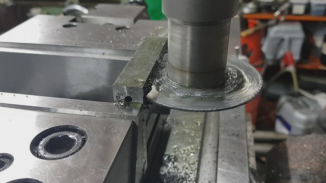 20201124_165058 20201124_165058 by Roger Froud, on Flickr A simple job, but pleasing nonetheless. 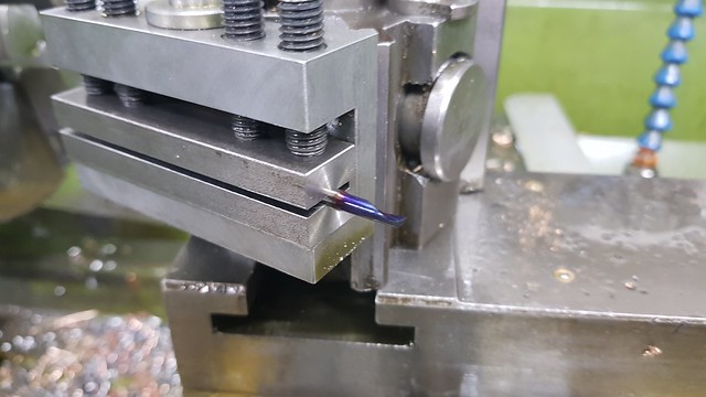 20201124_205039 20201124_205039 by Roger Froud, on Flickr I found a 35mm piece of Stainless Steel which already had a 10mm hole and a boss. I thought I'd make use of 3mm of that and the full diameter instead of the 30mm originally planned, so this is what I ended up with. Here I've programmed it to face off, rough and finish the tapped size to 7mm depth and create the O-ring pocket. That was embedded in that little program I showed to index it four times through 90 degrees. So I was able to let that do all four sides while I had my lunch.  20201124_151336 20201124_151336 by Roger Froud, on Flickr I then opened out three of them to 7.2mm and tapped them M10 x 1 (fine) The last one I just tapped as deeply as I could so it can be set up again and finished if I ever need another outlet. I've done three so I can put the Pressure Gauge on there too. Now the outlets come out horizontally, I may as well put it on the top. The front hole will get blanked off.  20201124_153149 20201124_153149 by Roger Froud, on Flickr That was then parted off and finished. The undercut on the inside was done on the first operation.  20201124_154159 20201124_154159 by Roger Froud, on Flickr This is the Banjo Bolt getting screw cut...  20201124_172534 20201124_172534 by Roger Froud, on Flickr ... the cross hole drilled...  20201124_173714 20201124_173714 by Roger Froud, on Flickr .. and the Hex added. 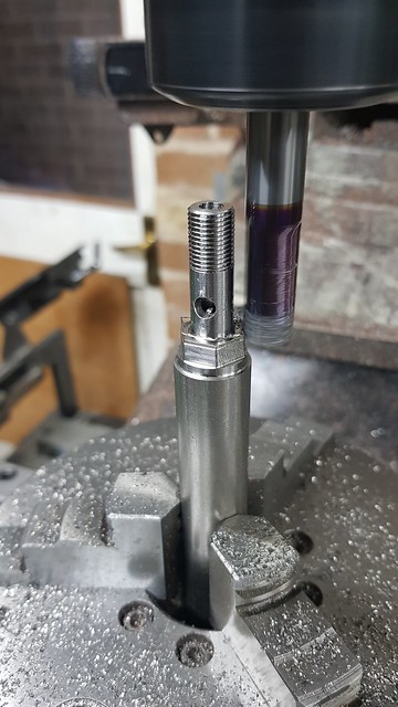 20201124_204229 20201124_204229 by Roger Froud, on Flickr The Copper washers were again made from Copper bar and annealed.  20201124_211043 20201124_211043 by Roger Froud, on Flickr Another step forward. I've got to wait for the Phosphor Bronze to arrive for the valve bodies, so I'll have get on with something else in the meantime.  20201124_211221 20201124_211221 by Roger Froud, on Flickr |
|
|
|
Post by 92220 on Nov 25, 2020 9:22:31 GMT
Hi Roger.
I have ordered some boring bars from Banggood too, after reading your post about them, earlier in the thread. I see the business end of yours is blue. Is it because the boring bars have brazed on tips or is it just discolouration due to grinding by the manufacturer?
Bob.
|
|
|
|
Post by Roger on Nov 25, 2020 11:38:27 GMT
Hi Roger. I have ordered some boring bars from Banggood too, after reading your post about them, earlier in the thread. I see the business end of yours is blue. Is it because the boring bars have brazed on tips or is it just discolouration due to grinding by the manufacturer? Bob. Hi Bob, I don't think it's either of those, I'm sure it's one of those coatings they apply to Carbide. The bars are definitely solid Carbide. |
|
|
|
Post by 92220 on Nov 25, 2020 15:01:21 GMT
Thanks Roger. Very confusing!! The colouring looks just like tempering on my screen!! When I get mine, I shall have to make some holders like yours.
Bob.
|
|
|
|
Post by Roger on Nov 25, 2020 22:52:14 GMT
|
|
|
|
Post by Roger on Nov 26, 2020 21:32:22 GMT
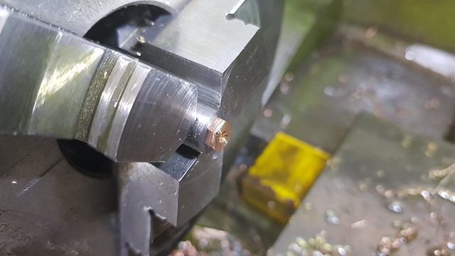
This is the shaft for one of the Test Boiler Steam Valves. I'm supporting the extended end with a centre because it's too slender to turn unsupported. It took a few cuts to adjust the tailstock so it was cutting parallel.  20201126_124038 20201126_124038 by Roger Froud, on Flickr The thread was screw cut M4 x 0.5 (fine) and tested in the gland.  20201126_130407 20201126_130407 by Roger Froud, on Flickr The end of the shaft has a 3mm long hex with 0.5mm radii so the handle can have the pocket machined with a 1mm cutter. A crude split holder was made to hold it.  20201126_191837 20201126_191837 by Roger Froud, on Flickr The end was then carefully trimmed.  20201126_211003 20201126_211003 by Roger Froud, on Flickr That's both of those done...  20201126_212202 20201126_212202 by Roger Froud, on Flickr ... and this is the first of the outlet unions.  20201126_205917 20201126_205917 by Roger Froud, on Flickr |
|
|
|
Post by Roger on Nov 27, 2020 17:27:05 GMT
This is the M7 x 0.75 (fine) outlet union for the second Steam Valve...  20201127_120059 20201127_120059 by Roger Froud, on Flickr .. here getting the hex added. M7 coarse is not really a preferred size, even though VW seem to make use of them. This is the 'fine' variety though which comes in very handy for those in between thread sizes.  20201127_111024 20201127_111024 by Roger Froud, on Flickr This is the body for one of the valves, with the new BangGood Carbide Boring Bars being put to good use. The fitting has three stepped diameters, the smallest being 6mm diameter. I drilled the centre to 3.2mm for the through hole and then used a 5.5mm Carbide end mill to plunge to the the full depth, all but 0.05mm. I often use a milling cutter to create that flat bottom of a hole, it saves a lot of time. Drilling is all very fine, but you have to stop well clear of the bottom and then work away at the tapered end that it leaves. Using an End Mill solves that problem and you can then quickly finish it with a boring bar and a single clean up cut on the bottom.  20201127_165737 20201127_165737 by Roger Froud, on Flickr I'm using an 8mm End Mill to create the Hex so that there's plenty of length and it's rigid.  20201127_162311 20201127_162311 by Roger Froud, on Flickr This is the first of the outlet unions waiting for the register to be turned. I'll finish the body first so that I can make this s press fit in the register on the body. I need to screw cut the thread on the body first though, so that I'll know where the outlet needs to be when it's done up tight.  20201127_170345 20201127_170345 by Roger Froud, on Flickr The Steam Valve body has an M8 x 0.75 (fine) thread and an 'O' ring groove.  20201127_212640 20201127_212640 by Roger Froud, on Flickr The last operation was to add the 30 degree chamfer on the back of the Hex  20201127_213201 20201127_213201 by Roger Froud, on Flickr So far so good. I just need to sort out the outlet hole positions and add those.  20201127_213522 20201127_213522 by Roger Froud, on Flickr |
|
stevep
Elder Statesman
Posts: 1,070
|
Post by stevep on Nov 27, 2020 18:35:56 GMT
SNIP I often use a milling cutter to create that flat bottom of a hole, it saves a lot of time. Drilling is all very fine, but you have to stop well clear of the bottom and then work away at the tapered end that it leaves. Using an End Mill solves that problem and you can then quickly finish it with a boring bad and a single clean up cut on the bottom. SNIP I have a number of D-bits that I have made over the years, which are perfect for making flat bottom holes. In fact, you can make the D-bit with a slight angled face, so the seat 'sits up' a bit from the bottom of the hole, which is great for ball seats. |
|
|
|
Post by simplyloco on Nov 27, 2020 19:30:20 GMT
SNIP I often use a milling cutter to create that flat bottom of a hole, it saves a lot of time. Drilling is all very fine, but you have to stop well clear of the bottom and then work away at the tapered end that it leaves. Using an End Mill solves that problem and you can then quickly finish it with a boring bad and a single clean up cut on the bottom. SNIP I have a number of D-bits that I have made over the years, which are perfect for making flat bottom holes. In fact, you can make the D-bit with a slight angled face, so the seat 'sits up' a bit from the bottom of the hole, which is great for ball seats. Agreed. I have lots, especially the ones for ME nuts! |
|
|
|
Post by Roger on Nov 28, 2020 21:22:41 GMT
I need to grind something for the Test Boiler, so it's time to quickly do the reamers for the Injectors so I can do that. I'm using the large fine wheel for this, trueing it for the first roughing and then again for the fine finishing touch.  20201128_171706 20201128_171706 by Roger Froud, on Flickr The 2mm HSS Drill Blank was clocked up to about 1 micron runout, and the angle set to 4.5 degrees for the first one.  20201128_194141 20201128_194141 by Roger Froud, on Flickr Here's a wobbly video of the rouging cut. 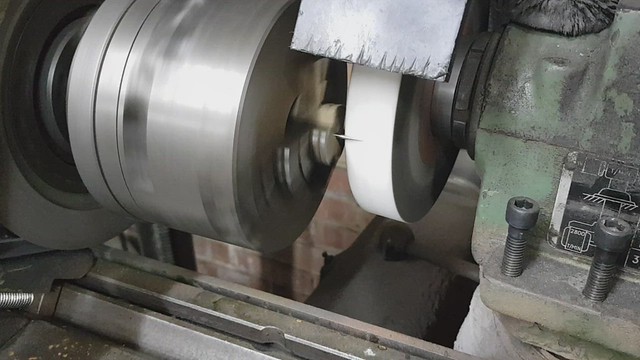 20201128_195349 20201128_195349 by Roger Froud, on Flickr This is the Delivery Cone Reamer which is 3.5 degrees half angle. 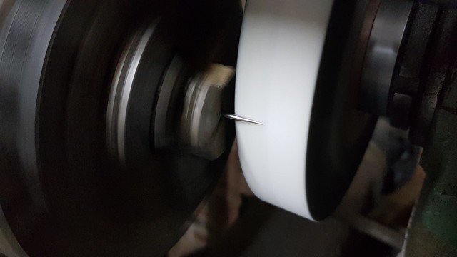 20201128_195338 20201128_195338 by Roger Froud, on Flickr I ground both ends for good measure. I just need to set the angle back to zero and grind them in half.  20201128_204712 20201128_204712 by Roger Froud, on Flickr |
|