|
|
Post by Roger on Jan 4, 2022 18:36:23 GMT
Having looked at a few lamp irons on Pannier tanks for my own engine I came to the conclusion that they were forged? Just a thought it would make them easy to make and very easy to be modified and weld into various positions. The panniers were of course made by many manufactures. That's certainly possible. I would imagine there would be telltale signs on some of them that would give away how they were made. I think you'd have to thin the tapered end before forging the rest of the shape, because I don't think there would be enough material to form the 'Stop' piece if you just forged it from a flat bar. It certainly makes sense to just make that top section and weld it to whatever mount you require. That allows for any height or orientation, many of which appear on 1501. |
|
|
|
Post by 92220 on Jan 4, 2022 19:15:15 GMT
I think Gary has hit the nail on the head...so to speak. Forging the lamp irons (brackets) does make sense. I hadn't thought of forging, but it would have been the easiest way to make those lamp brackets out of steel, and all the loco works had extensive forging facilities, and expertise. I know I called them 'iron#' in my previous post. I didn't mean they were made of iron, but they ARE 'lamp irons'. VERY confusing!!!
Bob.
Hi Roger.
Actually they could have forged them out of a single piece of flat. An alternative is that they could forge an extra piece on for the stop, while the steel is white hot, which effectively welds it in place. It would be easy to tidy the shape afterwards.
Bob.
|
|
|
|
Post by Roger on Jan 4, 2022 21:02:33 GMT
I think Gary has hit the nail on the head...so to speak. Forging the lamp irons (brackets) does make sense. I hadn't thought of forging, but it would have been the easiest way to make those lamp brackets out of steel, and all the loco works had extensive forging facilities, and expertise. I know I called them 'iron#' in my previous post. I didn't mean they were made of iron, but they ARE 'lamp irons'. VERY confusing!!! Bob. Hi Roger. Actually they could have forged them out of a single piece of flat. An alternative is that they could forge an extra piece on for the stop, while the steel is white hot, which effectively welds it in place. It would be easy to tidy the shape afterwards. Bob. Hi Bob, If they were forged from flat, I think it's more likely that they would upset the end where the 'Stop' is to get more metal at that end and then forge it between two dies so that it finished at the end with the 'Stop'. The rest of the Lamp Iron can then be flat bar, bent to any shape, and welded onto the bottom of it. |
|
|
|
Post by andyhigham on Jan 4, 2022 21:22:15 GMT
|
|
stevep
Elder Statesman

Posts: 1,070
|
Post by stevep on Jan 5, 2022 10:58:55 GMT
Gary,
Does that mean that the right-hand lamp iron in Roger's picture is actually a left-hand iron put on the wrong way round, as the 'nibs' that the lamp bracket should rest on are on different sides. So logically, it the lamps are put on so their brackets rest on the nib, one of them would be facing backwards!
|
|
|
|
Post by 92220 on Jan 5, 2022 12:19:06 GMT
Gary, Does that mean that the right-hand lamp iron in Roger's picture is actually a left-hand iron put on the wrong way round, as the 'nibs' that the lamp bracket should rest on are on different sides. So logically, it the lamps are put on so their brackets rest on the nib, one of them would be facing backwards! Hi. Just to make it clear, if you have a look at the photo of the front of the fullsize 1501, on Roger's thread, on the previous page to this one, you will see the 3 front lamp irons. The middle one and the left hand one (ON the loco), have the lamp support towards the right hand side of the loco, and the lamp iron on the right hand side of the loco, has the lamp support on the opposite side. Bob. |
|
Gary L
Elder Statesman
Posts: 1,208
|
Post by Gary L on Jan 5, 2022 18:28:48 GMT
Gary, Does that mean that the right-hand lamp iron in Roger's picture is actually a left-hand iron put on the wrong way round, as the 'nibs' that the lamp bracket should rest on are on different sides. So logically, it the lamps are put on so their brackets rest on the nib, one of them would be facing backwards! Hi. Just to make it clear, if you have a look at the photo of the front of the fullsize 1501, on Roger's thread, on the previous page to this one, you will see the 3 front lamp irons. The middle one and the left hand one (ON the loco), have the lamp support towards the right hand side of the loco, and the lamp iron on the right hand side of the loco, has the lamp support on the opposite side. Bob. Hi Steve and Bob Yep, it is clear, but only when you look for it...  The 'missing link' is that, unlike the other (i.e. lesser) Railway Companies, the GWR's lamps had a bracket on each side, rather than just one on the back. I imagine the enginemen were trained to always place them so the brackets rested on the 'nib', (though they would fit perfectly well the other way round). If they got it wrong, it would only displace the lamp by a 'lamp width and a bracket' i.e. not much. Because the bracket is 'sideways-on' to the lamp, this means that the brackets were not generally symmetrically positioned on any GWR loco or vehicle, so that the lamps themselves would be. (But less so on the 15xx, because there was mostly fresh air where the fastenings needed to be!) No doubt there was a very good reason for this (and I doubt if it was reduced wind resistance!). From Broad Gauge days onwards, the GWR seldom cared to follow anybody else's practices... WRT the 15xx, your sharp eyes have spotted a variation in the 'nib' position that I hadn't noticed when I made mine for Paddington, so I've almost certainly got it wrong  But the lamp irons at the front seem to have been an improvisation, which the erecting shop varied while the class was being built (and subsequently). So the message has to be (as ever) if you really care about these things, trust only a decent photo that is contemporary with the period you are building. You then run the risk of somebody thinking that your accurate copy looks so wrong that it can't possibly be right... Gary |
|
|
|
Post by Roger on Jan 5, 2022 21:34:56 GMT
I could have filed the tapered sides, but it's just as easy and more accurate to machine them. I used the High Speed Spindle, a 1.5mm PCB Burr and 0.2mm deep cuts which did them in no time.  20220104_210259 20220104_210259 by Timothy Froud, on Flickr Then it was just a matter of adding the rivet holes...  20220105_095107 20220105_095107 by Timothy Froud, on Flickr ... rounding the corners of the base and tidying it all up with a file. One more job ticked off. I've lightly countersunk the top of the rivet holes so I can flush rivet those them to the Cylinder Cladding.  20220105_212149 20220105_212149 by Timothy Froud, on Flickr |
|
don9f
Statesman
 Les Warnett 9F, Martin Evans “Jinty”, a part built “Austin 7” and now a part built Springbok B1.
Posts: 960 
|
Post by don9f on Jan 5, 2022 23:45:20 GMT
They look superb!
Don
|
|
dscott
Elder Statesman
Posts: 2,438
|
Post by dscott on Jan 6, 2022 0:04:30 GMT
The Very early Great Western Locos did in fact have square brackets for lamps, which would also superbly be made by CNC or Adam Cro in his growing collection. These are about 2 inches square by an inch deep IN FULL SIZE he adds. Perhaps they jolted out over rough track so had to have deeper pockets.
I know Churchward was once in trouble for spending twice as much per Locomotive than the other company's at the time. But on looking back they did cost less to run via maintenance and many are still running. Superb testament.
David and Lily.
|
|
dscott
Elder Statesman
Posts: 2,438
|
Post by dscott on Jan 6, 2022 0:08:33 GMT
OOPS What has Roger done to his vice jaw now?
Noticing many little holes perfectly spaced.
No it is a ploy to see if we are all paying attention!
David and Lily.
|
|
|
|
Post by Roger on Jan 6, 2022 7:07:24 GMT
OOPS What has Roger done to his vice jaw now? Noticing many little holes perfectly spaced. No it is a ploy to see if we are all paying attention! David and Lily. Hi David, Is you look back into early last year, you'll see that I 'modified' the jaw to include those hole marks way back then. Collateral damage is inevitable when you use things, I don't worry about it. I know it really upsets some people, but it's water off a Duck's back to me. |
|
|
|
Post by 92220 on Jan 6, 2022 8:41:06 GMT
OOPS What has Roger done to his vice jaw now? Noticing many little holes perfectly spaced. No it is a ploy to see if we are all paying attention! David and Lily. Hi David, Is you look back into early last year, you'll see that I 'modified' the jaw to include those hole marks way back then. Collateral damage is inevitable when you use things, I don't worry about it. I know it really upsets some people, but it's water off a Duck's back to me. And I thought those holes were to lighten the vice to make it easier to lift on and off the mill !! Also, Roger....superb little lamp brackets (irons). Whether cast or forged, they really look the part !! Bob. EDIT: Interestingly, the B.R. drawing for lamp irons on classes 4, 5 and 9f are welded construction, and show the welds. I wonder what the drawing for the other B.R. classes show? Why would they be any different? Also, the lamp holding blade is tapered, like 1501, but they don't indicate how the taper is formed....machined or forged. Bob |
|
|
|
Post by delaplume on Jan 7, 2022 4:09:54 GMT
Hi guys !!.......... could someone guide me back to the photos showing that vent on the cab roof.....I'll tel you why later on if all goes to plan .... David--- I'll phone you asap for an update on the home track.....Alan
|
|
|
|
Post by Roger on Jan 7, 2022 12:31:07 GMT
Hi guys !!.......... could someone guide me back to the photos showing that vent on the cab roof.....I'll tel you why later on if all goes to plan .... David--- I'll phone you asap for an update on the home track.....Alan Hi Alan, I've just emailed you a link to my photo archive folder with the roof details in it. |
|
|
|
Post by delaplume on Jan 7, 2022 19:42:11 GMT
Thanks Roger----reply on it's way
|
|
|
|
Post by Roger on Jan 9, 2022 23:06:57 GMT
The cylinder end covers are held on with small hex bolts on 1501, but those are just cosmetic on mine. The end covers are held on with larger screws on the ends. 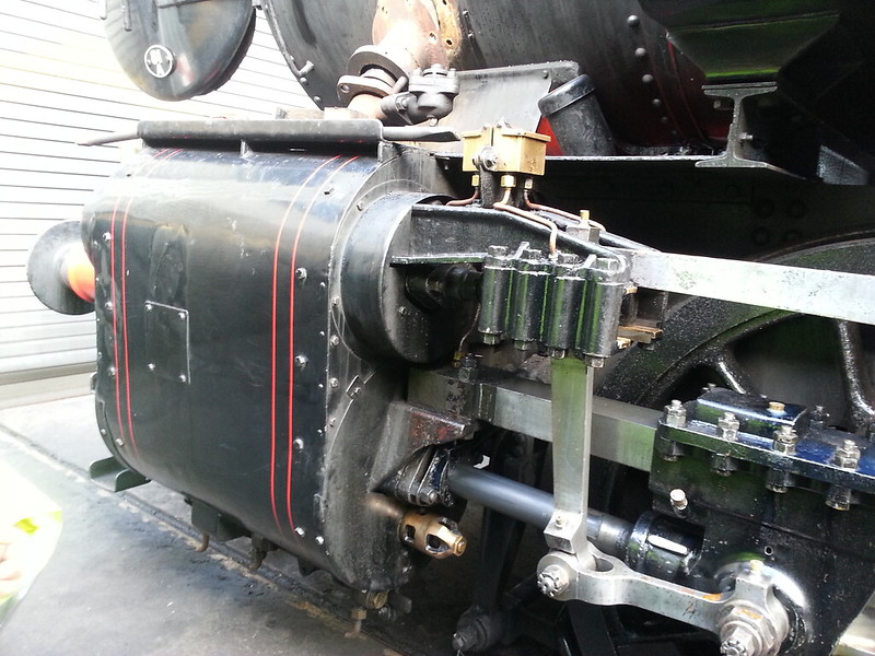 20140204_112524 20140204_112524 by Timothy Froud, on Flickr I hadn't drilled and tapped these holes, so I needed to do those now. Here's a piece of Nylon 66 that's been turned down to locate on the inside of the covers. It's getting an M6 tapped hole which lines up with the Pressure Relief Valve. I'm using an ER32 chuck to hold the drill because the chuck is too long to use when the 4th axis is this way up.  20220109_111227 20220109_111227 by Timothy Froud, on Flickr It's also too tall for the tap wrench sprung centre. I've used an ER32 collet to guide the tap and tightened the tap wrench on the smooth body. It's only tapping plastic, so that's plenty good enough. If it was for something else, I'd have ground a flat on the side of the tap for it to bite onto.  20220109_112028 20220109_112028 by Timothy Froud, on Flickr I made a small spacer washer to keep it central.  20220109_113117 20220109_113117 by Timothy Froud, on Flickr The holes are M1, so I've drilled them 0.85mm and tapped them so they can be fitted flush on the inside.  20220109_153804 20220109_153804 by Timothy Froud, on Flickr Finally, I added the flanged surround on the two front covers where the Relief Valves are. There aren't any on the rear ones on the full sized locomotive because the covers are split. I don't need to do that. I'd drilled the rivet holes for them on the rear ones, so those had to have rivets added and filed flush to get rid of them. Those came out well, I don't think you'll be able to see where they were once they're painted.  20220109_223925 20220109_223925 by Timothy Froud, on Flickr I've ordered a load of M1 bolts from Knupfer for all of these. I need to fit the four dummy bolts to the face of the front covers too. Those are held in place by a single bolt in the middle. In fact, the whole of the front cladding on the cylinders are held on by that too. Taking off the front cladding to get to the cylinder cover and bolts is done by unscrewing that single bolt. The back is a different matter of course, but hopefully that won't need taking off very often. It would probably be easiest to take off the whole cylinder assembly, cladding still attached. Although there's some fussy detail on the locomotive, it's pretty easy to get apart. Hopefully any future owner will take the trouble to look at the plans and not try to unscrew all the dummy bolts! The drawings and notes are going to take a lot of time to prepare. |
|
|
|
Post by chris vine on Jan 10, 2022 12:21:01 GMT
Hi Roger,
That is all great, as usual.
If you are not already, (more condensed than these thread entries), I think you should write up a set of simple notes for your successors. They will be useful if anyone ever wants to dismantle your masterpiece.
Simple things like which bolts/screws/nuts/pins need removing to take off part X.
Your fixings are so small that any misunderstandings will almost certainly result in broken parts which will be difficult to rectify!!!
Love it as always,
Happy New Year!
Chris.
|
|
|
|
Post by Roger on Jan 10, 2022 13:28:19 GMT
Hi Roger, That is all great, as usual. If you are not already, (more condensed than these thread entries), I think you should write up a set of simple notes for your successors. They will be useful if anyone ever wants to dismantle your masterpiece. Simple things like which bolts/screws/nuts/pins need removing to take off part X. Your fixings are so small that any misunderstandings will almost certainly result in broken parts which will be difficult to rectify!!! Love it as always, Happy New Year! Chris. Hi Chris, Thanks for that. I'm writing a set of assembly notes for the key parts, but I'll also make a complete set of annotated drawings so anyone can check what's a dummy and what isn't. |
|
|
|
Post by fubar123 on Jan 10, 2022 21:18:16 GMT
Enjoyed the first part of the articles on injectors in M.E. Roger. Well Done.
|
|


 But the lamp irons at the front seem to have been an improvisation, which the erecting shop varied while the class was being built (and subsequently). So the message has to be (as ever) if you really care about these things, trust only a decent photo that is contemporary with the period you are building.


