|
|
Post by 92220 on Jan 24, 2022 13:31:30 GMT
Hi Roger.
I'm sure Alan isn't in the driving seat any more, but I hope things get sorted. Your comments would seem to apply to other well known model engineering supply businesses, that were held in high regard, that have had a change of leadership in the past (some years ago now).
Bob.
|
|
|
|
Post by delaplume on Jan 24, 2022 15:55:30 GMT
Hi Roger dear friend, pal, chum etc.. and glad to see you are still maintaining that much-applauded "Independent Roger"approach......Now please don't shoot me, and I realise that skill and quality should not be rushed but it seems that for some the buffer stocks at Paddington are drawing ever closer and with it the knock on the front door from a Mr. G. Reaper Esq....So,when do you think the loco might be ready enough to put a fire in it and give it a test run ??..........( ducks down behind parapet )..... just asking, not trying to pressurise etc..OK ??
|
|
|
|
Post by Roger on Jan 24, 2022 16:44:57 GMT
Hi Roger dear friend, pal, chum etc.. and glad to see you are still maintaining that much-applauded "Independent Roger"approach......Now please don't shoot me, and I realise that skill and quality should not be rushed but it seems that for some the buffer stocks at Paddington are drawing ever closer and with it the knock on the front door from a Mr. G. Reaper Esq....So,when do you think the loco might be ready enough to put a fire in it and give it a test run ??..........( ducks down behind parapet )..... just asking, not trying to pressurise etc..OK ?? Hi Alan, A good question, deserving a sensible answer. This year is going to see the chassis completely finished. The aim is to get the Boiler fitted and the final details of the Pannier Tanks done, painted and erected. I also hope to have the bottom of the Cab and Bunker finished and painted. I hope to complete the top of the Cab and Bunker, assemble the Backhead components and finish some of the detail valves and Steam Whistle valves. I still have the pressure gauges to make, so that will be another side project. This time next year I'm hoping to be ready to put a fire in it. In truth, I could quickly put things together, and run it this year, but that's pointless when there's still so much to finish and fun to be had making more bits and pieces. There's no rush, it will be done soon enough. |
|
Gary L
Elder Statesman

Posts: 1,208
|
Post by Gary L on Jan 24, 2022 18:29:49 GMT
Ingenious as ever Roger, well done! I went for working model snifters on Paddington (before Adam produced his!) but even on 1:8 scale I couldn’t get the passage area I wanted, so I made them just a little overscale. I don’t think it will offend anybody, but they are a distinctive aspect of GWR locos and I like to hear the little “clop-hiss” that shows they are working. Gary PS. They don’t have to be on any particular side of the superheater, I have had them on the output side of the s/h on Bridget and they work just fine. It is the cylinders they are there to protect. IMHO the talk about cooling the s/h elements is a myth, they can’t possibly pass enough air to have any useful effect. But each to his own… I don't think the coolling of the superheaters is critical, but there's no harm in doing that. Personally, I think the effect will be significant since the temperature differential between atmospheric air and the Superheaters exposed in the firebox is huge. The volume will be similar to what Steam was being consumed prior to closing the regulator. If the locomotive has been pulling hard, and the regulator is shut, there's nothing to take away the heat any more, and the temperature on the exposed ends could soar without anything to cool them. Hi Roger Indeed there is no harm in doing that, they just need to be somewhere in the steam supply between the regulator and the steam chest. But for the removal of doubt, they do need to exist, somewhere. The drawings for Paddington show two options; one (sheet 17) is for a single snifter, connected to the regulator housing and the opening to atmosphere concealed within the smokebox saddle, which corresponds to your arrangement (and indeed LBSC's). The alternative (sheet 13) is for a replica of full size, with two snifters, one on each steam pipe. The former is probably more manageable in the smaller scales, but I chose the latter because 1.5" scale allows them to be bigger than 'watchmaking' size. I chose the latter, because it matches the technology of the prototype and "because I can". Either location is valid, but I don't think the 'superheater cooling' argument holds much water if you don't mind me saying so. I say this for two reasons, (1) theory and (2) experience. The 'theory' argument (not really) derives from full size. If there was a benefit from cooling the superheaters, Swindon would have done it (admittedly some other companies did, but not consistently). In reality Swindon termed them "steam chest air valves' (not superheater air valves) and by and large, superheated or not, if they were not mounted on the steam pipe, they were mounted directly on the steam chest, often emerging through the running plate. But the 'experience' argument clinches it for me. In full size, locos could run for long periods 'drifting' downhill with the snifters open. On miniature railways this hardly ever happens, because gradients are not long enough for the train weight to 'take charge' for any noticeable time. The only time I can be sure the snifters are open on Bridget is for the last few seconds of a run, when the train is coasting into the station. Hardly long enough to cool the superheaters at all, and with the regulator closed, the fire soon dies down anyway. A minor additional advantage of the 'exterior' location of the snifter is a reduction in clutter inside the smokebox. Experience with Bridget (a slide valve loco) is instructive in another way. I was once told that slide valve locos do not need snifters, and that may be the reason why Ken Swan did not include them in his design. But that is quite wrong, and misunderstands the purpose of the snifter. The snifter is not a pressure-release valve. When drifting, the slide valves do not lift; the pumping action of the cylinders with steam shut off sucks the valve more firmly onto its seat. To equalise the pressure difference, if there is no snifter, smokebox gases are sucked backwards down the blast-pipe, complete with a liberal spattering of grit and char. My Bridget had no snifters at first, and I could not understand why the cylinder draincocks were regularly getting blocked with grit. Then a 'light-bulb moment' told me what was missing. I fitted a single snifter to the superheater (only because it was the most convenient place). The transformation was remarkable. Without the snifter, when the regulator was closed, it was like putting the brakes on. With the snifter, the train coasts slowly to a halt in a very prototypical way. And no more trouble from blocked draincocks! To sum up, I have no quarrel with your snifter arrangement at all, but I think your reason for preferring the superheater location is liable to be misleading for newcomers. In truth, either location is as good as the other; the important thing is to make sure you have one (or more) fitted! Gary |
|
|
|
Post by Roger on Jan 24, 2022 18:40:34 GMT
I don't think the coolling of the superheaters is critical, but there's no harm in doing that. Personally, I think the effect will be significant since the temperature differential between atmospheric air and the Superheaters exposed in the firebox is huge. The volume will be similar to what Steam was being consumed prior to closing the regulator. If the locomotive has been pulling hard, and the regulator is shut, there's nothing to take away the heat any more, and the temperature on the exposed ends could soar without anything to cool them. Hi Roger Indeed there is no harm in doing that, they just need to be somewhere in the steam supply between the regulator and the steam chest. But for the removal of doubt, they do need to exist, somewhere. The drawings for Paddington show two options; one (sheet 17) is for a single snifter, connected to the regulator housing and the opening to atmosphere concealed within the smokebox saddle, which corresponds to your arrangement (and indeed LBSC's). The alternative (sheet 13) is for a replica of full size, with two snifters, one on each steam pipe. The former is probably more manageable in the smaller scales, but I chose the latter because 1.5" scale allows them to be bigger than 'watchmaking' size. I chose the latter, because it matches the technology of the prototype and "because I can". Either location is valid, but I don't think the 'superheater cooling' argument holds much water if you don't mind me saying so. I say this for two reasons, (1) theory and (2) experience. The 'theory' argument (not really) derives from full size. If there was a benefit from cooling the superheaters, Swindon would have done it (admittedly some other companies did, but not consistently). In reality Swindon termed them "steam chest air valves' (not superheater air valves) and by and large, superheated or not, if they were not mounted on the steam pipe, they were mounted directly on the steam chest, often emerging through the running plate. But the 'experience' argument clinches it for me. In full size, locos could run for long periods 'drifting' downhill with the snifters open. On miniature railways this hardly ever happens, because gradients are not long enough for the train weight to 'take charge' for any noticeable time. The only time I can be sure the snifters are open on Bridget is for the last few seconds of a run, when the train is coasting into the station. Hardly long enough to cool the superheaters at all, and with the regulator closed, the fire soon dies down anyway. A minor additional advantage of the 'exterior' location of the snifter is a reduction in clutter inside the smokebox. Experience with Bridget (a slide valve loco) is instructive in another way. I was once told that slide valve locos do not need snifters, and that may be the reason why Ken Swan did not include them in his design. But that is quite wrong, and misunderstands the purpose of the snifter. The snifter is not a pressure-release valve. When drifting, the slide valves do not lift; the pumping action of the cylinders with steam shut off sucks the valve more firmly onto its seat. To equalise the pressure difference, if there is no snifter, smokebox gases are sucked backwards down the blast-pipe, complete with a liberal spattering of grit and char. My Bridget had no snifters at first, and I could not understand why the cylinder draincocks were regularly getting blocked with grit. Then a 'light-bulb moment' told me what was missing. I fitted a single snifter to the superheater (only because it was the most convenient place). The transformation was remarkable. Without the snifter, when the regulator was closed, it was like putting the brakes on. With the snifter, the train coasts slowly to a halt in a very prototypical way. And no more trouble from blocked draincocks! To sum up, I have no quarrel with your snifter arrangement at all, but I think your reason for preferring the superheater location is liable to be misleading for newcomers. In truth, either location is as good as the other; the important thing is to make sure you have one (or more) fitted! Gary Hi Gary, I absolutely agree that they are needed for the reasons you mention. It's debatable whether the Superheater cooling is that beneficial, but I think you're mistaken in thinking it won't cool them much. Next time you Silver Solder a Copper pipe fitting on the end of a long length of tube, give it a quick blow through with the air line, and you'll see the temperature plummet to the point where you can handle it immediately. There's quite a lot of air being sucked through, as you know from your need to make them over scale. As for coasting, on one of our Fetes, there's a 150 yard downhill run from the station, and it's all done under gravity and takes a minute or more. Personally, I think the moment the regulator is closed, the air going through the Superheaters will have a very significant effect on their temperature. That may or may not be important, but I'm pretty sure it happens. I think we're probably going to have to agree to disagree on that point. |
|
mbrown
Elder Statesman
Posts: 1,719
|
Post by mbrown on Jan 24, 2022 19:00:35 GMT
To add a bit from experience - none of our locos on the Talyllyn have snifting valves. Nos. 1, 2 and 3 all have slide valves on vertical port faces. These definitely do drop away when steam is off - indeed, when you put steam back on again there is a definite blow of steam up the chimney and a "click" as the valves meet the port face again.
Nos. 4 and 6 have slide valves on port faces on top of the cylinder block. When coasting - which we do for virtually the whole of the 7 mile down journey - they roll extremely freely. Drivers are taught to coast in full gear. There is no evidence, either in the way they roll or in terms of muck in the cylinders, of pumping or of smokebox char being "inhaled".
No.7 has piston valves and Barclay's gave her rather inadequate flat by-pass valves which don't seat well and may even have been fixed closed as they rattled themselves until they leaked. She rolls like the proverbial brick - we run downhill with a breath of steam on and the lever in the next notch to middle. The difference from the slide valve locos is massive. All the slide valve locos roll very freely with the regulator shut provided they are in full gear.
Malcolm
|
|
|
|
Post by Roger on Jan 24, 2022 20:08:54 GMT
To add a bit from experience - none of our locos on the Talyllyn have snifting valves. Nos. 1, 2 and 3 all have slide valves on vertical port faces. These definitely do drop away when steam is off - indeed, when you put steam back on again there is a definite blow of steam up the chimney and a "click" as the valves meet the port face again. Nos. 4 and 6 have slide valves on port faces on top of the cylinder block. When coasting - which we do for virtually the whole of the 7 mile down journey - they roll extremely freely. Drivers are taught to coast in full gear. There is no evidence, either in the way they roll or in terms of muck in the cylinders, of pumping or of smokebox char being "inhaled". No.7 has piston valves and Barclay's gave her rather inadequate flat by-pass valves which don't seat well and may even have been fixed closed as they rattled themselves until they leaked. She rolls like the proverbial brick - we run downhill with a breath of steam on and the lever in the next notch to middle. The difference from the slide valve locos is massive. All the slide valve locos roll very freely with the regulator shut provided they are in full gear. Malcolm So the slide valve allows air to cycle back and forth through the Steam Chest, and there's no tendency to draw air in from the Blast Pipe because there's a fixed volume being moved. |
|
Gary L
Elder Statesman
Posts: 1,208
|
Post by Gary L on Jan 24, 2022 20:29:02 GMT
To add a bit from experience - none of our locos on the Talyllyn have snifting valves. Nos. 1, 2 and 3 all have slide valves on vertical port faces. These definitely do drop away when steam is off - indeed, when you put steam back on again there is a definite blow of steam up the chimney and a "click" as the valves meet the port face again. Nos. 4 and 6 have slide valves on port faces on top of the cylinder block. When coasting - which we do for virtually the whole of the 7 mile down journey - they roll extremely freely. Drivers are taught to coast in full gear. There is no evidence, either in the way they roll or in terms of muck in the cylinders, of pumping or of smokebox char being "inhaled". No.7 has piston valves and Barclay's gave her rather inadequate flat by-pass valves which don't seat well and may even have been fixed closed as they rattled themselves until they leaked. She rolls like the proverbial brick - we run downhill with a breath of steam on and the lever in the next notch to middle. The difference from the slide valve locos is massive. All the slide valve locos roll very freely with the regulator shut provided they are in full gear. Malcolm I admit that my observation wouldn't be true for vertical or underhung slide valves- I was thinking about the common arrangement with valves on top of the cylinders as in Bridget. I couldn't comment about pumping (or lack of it), but it definitely happened on Bridget. A matter of valve timing perhaps? Gary |
|
|
|
Post by keith1500 on Jan 24, 2022 21:09:35 GMT
I don’t see how air can be drawn down the blast pipe when coasting unless the driver has stuffed the reverser opposite to the direction in which the loco is running.
The sniffing valve just prevents a vacuum being created on the supply side.
|
|
|
|
Post by delaplume on Jan 24, 2022 21:16:26 GMT
E.J. Nutty describes them as "Snifting or Steam Chest Air Valves" and being fitted to}--"Piston valve engines and engines with Balanced Slide valves".... ..... amongst other things he says}--- "they prevented pressure building up in the steam chests if the regulator ( or the lubricator combining valve ) was leaking when shut by dropping open under their own weight.....This prevented the loco moving if the cylinder drain cocks were shut"....
He goes on to say}--- "They also prevented as far as possible the formation of a vacuum in the steam chests by the pumping action of the Pistons when the engine was drifting"......( but crucially doesn't say which pistons he's referring to.....can't be the Piston valves as they are of the Snap type and would be in the Relaxed position when drifting....)...
He goes on to say}--- "When an engine was drifting with the lever in full gear there was a continual tendency for a vacuum to be formed in the steam chests ( my words}--ie between the valve heads for an inside admission piston valved loco )..The cold air which was drawn in through the snifting valves to the steam chests cooled the cylinders and was exhausted through the blast pipe"....
An interesting note at the end says}---"Locomotives of the following classes were built with balanced slide valves, but later fitted with outside admission semi-plug piston valves :- Duke, Bulldog, Badminton, Atbara, Flower, and Aberdare"....
PS--- just me being pedantic maybe but valves are "Set" not timed....that's for ICE, CIE etc...
Also..... for those not aware who Mr. E.J. Nutty was please do a "Google" search---it'll be worth your efforts ...
|
|
|
|
Post by delaplume on Jan 24, 2022 21:27:05 GMT
I seem to remember that GWR reversers had a "drifting notch or rivet head" marked at something like 15% ???
|
|
|
|
Post by keith1500 on Jan 24, 2022 21:30:21 GMT
Interesting. Perhaps the issue is the vacuum is pulling the slide valve on to its face which without steam might be starved of lubricant and thereby damaged?
Hence the drifting notch.
|
|
|
|
Post by delaplume on Jan 24, 2022 21:35:26 GMT
I don’t see how air can be drawn down the blast pipe when coasting unless the driver has stuffed the reverser opposite to the direction in which the loco is running. The sniffing valve just prevents a vacuum being created on the supply side. But in "reverse" can be useful----This was an old trick used in the MPD if you needed to get some sort of pressure in the boiler if lighting-up hadn't gone to plan---but in this case the loco was "Dead" and being shunted back and forth by an 08 with the reverser in the opposite direction and the regulator opened and shut appropriately... Trust me on this one Gentlemen-- it works and Raveningham Hall was eventually put into Sunday morning traffic--albeit a few hours behind timetable !!....... My thanks to the late John Hurley for this lifesaver !!.. |
|
|
|
Post by Roger on Jan 24, 2022 21:57:58 GMT
To add a bit from experience - none of our locos on the Talyllyn have snifting valves. Nos. 1, 2 and 3 all have slide valves on vertical port faces. These definitely do drop away when steam is off - indeed, when you put steam back on again there is a definite blow of steam up the chimney and a "click" as the valves meet the port face again. Nos. 4 and 6 have slide valves on port faces on top of the cylinder block. When coasting - which we do for virtually the whole of the 7 mile down journey - they roll extremely freely. Drivers are taught to coast in full gear. There is no evidence, either in the way they roll or in terms of muck in the cylinders, of pumping or of smokebox char being "inhaled". No.7 has piston valves and Barclay's gave her rather inadequate flat by-pass valves which don't seat well and may even have been fixed closed as they rattled themselves until they leaked. She rolls like the proverbial brick - we run downhill with a breath of steam on and the lever in the next notch to middle. The difference from the slide valve locos is massive. All the slide valve locos roll very freely with the regulator shut provided they are in full gear. Malcolm I admit that my observation wouldn't be true for vertical or underhung slide valves- I was thinking about the common arrangement with valves on top of the cylinders as in Bridget. I couldn't comment about pumping (or lack of it), but it definitely happened on Bridget. A matter of valve timing perhaps? Gary I can certainly see how a slide valve on top would need a Snifting valve. As the piston moves each way, one side is trying to lift the valve while the other is trying to suck it down. |
|
|
|
Post by Roger on Jan 24, 2022 22:03:10 GMT
I don’t see how air can be drawn down the blast pipe when coasting unless the driver has stuffed the reverser opposite to the direction in which the loco is running. The sniffing valve just prevents a vacuum being created on the supply side. When coasting, the inlet is open to the Steam chest so it will draw a partial vacuum in there as the piston moves. Then the valve closes at the point where Steam cutoff happens. The piston is still moving though, so the pressure in the Cylinder drops even further. Eventually the exhaust valve opens, and the vacuum is exposed to the Blast pipe. |
|
|
|
Post by keith1500 on Jan 24, 2022 22:17:17 GMT
Good explanation.
Hence the practice on the Talyllyn of coasting in full gear would minimise the vacuum drawn.
|
|
|
|
Post by Roger on Jan 24, 2022 22:23:51 GMT
This is the top half of the Cosmetic Steam Tube Cover. The OD has been turned with the dummy sleeve being kept sharp using the HSS tool and a parting tool on the back. The through hole has been drilled and reamed 10mm in case I need a precision reference from the inside. The end clearance pocket was added too. 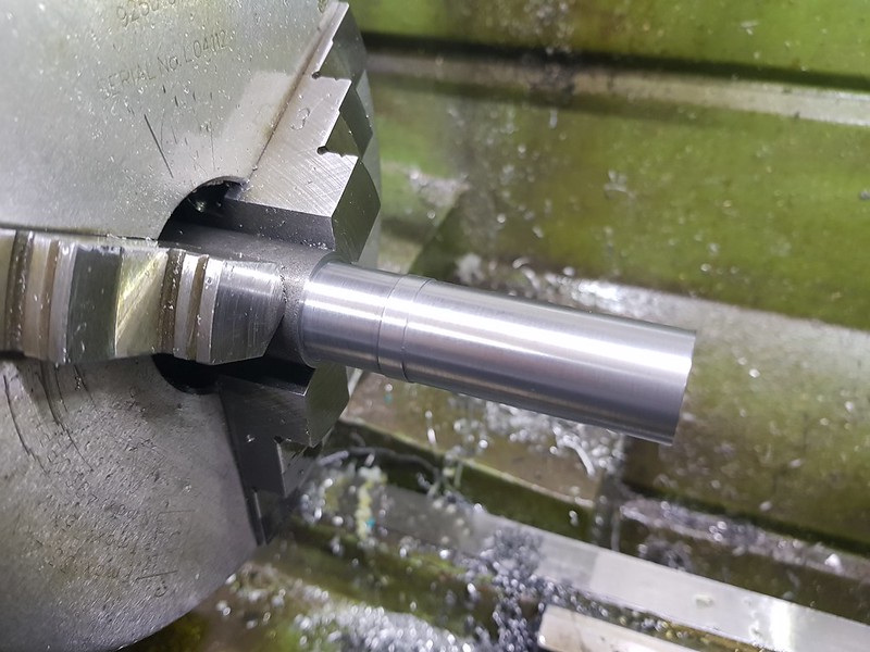 20220124_110428 20220124_110428 by Timothy Froud, on Flickr Here's a quick sanity check, slowly stepping and checking it's not going to do something unexpected. 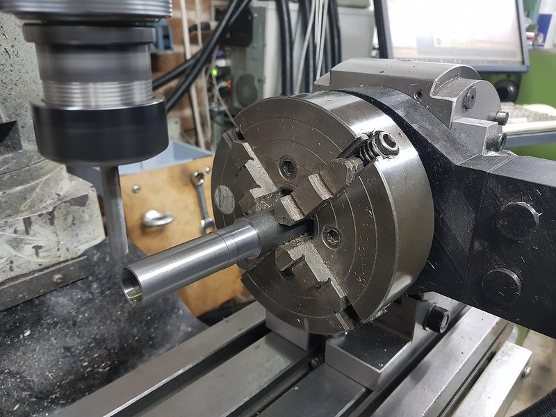 20220124_120236 20220124_120236 by Timothy Froud, on Flickr I hadn't left enough clear of the chuck, as you can see here where I've moved it further out and clocked it all in again. I clock the trueness near the chuck and then check further out, using a mallet to true it up. The next sanity check revealed that it was going to take a huge cut on the corner, so I just cut that off with a saw. 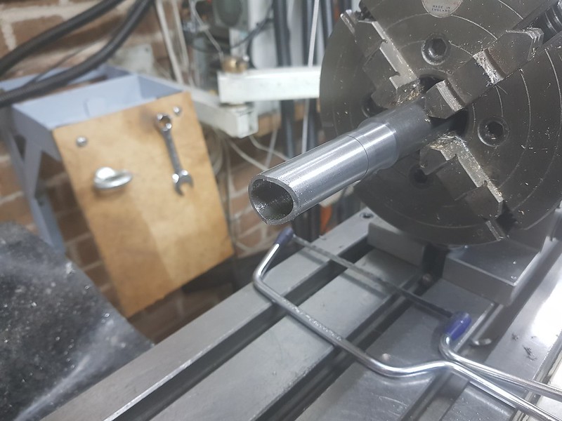 20220124_122705 20220124_122705 by Timothy Froud, on Flickr That now cleared, and the tool holder also missed the chuck at the other end.  20220124_122910 20220124_122910 by Timothy Froud, on Flickr I'm machining at the full depth, but only 0.1mm deep cuts at 150mm/min. The whole thing took an hour to finish. I could have sawn some away, but why bother. 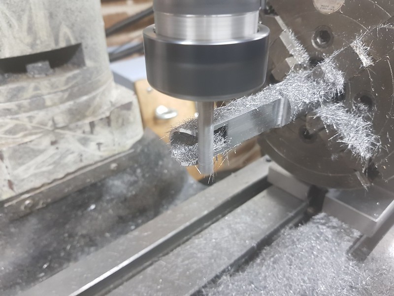 20220124_133115 20220124_133115 by Timothy Froud, on Flickr The Snifting Valve flange sits in a 3mm deep pocket and will be Silver Soldered in place. I may well tack it with the TIG welder to make sure it stays put while I do that. 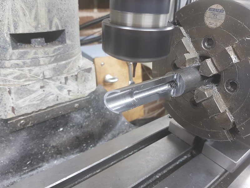 20220124_162908 20220124_162908 by Timothy Froud, on Flickr It's deliberately made as a pocket so that the flange has a location to sit on to aid assembly.  20220124_170228 20220124_170228 by Timothy Froud, on Flickr There are four dummy M1 hex bolts on the side and two 0.8mm Rivets at the RH side. The M1 ones were drilled 0.9mm to make them easy to tap. These are on both sides, so the 4th axis was turned 180 degrees and a Y-mirrored drilling program was used for the other side.  20220124_174237 20220124_174237 by Timothy Froud, on Flickr Then the 2.6mm deep pockets were machined for the Smarium Cobalt Magnets that hold this all together. I've chosen this type because it has a Curie point in excess of 310C That guarantees they're not going to lose their magnetism when it all gets hot and fall off! 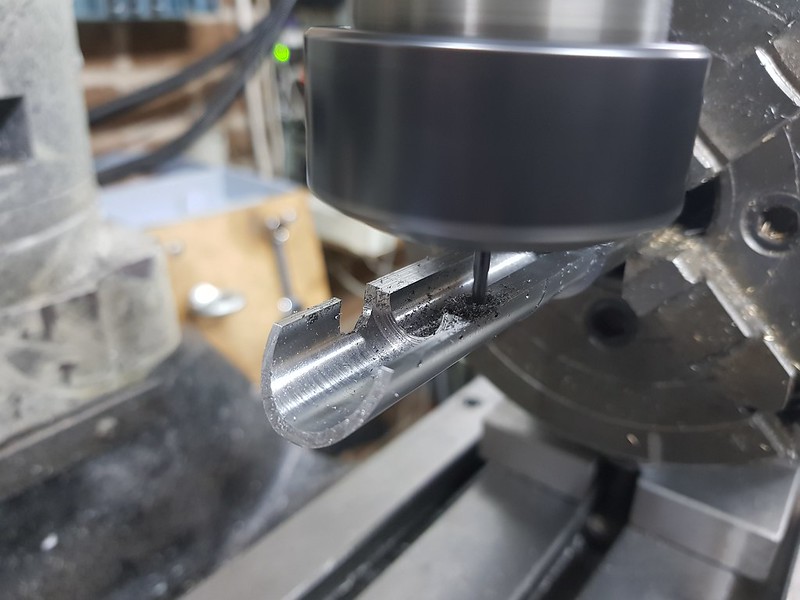 20220124_182631 20220124_182631 by Timothy Froud, on Flickr The magnets are 4mm diameter and 5mm long, so I've made the pockets 2.6mm deep. I may bond one side in, but it probably won't be necessary  20220124_212659 20220124_212659 by Timothy Froud, on Flickr Then it was just a matter of parting it off... 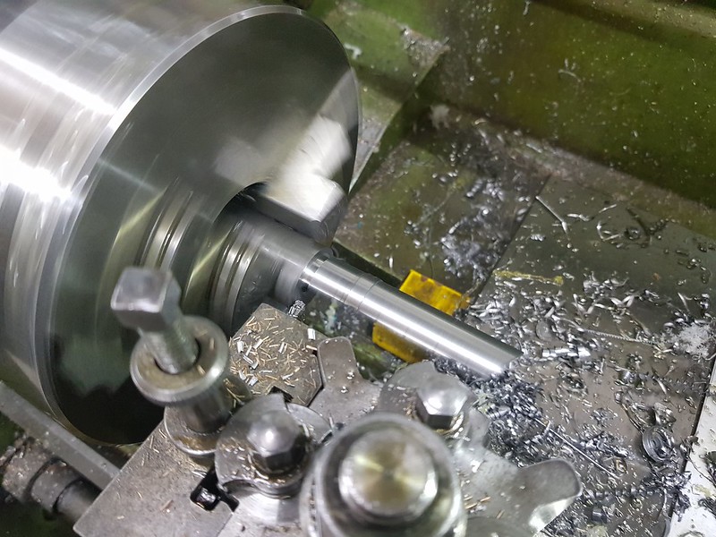 20220124_213300 20220124_213300 by Timothy Froud, on Flickr ... and tidying up the sharp edges with Diamond needle files.  20220124_214333 20220124_214333 by Timothy Froud, on Flickr So far so good. This is the easy bit. I'll probably make the mirrored one of these before I move on to the bottom pieces. |
|
|
|
Post by Roger on Jan 25, 2022 20:46:56 GMT
Here's the second, mirrored one of the top pieces. I just made it the same way as the last one, but turned the A-axis through 180 degrees and mirrored the cutout for the Snifting Valve Flange. 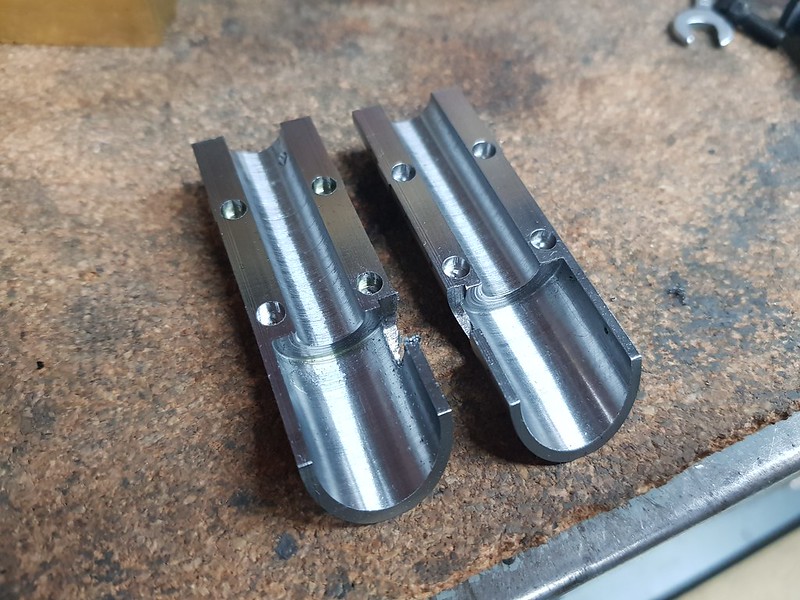 20220125_203727 20220125_203727 by Timothy Froud, on Flickr This is much the same as the top half, but it's going to be mostly machined away to leave just one quarter. The diameter of the band is the same, but the rest is slightly smaller than the top to give the illusion that the top sheet overlaps the bottom half.  20220125_110559 20220125_110559 by Timothy Froud, on Flickr So I need four of these to make the four bottom quarters. Yes, I know it's wasteful of material, but Steel is very cheap and it's an easy way to make them. I could have offset a smaller diameter piece in the 4-jaw to turn the OD and set it up on a mandrel in the 4th Axis. That's a lot of faffing about when I can just hold it all on the centre line of the bar and reference all of the operations from that.  20220125_203646 20220125_203646 by Timothy Froud, on Flickr |
|
|
|
Post by Roger on Jan 26, 2022 21:35:19 GMT
Here's a video showing the second of the two top halves being cut from the round. I'm only using a 0.1mm deep cut, so 150mm/min is fine.  20220125_212147 20220125_212147 by Timothy Froud, on Flickr This is the first of the bottom quarters after the initial cutting in half.  20220126_081704 20220126_081704 by Timothy Froud, on Flickr 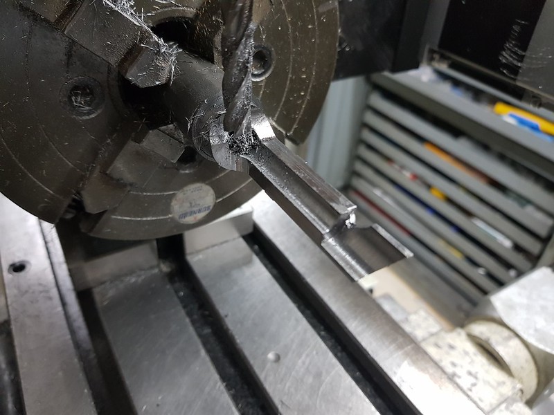 20220126_093542 20220126_093542 by Timothy Froud, on Flickr The magnet holes have a 0.1mm clearance to allow for easy fitting and a bit of a protective coating.  20220126_113448 20220126_113448 by Timothy Froud, on Flickr The other side uses the same spacing and offsets, so I can use a mirrored program for those. 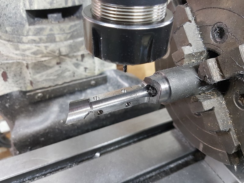 20220126_123441 20220126_123441 by Timothy Froud, on Flickr This is the third of the four bottom quarters, so I ought to finish this stage tomorrow. 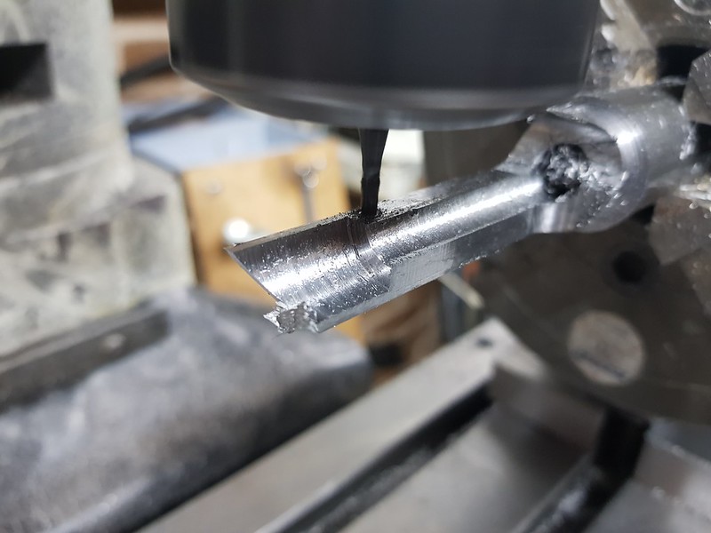 20220126_212051 20220126_212051 by Timothy Froud, on Flickr They're coming along nicely. The magnets provide just the right amount of grip without making it difficult to remove. The top half is removed first, then the bottom halves are separated.  20220126_212144 20220126_212144 by Timothy Froud, on Flickr The tricky bit is making the flange details and attaching them. |
|
dscott
Elder Statesman
Posts: 2,438
|
Post by dscott on Jan 27, 2022 1:54:04 GMT
Superb Roger a carefully thought out way of doing things.
A long list of your hints and tips growing by the day.
Just think of the curved steam pipe covers for the Locomotive at the front of the train done the same way.
Just imagine being at Paddington for this.
CNC solves just so many problems.
David and Lily.
|
|


