|
|
Post by Roger on Jan 23, 2023 15:54:08 GMT
This is the Jockey Valve for the Hydrostatic Lubricator...  20180110_111731 20180110_111731 by Timothy Froud, on Flickr ... which is operated by the link that tracks the movement of the Regulator pin. It's a dummy on my build,but it's pretty prominent, and I've got the rest of the linkage for it too. 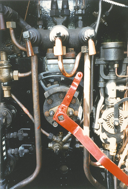 Backhead12 Backhead12 by Timothy Froud, on Flickr This is pretty small, so I've decided to make it from PB102 so it will take some shallow threads without them getting stripped. Here I've machined the top with the 3mm radius mill and now we're about to start on the other side. The cutter is just about long enough to reach the middle which is Zero for the CAM output. The Z-axis is told not to go lower than that during this operation.  PXL_20230119_102014932 PXL_20230119_102014932 by Timothy Froud, on Flickr  PXL_20230119_210134949 PXL_20230119_210134949 by Timothy Froud, on Flickr This one of the sides...  PXL_20230120_084453148 PXL_20230120_084453148 by Timothy Froud, on Flickr ... and finally the last side. You can see that I've extended the 3D model so that the rectangular fixing boss on the back it 5mm longer. Then I've put a containment region around that to stop it cutting the whole thing off!  PXL_20230120_084515390 PXL_20230120_084515390 by Timothy Froud, on Flickr 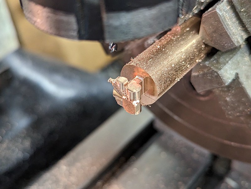 PXL_20230120_135307271 PXL_20230120_135307271 by Timothy Froud, on Flickr Then it was on to the 1mm Ball nosed cutter which is too short to reach to the middle. Each of the cutter depths for the four orientations had to be adjusted so that the length of the flutes wasn't exceeded. Here I'm setting the Z-axis to the chuck radius which I know accurately, touching the cutter down to set the Zero position to the axis of rotation for the 4th axis.  PXL_20230120_140343544 PXL_20230120_140343544 by Timothy Froud, on Flickr Then the slow process of Horizontal and Parallel Finishing had to be done on all 4 sides to get the bulk of the detail in place. The key to this is to use the centre of the part for the Zero, then just spin the axes through 90 degrees each time. Because the axis goes through the centre of the part, each set of machining operations line up. Click on the picture to see the video.  PXL_20230120_143123497.TS PXL_20230120_143123497.TS by Timothy Froud, on Flickr  PXL_20230120_181352189 PXL_20230120_181352189 by Timothy Froud, on Flickr  PXL_20230120_192307499 PXL_20230120_192307499 by Timothy Froud, on Flickr  PXL_20230121_130019772 PXL_20230121_130019772 by Timothy Froud, on Flickr Then each hole had to be set up for drilling and tapping. You have to be really careful to get the right angles and offsets for each hole.  PXL_20230121_195011318 PXL_20230121_195011318 by Timothy Froud, on Flickr It was then turned up on end and clocked up again to the middle of the bar...  PXL_20230121_205157910 PXL_20230121_205157910 by Timothy Froud, on Flickr ... and the end finished.  PXL_20230121_205209975 PXL_20230121_205209975 by Timothy Froud, on Flickr You can finally get on with some more reasonable feedrates once the roughing is complete. Click on the picture to see the video.  PXL_20230123_111403400.TS PXL_20230123_111403400.TS by Timothy Froud, on Flickr 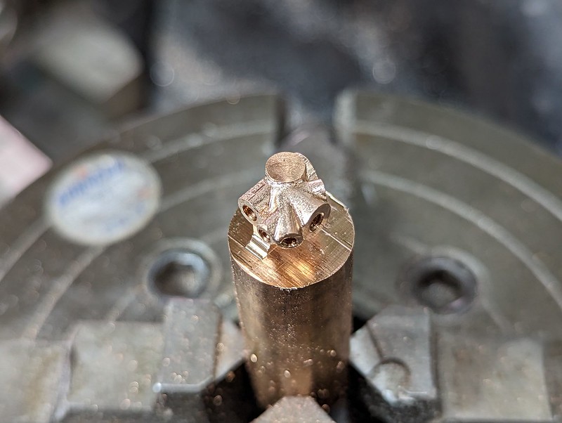 PXL_20230123_121638889 PXL_20230123_121638889 by Timothy Froud, on Flickr  PXL_20230123_123031949 PXL_20230123_123031949 by Timothy Froud, on Flickr It was then parted off and set in the machine vice for cleaning up the end... 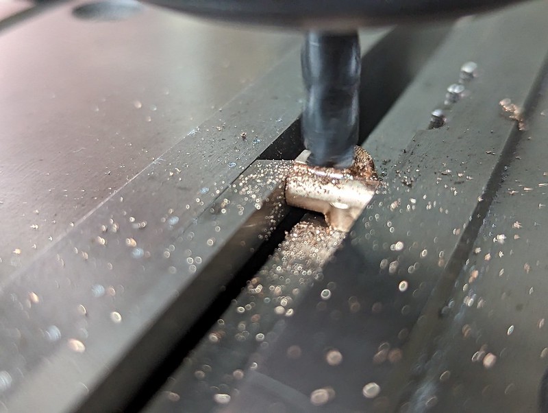 PXL_20230123_131455624 PXL_20230123_131455624 by Timothy Froud, on Flickr ... and adding the M1.4 fixing holes. I have no idea how this is fixed on the real thing, but you can't see it anyway so it doesn't matter.  PXL_20230123_132259105 PXL_20230123_132259105 by Timothy Froud, on Flickr And this is what it looks like in the end. Not a lot to show for three days of solid machining.  PXL_20230123_132914991 PXL_20230123_132914991 by Timothy Froud, on Flickr |
|
|
|
Post by Roger on Jan 23, 2023 22:40:27 GMT
More progress on the Smokebox today, with all of the key elements in place. I've ordered a 14mm Crow's Foot spanner to make removing the Steam pipes form the Superheater easier. I 3D printed a Hexagonal spacer that stays in the 10mm Hex driver that I'll keep with the tool kit. That enables the Blower Banjo to be fitted without the hex disappearing inside the driver, allowing the Copper washer to fall off. I can't stand things being fiddly to assemble when they don't need to be. 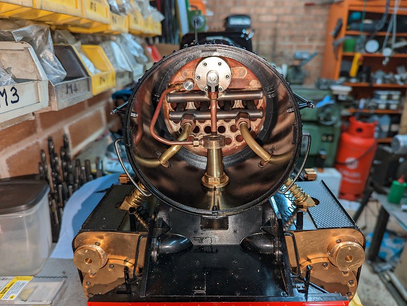 PXL_20230123_204428602 PXL_20230123_204428602 by Timothy Froud, on Flickr The Snifting valve is in the Banjo that's on the face of the Regulator flange. It all went together very easily, there's not much in the Smokebox and it's all easily accessible.  PXL_20230123_204359610 PXL_20230123_204359610 by Timothy Froud, on Flickr I've just ordered some White Enamel to paint the numbers on the Header and Shed plates, and then those can go on. It looks pretty bare without those.  PXL_20230123_213840559 PXL_20230123_213840559 by Timothy Froud, on Flickr The Cosmetic Steam covers were a bit tight, I'll have to take a look and see what's stopping them from going on easily. If you recall, those are just held on by Stainless Steel location pins and two Sumarium Cobalt magnets. 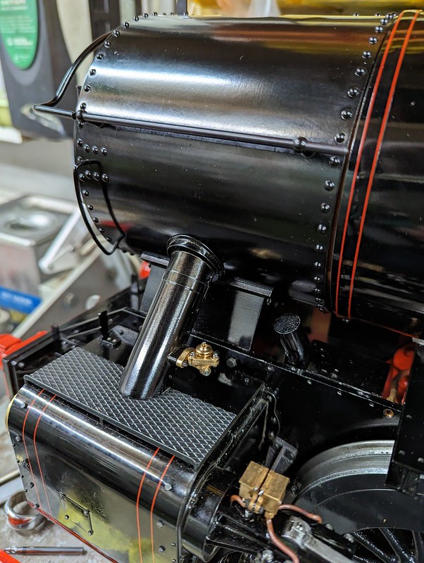 PXL_20230123_214621570 PXL_20230123_214621570 by Timothy Froud, on Flickr I finally got round to Blacking the Petticoat Pipe, so that's on too. This goes on without having to remove the blast pipe which is handy.  PXL_20230123_220849063 PXL_20230123_220849063 by Timothy Froud, on Flickr It's held on by two M4 Stainless Cap Heads so it's easy to remove. The taper of the Petticoat pipe continues inside the Chimney, all the way to the top.  PXL_20230123_220910276 PXL_20230123_220910276 by Timothy Froud, on Flickr The Chimney slides over that, there being two pockets to clear the Cap Heads. I need to 3D Print a painting support for the Chimney, then that can be painted. I'll probably do that as part of the next batch of painting.  PXL_20230123_220955281 PXL_20230123_220955281 by Timothy Froud, on Flickr |
|
mbrown
Elder Statesman

Posts: 1,717
|
Post by mbrown on Jan 23, 2023 22:52:18 GMT
Well done for painting the handrails black as per prototype! The temptation to leave them bright can be very strong, but you stayed firm! I shall have to do the same on 99 3462 - and overcome the urge to have chrome boiler bands as it does now in preservation but never did before!
Your loco is really looking good.
Malcolm
|
|
|
|
Post by Roger on Jan 23, 2023 23:10:48 GMT
Well done for painting the handrails black as per prototype! The temptation to leave them bright can be very strong, but you stayed firm! I shall have to do the same on 99 3462 - and overcome the urge to have chrome boiler bands as it does now in preservation but never did before! Your loco is really looking good. Malcolm Thanks Malcolm. I'm modelling it on what it looks like now, so it was an easy choice. The front curved handrail is painted, but the side rails are Blacked. |
|
JonL
Elder Statesman
WWSME (Wiltshire)
Posts: 2,906
|
Post by JonL on Jan 25, 2023 20:27:44 GMT
I'm genuinely excited to see this coming together.
|
|
|
|
Post by Roger on Jan 25, 2023 21:28:58 GMT
Thanks Jon, I'm really enjoying finally putting all those little bits and pieces together. They've been sitting in boxes for too long. This is the 3D printed mount for the Chimney so I can hold it on the painting rotisserie. I've added a little flexibility to the OD so it's not a struggle to get on and off. These things only take a couple of minutes to design because I've already got a model for the basic thread. All I have to do is copy that model and add a few simple details to make each mount. It took about ten minute max to design and get this onto the printer, then two hours to print. 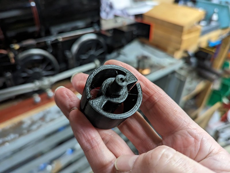 PXL_20230125_212042863 PXL_20230125_212042863 by Timothy Froud, on Flickr Being able to turn things when you're painting them is a game changer. You can get to every position you need without performing acrobatics with the gun. Gravity is always changing direction when you turn things horizontally, so you don't get any runs, unlike if you use a turn table.  PXL_20230125_212101402 PXL_20230125_212101402 by Timothy Froud, on Flickr |
|
|
|
Post by Roger on Jan 27, 2023 21:22:26 GMT
This is the Dummy Lubricator...  Hydrostatic lubricator assembly Hydrostatic lubricator assembly by Timothy Froud, on Flickr ... which ought to end up like this hopefully.  20180110_110352 20180110_110352 by Timothy Froud, on Flickr I bought a piece of 32mm SAE660 Leaded Bronze from Macc Models for this. I had some Brass, but can look too Yellow and spoil the appearance. It's hanging out a long way because it won't go through the 4th axis mandrel. The cuts are only light, so it won't matter. A few words on the issues with machining like this might be in order. Firstly, the stock isn't conveniently situated in the centre of the 3D model, so I drew a circle around the cross section to find out where the part fits with a little room all round. That turned out to be 3.64mm up from the centre. The machining origin was moved to Z3.64 too, so that I could clock the stock exactly on the centre of rotation. This is really useful, because you can then use the Edge Finder front and back near the end of the bar and halve it to set the centre in the Y axis. The end of the bar is made to X-0.2mm to make sure the end is cleaned up. The end of the bar is X0 in the 3D CAM output. Setting it up this way means you can go into the CAM module and index the reference around the X axis, 90 degrees at a time, and the part is still in the correct orientation without changing any offsets. Mecsoft CAM isn't smart enough to do the same with the Stock definition. That has to be set up for each orientation which is a pain. Once the Horizontal Roughing has been done, the stock isn't used any more, so that's a blessing. This is a 4mm cutter being used to remove the bulk of the material.  PXL_20230125_213001487 PXL_20230125_213001487 by Timothy Froud, on Flickr It's tempting to use a bigger cutter and deeper cuts, but the problem with that strategy is that you leave big steps for a smaller cutter to remove. Obviously you can use multiply cutters and gradually go down the sizes to do it as quickly as possible. However, that requires more programs and more tool changes and I'm not in a big hurry. I'm trading simplicity for less time on the job myself. I don't care how long it takes to machine as long as it can do it quietly without me having to be there.  PXL_20230126_080603867 PXL_20230126_080603867 by Timothy Froud, on Flickr There's no point in trying to reach deeply from each side. As long as you can remove the bulk of the material after machining from each side, that's all you need.  PXL_20230126_144907201 PXL_20230126_144907201 by Timothy Froud, on Flickr Mecsoft CAM doesn't allow you to define Round stock only Rectangular, so it does waste a fair bit of time machining fresh air. 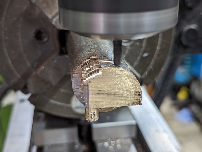 PXL_20230126_150121659 PXL_20230126_150121659 by Timothy Froud, on Flickr  PXL_20230126_153911496 PXL_20230126_153911496 by Timothy Froud, on Flickr  PXL_20230126_184819268 PXL_20230126_184819268 by Timothy Froud, on Flickr Once roughed out, I used a short 1.5mm Carbide End Mill to remove the rest of the roughed material. The flute length is pretty short, so I couldn't go as deep as the roughed cut.  PXL_20230127_092025086 PXL_20230127_092025086 by Timothy Froud, on Flickr  PXL_20230127_150207560 PXL_20230127_150207560 by Timothy Froud, on Flickr 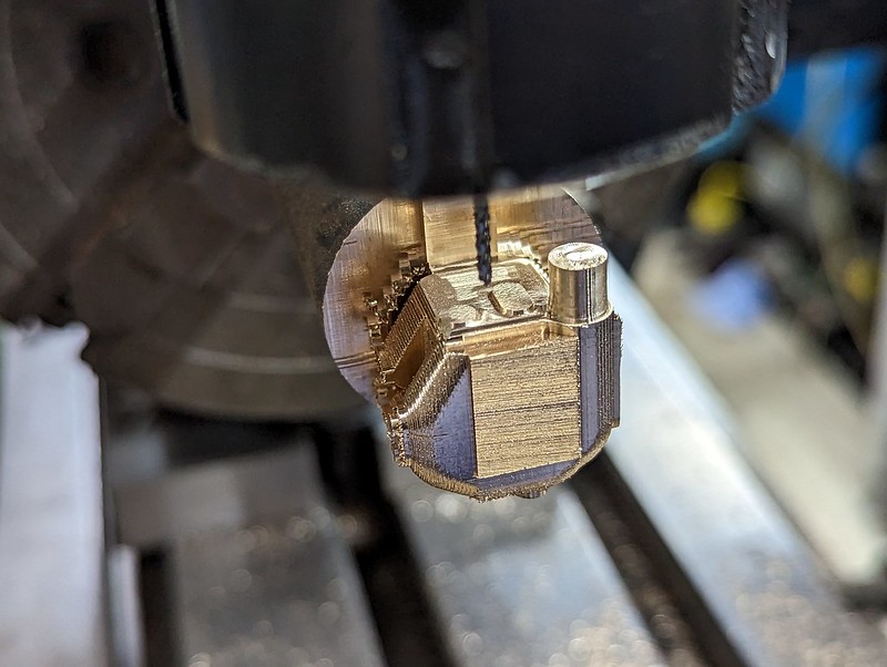 PXL_20230127_151241692 PXL_20230127_151241692 by Timothy Froud, on Flickr I then switched to a 10mm long 1.5mm PCB burr which was used to Parallel Finish the profiles on each face.  PXL_20230127_152650046 PXL_20230127_152650046 by Timothy Froud, on Flickr I'm using a 0.02mm step over so that it produces an acceptable finish. The cutter is really long and fragile, so I just take it really slowly and let it get on with it. This is the progress after two days of gentle machining. I'm not always around to start it off again in another operation, so quite a lot of time is wasted.  PXL_20230127_204918877 PXL_20230127_204918877 by Timothy Froud, on Flickr Obviously you'd make this a casting or machine it at a rapid rate on a 5-axis machine, getting into all the nooks and crannies with stout cutters that taper down to a ball end to finish it. It's not feasible to do it that way with the equipment I have. In the end, all I care about is that it's possible. If it takes a week to machine, so be it. As long as it's not annoying the neighbours, all is well. As it stands, I can run this all night and you'd never know it was working from outside in the street. This still might go pear shaped, it's very easy to crash the tool or load the wrong program for the orientation you're using. I single step every new program the first few blocks at very slow feeds to make sure it looks plausible before running continuously. It's also very easy to miss something catastrophic in the tool path. On one path it decided to plunge into a hole, even though the hole was suppressed in the model, explicitly to avoid that. It's not the first bug that's almost caused a crash. In the end, you're the one responsible to checking that it looks right. If you don't understand something about the way it looks, don't run it until you do! |
|
jma1009
Elder Statesman
Posts: 5,900
|
Post by jma1009 on Jan 28, 2023 22:57:21 GMT
Very nice to see the chimney again and all that it connects with! The late Bob Youlden would be very proud of your work.
Cheers,
Julian
|
|
|
|
Post by mugbuilder on Jan 28, 2023 23:55:09 GMT
A stunning job Roger. This engine will be too good to use and will deserve to be placed in a glass case and be on permanent exhibition in a museum somewhere. I suspect however that this will not be the case and will be put to work on a club track. I hope that when this momentous day comes that you will provide us mere mortals with some great photos and details of its performance.
Regards, Barry
|
|
|
|
Post by Roger on Jan 29, 2023 6:04:41 GMT
Very nice to see the chimney again and all that it connects with! The late Bob Youlden would be very proud of your work. Cheers, Julian Thanks Julian, the reason the Chimney, Petticoat Pipe and all the internals of the Smokebox are so accessible and easily disassembled is because I took on board your comments about how difficult and restricted these can be to work on. I also appreciate the time you took to work out the ideal draughting dimensions. Bob and his Wife were very welcoming when we went over to pick up a copy of the GA and see his workshop. it's a real shame he's not still with us. |
|
|
|
Post by Roger on Jan 29, 2023 6:08:31 GMT
A stunning job Roger. This engine will be too good to use and will deserve to be placed in a glass case and be on permanent exhibition in a museum somewhere. I suspect however that this will not be the case and will be put to work on a club track. I hope that when this momentous day comes that you will provide us mere mortals with some great photos and details of its performance. Regards, Barry That's very kind of you Barry, but I've seen the work you've posted and it's superb. You're absolutely right about this being intended as a workhorse locomotive. There are some fiddly bits on the outside, but under that facade, there's a simple and robust set of parts that should withstand a hard life. I fully expect some issues when it finally gets steamed. There are a few things that are experimental, so it would be surprising if it went smoothly. Rest assured I'll show what happens. |
|
|
|
Post by terrier060 on Jan 29, 2023 20:06:30 GMT
Breathless as always Roger at such lovely CNC work and all your other inovative work on what will be a Speedy unlike any other. So glad you have got the chimney and bonnet looking right. So many fail to do this. I always tell my friends to look at your work and the work of others on this special internet site.
Ed
|
|
|
|
Post by Roger on Jan 29, 2023 21:35:44 GMT
A bit more progress on the dummy Hydrostatic Lubricator body. The final operation on the side finished overnight. It didn't quite clean up everything, but I can dress that with a file when it's complete.The problem lies with the amount of slack there is in the Mill Knee. I'm going to have to do something about that before too long.  PXL_20230129_085240738 PXL_20230129_085240738 by Timothy Froud, on Flickr While setting up in the vertical position, I managed to hit the Emergency Stop button after I'd jogged the 4th axis round. That meant I'd lost the orientation because there's no homing on the 4th axis. Here I've clamped a small piece of HSS tooling to the longest flat face I can access so that it could be clocked back to the right angle.  PXL_20230129_090701562 PXL_20230129_090701562 by Timothy Froud, on Flickr This is far from an ideal setup, it's all too tall given the accuracy issues with the knee.  PXL_20230129_091030401 PXL_20230129_091030401 by Timothy Froud, on Flickr However, repeatability matters more than absolute accuracy for this job, so it's not a huge problem. It does mean I can't tap the holes on the end though. 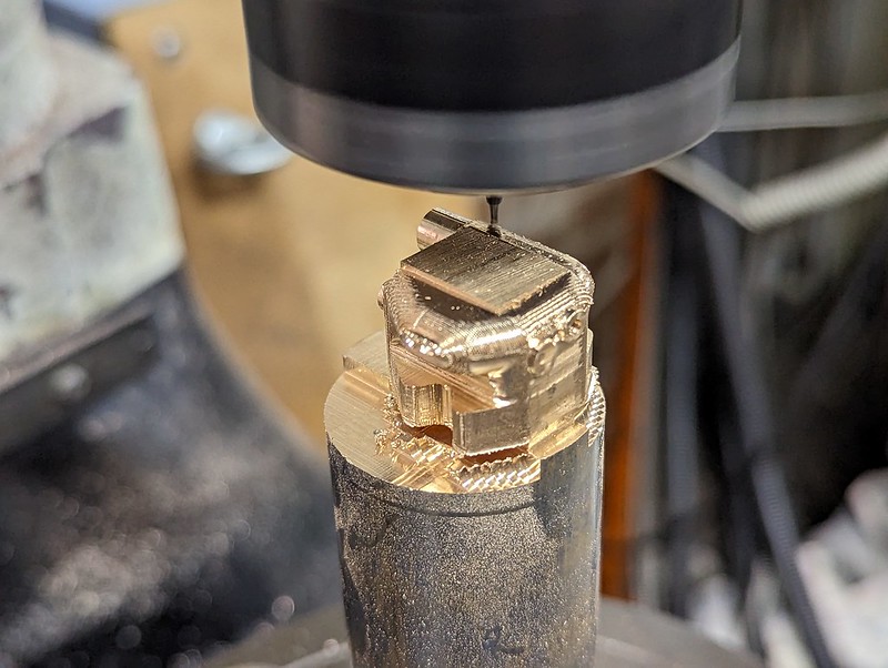 PXL_20230129_092845536 PXL_20230129_092845536 by Timothy Froud, on Flickr This is Parallel Finishing with a 20 micron step over (just under a thou).  PXL_20230129_110456832 PXL_20230129_110456832 by Timothy Froud, on Flickr Click to see the video.  PXL_20230129_110459254.TS PXL_20230129_110459254.TS by Timothy Froud, on Flickr Not I know it's not scrap, it's back on its side to add all of the location holes for the fittings. These ones are tapped M1.4 because they secure the top casting that holds the sight glasses.  PXL_20230129_151843286 PXL_20230129_151843286 by Timothy Froud, on Flickr The top location needed tidying up to get it really flat.  PXL_20230129_173842800 PXL_20230129_173842800 by Timothy Froud, on Flickr The fittings won't use threads, they will just be Loctited into the location holes.  PXL_20230129_174948963 PXL_20230129_174948963 by Timothy Froud, on Flickr Then it was just a matter of parting it off gently with a 3mm wide HSS blade which resists deflecting from side to side. Once the pip was removed and the surface flattened on the Surface Table with a bit of fine emery, it could be mounted in the Vice. Obviously this is a really tricky things to hold, so I 3D printed some Soft Jaws to get a good grip on the sides below the flange. I pulled out the flange features and made a 3D model of that with the centre in both axes being the reference. The Soft Jaws hold it in the centre, so I could use the Centre Finder on the inside of the Vice Jaws in the X axis and the top and bottom of the flange in the Y. I lightly spotted the drill holes first and had a quick sanity check on their positions before proceeding further. Here's the back being relieved to reveal the feet. I'm using 0.1mm deep cuts to keep the loads to a minimum.  PXL_20230129_211153474.TS PXL_20230129_211153474.TS by Timothy Froud, on Flickr |
|
|
|
Post by Roger on Jan 30, 2023 11:11:01 GMT
The rear machining finished without incident, even though it wasn't held that tightly.  PXL_20230130_104332168 PXL_20230130_104332168 by Timothy Froud, on Flickr This is how the 3D printed soft jaws fitted...  PXL_20230130_104355286 PXL_20230130_104355286 by Timothy Froud, on Flickr 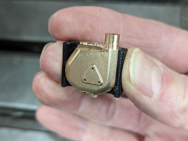 PXL_20230130_104417512 PXL_20230130_104417512 by Timothy Froud, on Flickr ... and how they look off the part. I used a Boolean subtraction option to just remove the part from a solid piece created as a block ad a 3d model.  PXL_20230130_104505044 PXL_20230130_104505044 by Timothy Froud, on Flickr There's a fair bit of work still to do with needle files to blend everything in and remove the burrs, especially where the tall round part meets the base. Machining it from five orientations is bound to result in small errors, regardless of how carefully you set it up. It's come out surprisingly well, considering. Hopefully the flange holes will line up with the studs on the Backhead.  PXL_20230130_104531886 PXL_20230130_104531886 by Timothy Froud, on Flickr |
|
|
|
Post by 92220 on Jan 30, 2023 17:23:43 GMT
Lovely job Roger...absolutely superb, as always!!
Bob.
|
|
|
|
Post by Roger on Jan 30, 2023 22:13:13 GMT
I'm trying to paint the raised Header and Shed plate numbers and letters white, so I thought I'd make a curved pad to try that with. 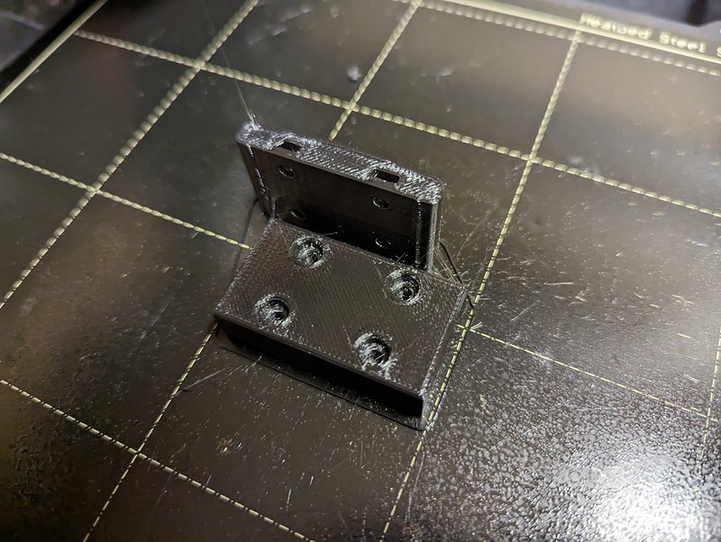 PXL_20230128_185727580 PXL_20230128_185727580 by Timothy Froud, on Flickr  PXL_20230128_192012987 PXL_20230128_192012987 by Timothy Froud, on Flickr The pad is 1mm thick Silicone Rubber sheet.  PXL_20230128_192018365 PXL_20230128_192018365 by Timothy Froud, on Flickr I thought I'd just give it a quick try and see what happens... 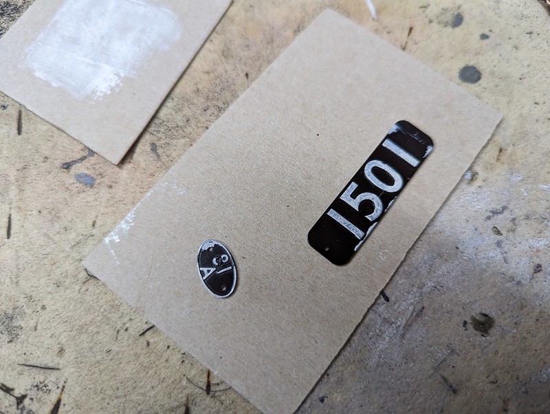 PXL_20230128_204055489 PXL_20230128_204055489 by Timothy Froud, on Flickr ... and again... 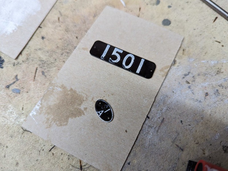 PXL_20230128_204314213 PXL_20230128_204314213 by Timothy Froud, on Flickr ... and again, and that's not going to work. Part of the problem is getting the paint evenly applied, but a more pressing problem is to stop the pad sliding and pushing paint off the edge.  PXL_20230128_204637552 PXL_20230128_204637552 by Timothy Froud, on Flickr Here's another idea...  PXL_20230129_111335432 PXL_20230129_111335432 by Timothy Froud, on Flickr ... which worked a lot better, but still not good enough.  PXL_20230129_111830189 PXL_20230129_111830189 by Timothy Froud, on Flickr However, this is close now. I'll let it go off good and hard and then I can wipe off anything if a second coat doesn't go well. I just held this on a piece of Blu-Tac and dabbed it onto the pad. It didn't touch everywhere but after three gentle dabs it did.  PXL_20230130_203707892 PXL_20230130_203707892 by Timothy Froud, on Flickr This was better, but still nowhere near good enough. I'll give that method another try when the White Spirit has dried. I need to get just the right amount of paint on the pad to transfer enough without going over the edges. It's a tricky one. I don't think I've got a steady enough hand to paint it with a brush, but I might have a go if this doesn't work out. Another thought would be to cover the whole face with Wax and carefully expose the letters, then paint it. How do you do it?  PXL_20230130_203717114 PXL_20230130_203717114 by Timothy Froud, on Flickr Maybe I should use a tiny pad and dab one letter at a time? |
|
mbrown
Elder Statesman
Posts: 1,717
|
Post by mbrown on Jan 30, 2023 22:57:16 GMT
Roger, this is just intuition - I haven't tried it. But I wonder if it would be easier to paint the raised letters and edges white first, not worrying if the paint goes off the top surface, and then fill in the background in black with a tiny brush. My instinct says that it is likely to be easier painting "upwards" along the vertical edges of the letters without getting black on the top surface rather than trying to paint the surface white without it leaking down the sides.
Not sure if that makes sense - and it might not work. Just my two pennorth...
Good luck
Malcolm
|
|
|
|
Post by ilvaporista on Jan 31, 2023 6:54:48 GMT
Roger, this is just intuition - I haven't tried it. But I wonder if it would be easier to paint the raised letters and edges white first, not worrying if the paint goes off the top surface, and then fill in the background in black with a tiny brush. My instinct says that it is likely to be easier painting "upwards" along the vertical edges of the letters without getting black on the top surface rather than trying to paint the surface white without it leaking down the sides. Not sure if that makes sense - and it might not work. Just my two pennorth... Good luck Malcolm I painted the whole plate white first and then sprayed over with black. Whilst the paint was still wet I wiped off the top of the letters with a cotton bud . I was happy with the result. |
|
|
|
Post by dhamblin on Jan 31, 2023 7:53:03 GMT
I agree, paint white first, leave to harden, then paint black and remove from the raised bits using a thin piece of card to wipe over each plate. That's the technique used on model railway etched plates and should work here as you have good depth of raised lettering.
As you've already found with the numberplate the trick will be to not wipe off paint at the ends. Just use a narrow bit of card.
Regards,
Dan
|
|
|
|
Post by Roger on Jan 31, 2023 13:23:37 GMT
Thanks to all, that's what I'll do it the current method is unsuccessful.
|
|


