greensands
Part of the e-furniture
 Building a Don Young 5" Black Five
Posts: 409
|
Post by greensands on Dec 14, 2013 14:18:54 GMT
Hi - Can anyone please help me with the starting arrangements for the AEI AC single phase electric motor shown in the photograph. Details on the manufacturer's plate give: Type BS1507-B; Single phase; Speed range: 1425/1725: BS170. The motor needs to be re-wired as the existing wiring has been laid bare but this can be taken care of. The motor was supplied with the small relay shown in the photo made by Magnetic Devices but there was no sign of any starting capacitor. Any helpful suggestions would be most welcomed. Kind regards Reg 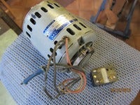 |
|
nonort
Part of the e-furniture
If all the worlds a Stage someone's nicked the Horses
Posts: 277 
|
Post by nonort on Dec 14, 2013 18:09:20 GMT
Ive just googled the first part of the discription BS1507-B. It threw up a link that lost me in seconds talking about winding resistances but you may be able to fathom the electric string out from this.
|
|
|
|
Post by Roger on Dec 14, 2013 19:33:38 GMT
You have four wires, so it looks like you have both ends of both windings there. They should be insulated from each other, and the starting winding will have a higher resistance than the main running one.
The running winding will have live and neutral across it all of the time when it's running. This gives the main drive. Much as a single cylinder steam engine can get stuck on dead centre, so it is with a single phase motor. If you put power as I've indicated on your motor after you've given it a spin, it would keep running in that direction. It would run just as happily in the other direction if you spun it the other way.
The starting winding makes sure that it starts in the right direction, and it's arranged to be at 90 degrees mechanically to the other winding. That allows the motor to behave in a similar way to a steam engine with two cylinders at 90 degrees to each other. The trouble is, you only have a single phase supply that's in the right phase for the running winding. To overcome this problem, a capacitor is added in series with the starting winding. The value of the capacitor is chosen so that the voltage across the starting coil is approximately at 90 degrees to the running winding when it's at 50Hz ie the running speed. Usually there's a centrifugal switch inside the motor that disconnects the starting winding when it gets up to speed. Until you try this, you might not know. You'll hear it click when the motor starts and stops.
I can't see a data sheet to tell you what value the capacitor should be, but you're unlikely to have a problem if you try one off another motor. It doesn't have to be precise. Only use capacitors intended for the purpose though!!!
Some motors do run with the capacitor permanently in circuit, but I doubt if yours is like that.
You can arrange a reversing switch to reverse the polarity of the starting winding. This is ok if the motor has a centrifugal switch but not good for the other type.
I hope that helps.
Roger
|
|
greensands
Part of the e-furniture
Building a Don Young 5" Black Five
Posts: 409
|
Post by greensands on Dec 14, 2013 21:16:33 GMT
Hi Roger - Many thanks for the very useful and informative write up you have provided. I have stripped the motor down as part of the re-wiring exercise and there is no sign of a centrifugal switch which I have seen on the larger type of AEI electric motors of say a 1/2 HP or greater as might be used for driving a Myford lathe. The AEI motor in question is of a smaller design having resilient mounts which would suggests a belt driven application which is what I have in mind for my lathe top-slide mounted drill. Presumably without any form of switching we are talking about a capacitor start and run arrangement in which case what type and size of capacitor should I be looking for?
Kind regards Reg
|
|
|
|
Post by Roger on Dec 15, 2013 9:36:08 GMT
Hi Reg, This is a bit of a puzzle because it looks like you need quite a large capacitance in the start winding to get a good starting torque. If that's not important, then you have to use a motor run capacitor, NOT a starting capacitor. Check out this page and the video and you'll see why. www.temcocontent.com/capacitorfaq.html#start_vs_runYou need a capacitor rated at 400V or above to be safe, don't use anything around 240V, it's not high enough to cope with the peak voltage. I'm trying to find the recommended capacitance value but without much luck. You may have to take a stab in the dark and just try something like this... www.ebay.co.uk/itm/30-UF-450V-ELECTRIC-MOTOR-RUN-CAPACITOR-WITH-LEAD-BOLT-/200623242640?pt=UK_BOI_Electrical_Components_Supplies_ET&hash=item2eb613bd90If the motor runs roughly or gets hot then the value is not close to the value required. I'm sorry I can't be more certain than that, there's no formula that you can apply to these things, the values are selected by the manufacturer. Roger |
|
|
|
Post by Deleted on Dec 15, 2013 16:37:13 GMT
Have a look at this on the ME forum}-------- www.model-engineer.co.uk/forums/postings.asp?th=83783 ---------- Also, have you tried contacting the current inheritors of the AEI name for some help ??------------ I suspect that the resilient mount is more to do with the possibility of not having a capacitor start and thus a large physical "jolt" to absorb when starting ?? |
|
|
|
Post by Deleted on Dec 15, 2013 16:47:21 GMT
|
|
|
|
Post by Roger on Dec 15, 2013 18:57:32 GMT
I don't think you can deduce what capacitor yours should be from another motor. I think you'll have to bite the bullet and experiment with a test value of capacitor. So long as you don't run it for long, I can't see that you'll damage it. Try it for 30 seconds and then see if it's getting hot. Listen to what it sounds like and if it seems ok, extend the running period bit by bit until you're happy that it's running luke warm.
The company has been bought out by GE at some point but I don't think there's much hope of getting any support from their current owners.
|
|
|
|
Post by fostergp6nhp on Dec 15, 2013 20:24:40 GMT
The current owners of AEI is Alstom and that motor is a shaded pole type. The resilient mount is just that and it has nothing to do with starting jolts. The person i knew who could have answered all the questions to do with the connections and capacitance is long dead as it was my grandfather who developed this motor type at BTH Rugby who the predicessors to AEI.
|
|
jackrae
Elder Statesman

Posts: 1,333
|
Post by jackrae on Dec 15, 2013 20:32:01 GMT
I cannot read the HP rating but it looks something like 1/x0 where the larger the value of x the smaller the power rating. If it's less than 1/10th HP its range of use will be extremely limited. Even at 1/10th there won't be many applications if you are considering using it to drive some form of tooled machine.
Because of its open construction I suspect it was originally a ventilation fan motor, relying upon the external fan to provide cooling
The cable ends would appear to be rubber insulated which may show signs of hardened embrittlement. If this is the case I'd suggest you split the casing to ensure internal wiring is OK.
|
|
steam4ian
Elder Statesman
One good turn deserves another
Posts: 2,069
|
Post by steam4ian on Dec 15, 2013 22:15:57 GMT
Greensands.
The motor may not be capacitor start at all but simply two winding start. By arranging that one winding has a high resistance/inductance ratio relative to the other winding the current phase shift described by Roger will occur giving a pseudo rotating magnetic field in the air gap. The relay is some thermal or other time delay device to switch out the starting winding.
Keep playing with it if you must but I would advise a difference course of action.
If you want a tool post drill get hold of a disused battery drill, old 12V units are ideal, and provide a mounting for that. Most times these become available in car boot or garage sales because the batteries have failed. The battery can be replaced by a dc power supply from the mains, if a 12/14V drill then a cheap battery charger will do. Worked for me.
|
|
greensands
Part of the e-furniture
Building a Don Young 5" Black Five
Posts: 409
|
Post by greensands on Dec 16, 2013 18:14:22 GMT
Hi Ian - If this motor is a two winding start does this mean that the two windings are to be connected in parallel across the mains supply or in series?
|
|
|
|
Post by houstonceng on Dec 16, 2013 18:38:39 GMT
Parallel
|
|
greensands
Part of the e-furniture
Building a Don Young 5" Black Five
Posts: 409
|
Post by greensands on Dec 16, 2013 18:48:02 GMT
And how is the relay wired in?
|
|
|
|
Post by Roger on Dec 17, 2013 8:10:42 GMT
Take a look at all the different motor types in this link and see if you can decide which it is. en.wikipedia.org/wiki/AC_motorThe absence of a centrifugal switch tends to indicate that it's intended for an application which requires only a low starting torgue. You can't leave a starting capacitor in circuit for long, and that's needed if you're going to draw a lot of starting current in the starting coils. Excuse my ignorance, but I thought shaded pole motors were those ones that you see driving drain pumps on washing machines or fans on boilers. I've never seen one that looks like yours. I think it's time to just try a run capacitor in series with the high resistance coil. It's much more risky to try it without a capacitor in that coil in my opinion. |
|
greensands
Part of the e-furniture
Building a Don Young 5" Black Five
Posts: 409
|
Post by greensands on Dec 17, 2013 10:05:34 GMT
Hi - Although I am no expert, I do not think that my motor can be a shaded pole type as it does not resemble any of the photos I seen of the type but has all the appearances of a standard squirrel cage design. Having said that, and in the absence of any capacitors which came with the motor I am of the opinion that it could be a split phase design. It came with what I took to be a standard relay but on closer inspection looks as if it might be a thermal relay having a built in resistor and bi-metal switch contact. Presumably this would have been connected in series with the starting winding and designed to switch out when the current through the winding causes the bi-metal to trip the contacts.
Does this sound feasible?
|
|
steam4ian
Elder Statesman
One good turn deserves another
Posts: 2,069
|
Post by steam4ian on Dec 17, 2013 12:09:15 GMT
Greensands, I would be quite certain a motor of that arrangement is not shaded pole. Roger seems fixated on putting a capacitor in the circuit but hasn't advised what value the capacitor should be. At the fractional HP size it is more likely a split winding motor.
The relay could also be an overload. to open the supply circuit. A thermal type relay could provide the time delay for staring; this type of relay is used in single phase bore pumps
You really need to take the motor apart and provide more photos of it and the relay before anybody here can give advice on which you can bet your life or your house, that is what you are risking.
Ian
|
|
|
|
Post by houstonceng on Dec 17, 2013 15:39:35 GMT
The wiring and starting circuits of single phase motors are many and various. With no real information available it would not be sensible without proper experimentation to assume that the motor is or isn't a Capacitor start. For example, many domestic refrigerators, dehumidifier sand similar devices use single phase fractional horsepower motors (SPFHpM) in their compressors of split-phase design started using a small solenoid relay.
The coil of the relay - a few turns of heavy wire - is connected in series with the running winding. The contacts are wired in series with the start winding. On initial application of power, the large inrush current to the run winding operates the relay and connects the start winding long enough to establish the rotation. Once the motor is running, the current in the run winding reduces to a level that can't hold in the relay and the start winding is disconnected. The relay is NOT a thermal delayed device.
The relay you have could be for the above use, or it it could just be part ova homemade no volt release (NVR).
Get a competent motor expert to look at it, or buy something with more info behind it.
|
|
|
|
Post by houstonceng on Dec 17, 2013 15:46:31 GMT
Looking at the picture of your relay, it has three terminals, in common with those 'fridge compressors, so could be for the same purpose.
|
|
greensands
Part of the e-furniture
Building a Don Young 5" Black Five
Posts: 409
|
Post by greensands on Dec 17, 2013 16:01:32 GMT
I take on board the note(s) of caution being expressed in this thread which is appreciated and I will most likely take the general advice given and look for an alternative means of driving my top slide drilling attachment. However, it has become something of an academic exercise to establish just how this motor was designed to be used and to all those who might just still be interested I have attached some further photos showing the dismantled motor and relay. As can be seen, the original wiring has been replaced retaining the same colour scheme except the use of orange in place of yellow. Resistance values are as follows: 12.8R Red/Black and 23R Orange/Blue The relay is made by Magnetic Devices Ltd. of Newmarket. There are three terminals on the back plate numbered 2 to 4, (No.1 left blank). Terminal 2 is marked "P", terminal 3 "M" and terminal 4 "L".   |
|


