|
|
Post by Deleted on Jan 18, 2014 20:50:30 GMT
No MIKE........ I do also wherever possible...It's just a "thing" I have about replicating ALL facets of full size practice whenever I can...eg}--- My workshop is set-out in similar manner to Swindon "A" shop complete with overhead crane, loco screw jacks etc.....Boilers are in a separate area as is the Machine Shop.......Similarly I expect a "Right Away" from my guard when passenger hauling etc...
|
|
|
|
Post by Deleted on Jan 18, 2014 20:55:57 GMT
Thanks BAGGO......I remember the late Ray Tranter at SVR used trammels along the piston rod based from the cylinder face ( Cover removed)...He advised using the ring edge as well..
|
|
pault
Elder Statesman
  
Posts: 1,500
|
Post by pault on Jan 18, 2014 22:54:59 GMT
Hi Mike, no you’re not the only one to use CI pistons, valves liners and clupet (CI) rings I do whenever possible. Roger yes I use compressed air what I do is to put a rubber tube on the drain cock and put it into a cup of water. You only need a couple of PSI in the steam chest and you can see exactly when the valve opens. Yes John, your understanding of “
I've always assumed that the edge of the ring controls the opening of the port as it's the ring that does the actual sealing, not the valve bobbin.” Is correct and is the way full size were done. It is the way I have always made piston valves this way as well
|
|
|
|
Post by Roger on Jan 18, 2014 23:17:01 GMT
It sounds like the dead reckoning method using measurements is a good place to start from what you say. I may well check the opening using the drain cock idea too. I'll take a look at the different PTFEs that are out there, I don't really know what's available these days. I'm convinced that PTFE piston seals are the best option for SPEEDY though, that seems like a simple and effective way to get a really good seal.
|
|
jma1009
Elder Statesman
  
Posts: 5,917
|
Post by jma1009 on Jan 18, 2014 23:30:34 GMT
lets not jump off topic too far - valve setting is quite a specialised and separate subject in my book!
john/baggo's posts are excellent and worthy of close study, as is his website. one of the big problems in miniature is making piston valves that dont 'blow' thereby considerably reducing the effective steam pressure on the piston plus wastage and increased fuel and water consumption, instead of what should be a loco that performs as well if not better than a slide valve loco. in brian's case (DORIS), and john/baggo's case (HELEN LONGISH) there isnt sufficient room to fit proper piston rings.
i would agree with miken that with cast iron cylinders and cast iron piston valves and liners, proper cast iron rings is always going to be the superior way of doing things! (pete, please note re DONCASTER!).
i have always considered the subject of piston valves to be a very important subject in miniature and dont mind how often this topic crops up on the forum. there is nothing worse than driving a piston valve loco in miniature and opening the regulator to get a 'whoosh' from the chimney and no movement of the loco! you might as well take the springs out of the safety valves for the same effect!
cheers,
julian
|
|
jma1009
Elder Statesman
  
Posts: 5,917
|
Post by jma1009 on Jan 19, 2014 1:29:06 GMT
hi brian,
LBSC made piston valves for his own locos in the 1930's 2.5"g and 3.5"g. stainless wasnt available then generally and piston rods were 'german'/nickel silver. i was told never to use stainless with bronze many years ago by a very experienced marine engineer who was president of our club at the time.
if you decide to use solid bobbins of phos bronze make them a very very good fit to start with ie a tight push fit, so turn up a bit of brass to be a tight push fit then 'mike' up and use that as a reference for the bobbins. provide a bit of an allowance for machining marks etc say 1/2" thou depending on the finish and how good your turning is. the maxim with solid type piston valves is that 'piston valves wear out, slide valves wear in'! with solid bobbins in similar metals you want a very very good fit. measure or make separate plug gauges for each end due to the vagaries of the reamer on the liner, though if you've tried stainless bobbins before hopefully all should be ok and any high spots etc and vagaries in the bores already worn a bit to correct parallel and concentricity.
john's PTFE version is well worth trying out depending on how you get on with PB bobbins. there is a lot to be said for lapping the liners as john did, or in my case wrapping some fine (1200 or 1500 grade) wet and dry paper around a wooden dowel as a substitute for john's far more correct method. with proper lapping the lap must always be of softer material than the liners, and very careful choice of the lapping compound (BRASSO metal polish so long as it isnt allowed to dry out is ok).
i would add a few set screws to the liners just for safe measure to secure same. these days we would loctite same but undersize on the bores and then finish with a boring bar between centres (instead of a reamer) to ensure all is to size and concentric and parallel.
personally, i have never quite seen the need for piston valves in miniature with our much reduced working pressure compared to fullsize. in lots of cases following fullsize and the arrangement of the combination lever and radius rod requires piston valves. but otherwise they are a pain and require a lot of skill/hard work/fitting to get right to avoid after the first few steam ups that the valves dont 'blow'.
one has only to read of john/baggo's efforts with same on HELEN LONGISH to realise that piston valves arent easy to get right even in the hands of very experienced model engineers.
i think the larger 5" and above locos arent so awkward, as fullsize practice can be adopted, especially with cast iron cylinders.
anyway that's my thoughts on the subject! do let us know how you get on!
cheers,
julian
|
|
|
|
Post by Deleted on Jan 19, 2014 2:10:44 GMT
Following on from Julian's post above re the simplicity of slide valves versus piston valves, I am sure there is a lot of scope in following the balanced slide valve route. Very little seems to have been done on furthering the advantage of balanced slide valves in reducing the load on the valve gear caused by normal unbalanced valves (You try moving a slide valve by hand when there is air or steam pressure on it!) You've got the best of both worlds - no problems getting the valves to seal and a greatly reduced load on the valve gear with less wear over time. Balancing a conventional slide valve where the exhaust port is in the cylinder block is very easy to do using an O ring on a spigot on top of the valve which seals againgst the valve chest cover. It gets more difficult where the exhaust exits through the valve and through the steam chest cover but is not impossible. I will be using this system on my stretched 0-6-2 Simplex when I finally get back to it, mainly because I've already got the slide valve cylinder castings but also because I fancy giving it a try.
John
|
|
|
|
Post by runner42 on Jan 19, 2014 3:27:18 GMT
Thanks to all that that have added since my last post, particularly John (Baggo) and Julian. There is a lot to digest. I hope Doris' needs have not outgrown my capabilities. What I have assumed to be the way ahead is to lap the bore in the liner, method to be thought about a little further. Produce PTFE bobbins that are a push fit in the liner, thickness of the PTFE to be as thin as possible say 0.062". The piston valve body made of brass(?) and generally in accordance with the below sketch, which is keeping the same key measurements the same as the original. Regards Brian PS John how were the PTFE bobbins produced bearing in mind the thickness is only 0.062". I assume it was fitted to an appropriate sized mandrel and the OD finished this way? Attachments:
|
|
|
|
Post by Roger on Jan 19, 2014 7:51:33 GMT
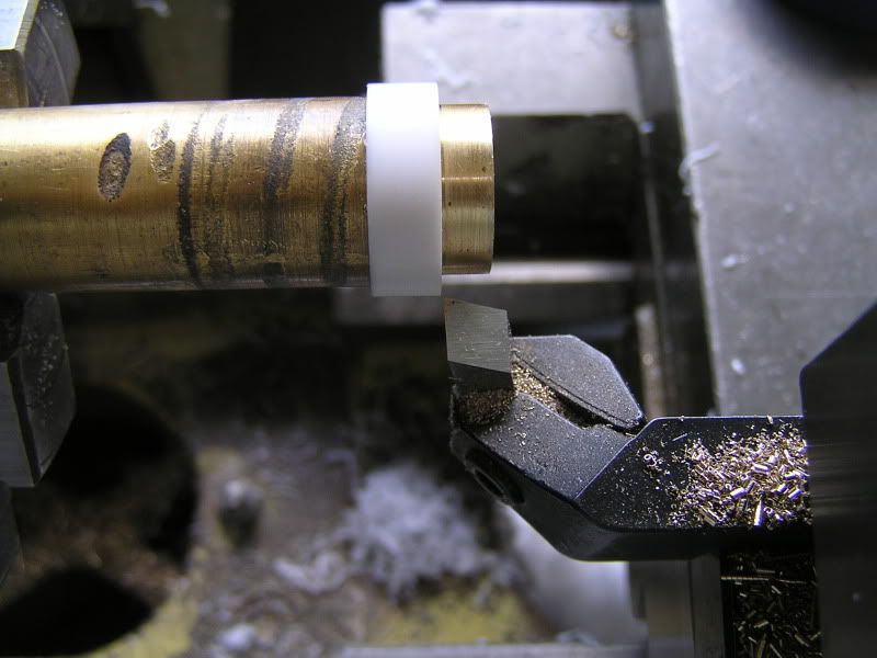
In my experience, PTFE needs to be turned with the sharpest of tools, don't try to use Carbide Insert types, you won't be able to take a fine enough cut when you get near to the finished size. I'd grind up a HSS tool with plenty of clearance and top rake. It doesn't matter that the tip won't be very strong because the cutting forces are small. The idea is to apply the cutting force through a small area so that the tool penetrates the material rather than sliding over the surface which is its preference. Use the finest feed and very small cuts indeed as you approach the final size and you ought to be able to remove what looks like dust if you get the setup right. If you don't get it right, the tool won't remove any material for several tiny cuts and then take it all in one go, not what you're looking for at all!
|
|
|
|
Post by Deleted on Jan 19, 2014 17:54:53 GMT
Hi Brian, Sorry for the late reply - been at the club today for public running. The method I used for turning the PTFE sleeves is described part way down this page: Machining PTFE sleevesPretty much as you suggested. As Roger says, use nice sharp tools and you can shave tenths off if necessary. PTFE is really nice stuff to machine. John |
|
pault
Elder Statesman
  
Posts: 1,500
|
Post by pault on Jan 19, 2014 17:59:55 GMT
Just don't smoke while you are machining it
Regards
Paul
|
|
|
|
Post by Deleted on Jan 19, 2014 18:40:23 GMT
Good point Paul. Some folks may not know that.
John
|
|
|
|
Post by Roger on Jan 19, 2014 20:44:50 GMT
Hi Brian, Sorry for the late reply - been at the club today for public running. The method I used for turning the PTFE sleeves is described part way down this page: Machining PTFE sleevesPretty much as you suggested. As Roger says, use nice sharp tools and you can shave tenths off if necessary. PTFE is really nice stuff to machine. John I'm enjoying reading through your detailed log about Helen, there's a lot of really useful ideas in there. Roger |
|
|
|
Post by runner42 on Jan 19, 2014 21:16:30 GMT
Thanks John and Roger for the machining PTFE advice. Can the same easing technique described by Justin be used, i.e MSD applied and forced through the liner until a sliding fit is achieved?
Thanks Paul for the non smoking tip. I don't smoke but I sometimes fume.
Brian
|
|
|
|
Post by runner42 on Jan 19, 2014 21:52:12 GMT
This is a bit of change of tack, yet again.
It was mentioned in this post that the piston valve at some position would cover both inlet ports. I have referred to a Walschaerts simulator program and noted that for the piston valve, the distance between the outside of the bobbins is the same as the distance between the outside of the inlet ports. However LBSC design for Doris valve gear, the distance between the bobbins is 1 31/64" whereas the distance between the outside of the inlet ports is 1 1/2", a 1/64" difference. Is this inbuilt lead or something else?
Brian
|
|
|
|
Post by Deleted on Jan 19, 2014 22:15:00 GMT
Hi Brian,
the 1/64" difference is known as exhaust lap or exhaust clearance. When the valve is in the mid position, both ports will be open to exhaust by 1/128". LBSC was very fond of exhaust lap as the theory was that it gives a freer running engine by reducing the compression that normally occurs at the end of the piston stroke. The exhaust lap causes the port to close to exhaust later than normal. Very few 'modern' designers use it as the excess compression is usually caused by poorly designed valve gear so can be avoided by correct design rather than altering the valve.
Re the PTFE sleeve - I don't think there would be any advantage in using the MDS approach. A good push fit should be fine. You could coat the valve when you first fit it as the MDS will coat the valve liner and help lubrication.
John
|
|
|
|
Post by Jim on Jan 19, 2014 22:28:28 GMT
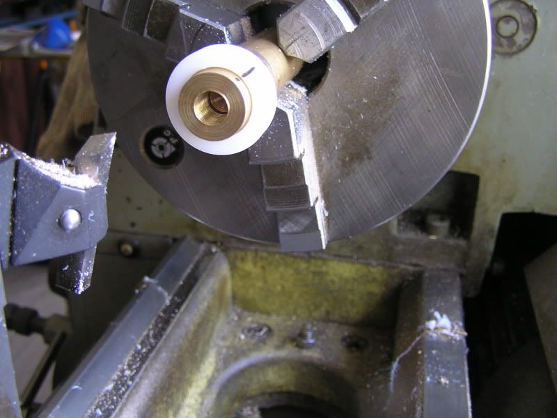
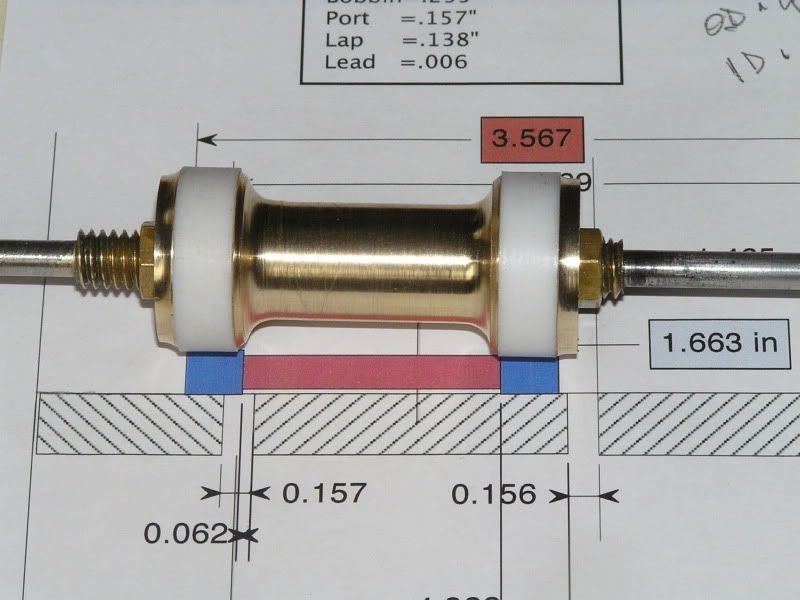
In answer to Brian's question re mandrels for machining the PTFE valves this is the quickie mandrel I used. The mark on the PTFE matched to one on the mandrel was to check that the PTFE hadn't moved during turning. The second photo shows the HSS cutting tool essential as Striplar says for cutting PTFE. In this case it's the very handy tangential cutter I use pretty well all the time on the lathe. The final photo shows the completed valve with the retaining caps relieved to ensure the edge of the PTFE controls the ports, not sure that that's the right term. Hope this helps. Jim    |
|
|
|
Post by Roger on Jan 20, 2014 6:57:42 GMT
Hi Jim,
Those PTFE rings look a lot thicker than the ones described by John, what's the clearance between the inside diameter and the bobbin? John describes the problems he had with expansion and that's why the PTFE sleeves he had were so thin. Maybe yours being shorter means it's not quite such a problem. Anyway, I'm inclined to make mine with a slightly larger inside diameter than yours appear to be since there's no real penalty that I can see in doing that.
Roger
|
|
|
|
Post by runner42 on Jan 20, 2014 7:40:05 GMT
Thanks John, 'lap' was a confusing term to me until I realised that it is was a shortened version of 'overlap' and indicates how much the piston valve overlaps the appropriate steam inlet port.
Thanks Jim, the marking of the PTFE liner and the mandrel to see that the PTFE hasn't moved during machining does raise a further question. Obviously the PTFE internal diameter has to be tight fit on the mandrel to enable machining to take place, but can it be too tight such that it stretches the PTFE and after machining the OD and removing it from the mandrel that it returns to its original state, but with the OD slightly less than expected. This assumes that PTFE has some elasticity. If it doesn't it's a stupid question.
Brian
|
|
|
|
Post by Jim on Jan 20, 2014 7:47:58 GMT
Sorry Roger and Brian if I misled either of you.
The photos were meant as illustrations of the process not the finished product. My PTFE piston rings are based on detailed article in Australian Model Engineering (p13 Mar-Apr 1996). The finished rings are no thicker than .093" for a 1" bore", they have no side clearance but do have .003" clearance on the diameter of the bobbin and are machined with fine cuts to be neat fit in the liner ie, to quote the article, "can be pushed in with the thumbs with very little resistance."
This is a method that has been used successfully on a number of locos here but as with many things in the hobby it's only one of a number of methods.
Jim
|
|