|
|
Post by Rob on Oct 18, 2014 23:02:57 GMT
Hello all, Well, I thought that rather than cluttering up Roger's thread with my postings, I should start my own. So here it is  . First, a little background. I started out in "model engineering" at about the age of 11 or 12 (I put the term in brackets because at that age, there wasn't so much engineering as hacksaw and file wielding!). I was in school, in a technical drawing class with a Mr Morgan, an 'old school' teacher. I had shown some ability in technical drawing, and I thoroughly enjoyed it, so he gave me extra work to do. As I enjoyed the work and he was giving me extra attention we often talked. I don't recall how the conversation started, but it transpired he was interested in O gauge models such as Basset Lowke, etc. He suggested to me that I should go down to the local model engineering club and see if it interested me. I'm glad he did, because I did find it very interesting! I was looking for a model to start out with, and everyone suggested the Sweet Pea. I'm not a great fan of narrow gauge, but I followed the recommendation of the members and duly spent my free time (and lunch times, in school, in Mr Morgan's workshops) building the frames and pony truck. Unfortunately, I didn't have any money, or any machine tools at home, so I got about as far as a set of frames and stretchers, and that was about it. A few years later, cars came along, and that was it for me and model engineering! Fast forward to 2009/10 ish, and I felt like having another bash at this model engineering lark. I didn't really have the enthusiasm to finish the Sweet Pea, so I set my sights on something standard gauge. I wanted it to be fairly small, but at least 0-6-0. I opted for LBSC's Speedy design, because I liked the look of the loco and as it turned out there was a local connection, with the full size loco, numbers 1506-09, being based at Newport, where I grew up and currently live. I still didn't have any machine tools, but thanks to my interest in cars I had myself a large garage with plenty of room... Anyway. Enough waffle, everyone likes to see some pictures, and I do have a few, of what little progress I've made in the last 4 or 5 years! Cheers, Rob |
|
|
|
Post by Rob on Oct 18, 2014 23:13:47 GMT
I ordered a set of drawings, and some frame steel from Reeves, and set to work with my trusty hacksaw and file and ended up with these: 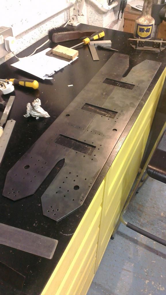 This is actually a much more recent photo as I seem to have misplaced my original ones. The holes for the hornblocks are drilled here, but in reality the position of these is not given on the drawings, so I did not drill them when I originally made the frames. I'm missing a number of other holes too, I shall have to add these in! I also made the buffer beams to the drawings, and as a result I had a set of frames! Fantastic  ! Progress then stopped  . Another year or so passed, and I started getting that itch again... I started looking at Ebay, which is never a good idea at the best of times, and it wasn't long before I was bidding on Myford ML7s. Eventually I managed to win one, and I duly set about getting it back and set up in the workshop. It wasn't perfect, several things were broken, bent or missing, but after a good reaming from Myford (me, not the lathe!) I got it back to working condition! It was at this point I ordered my first set of castings, the hornblocks from Blackgates, as they were considerably cheaper than what Reeves wanted. I also ordered a vertical slide for the Myford and set about making a mess! 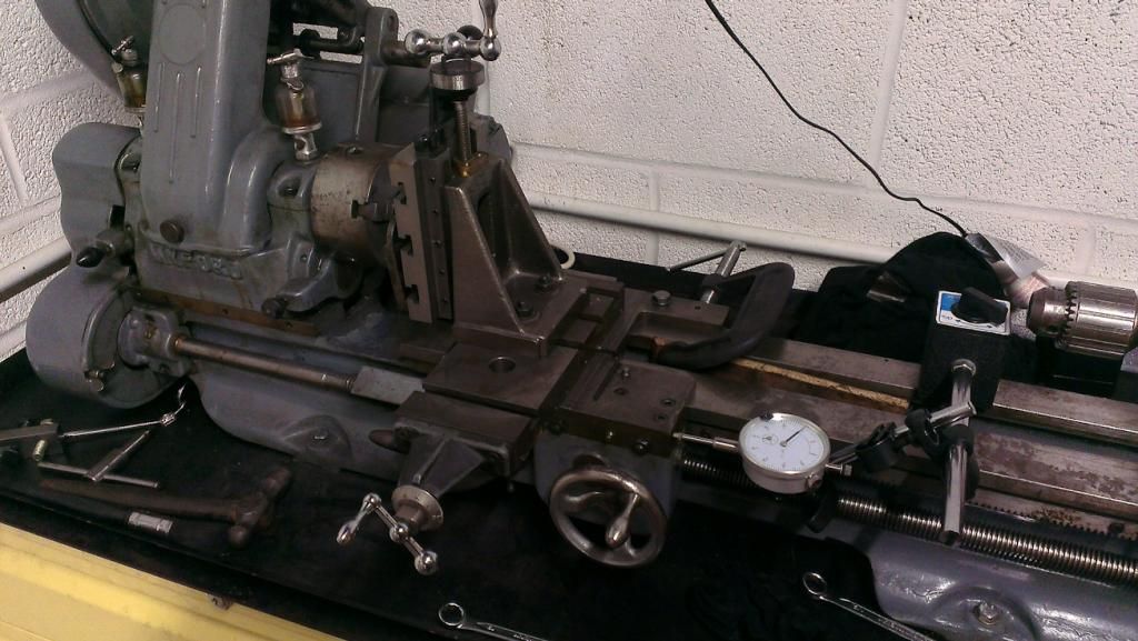 This was my general set up - I moved the DTI around the various axis when I was adjusting cuts as I don't trust my dials (or my leadscrews!). Note the G clamp in the back to help minimise movement. Another view from the front of progress with one of the hornblocks: 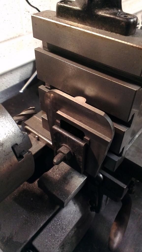 |
|
|
|
Post by Rob on Oct 18, 2014 23:28:57 GMT
The setup in the Myford was painfully slow. I couldn't take much more than 3 thou cuts at the depth you see in the photos in my previous post, or things started to vibrate badly. I also managed to scrap my first casting when something moved somewhere, and my cut went all over the place! I soldiered on with the Myford set up a little longer spending about a week on each hornblock until it got too cold for me to get my motivation up to go out to the workshop. Progress stopped again! It's a recurring theme, isn't it! Fast forward another few years, to the beginning of this one. I decided enough was enough, I was going to get on with my engine, and I was going to treat myself to a mill! Did lots of research, and settled on a Warco. Luckily for me, the Warco open day was approaching, so when it arrived off I trotted with a wadge of cash hoping to bring one back the same day. It wasn't to be, the warehouse was full of chaps drinking tea and eating lunch, so I had to have it delivered. Anyway. After much wrestling, and plenty of help from my father, brother and a friend, we got the mill into position: 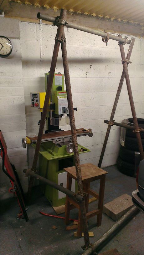 I had already decided I wanted a DRO, but Warco wanted quite a bit extra for one to be fitted, and I had done my research before hand and knew that there were some good deals out there to be had. So ordered my own, and went about fitting it. That was a right pain the arse, the WM18 is very cramped and there was an awful lot to squeeze in. I milled all of the mounting brackets from aluminium. I do have lots of photos of this, but I won't post them here unless they're of interest to someone! When the work was completed, I ended up with something that looks a bit like this: 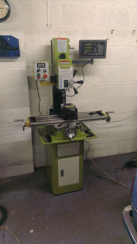 Though the eagle eyed among you will spot that everything reads zero, and there are no scales fitted. It was just a test run of the display! After spending several months off and on working on the machines themselves, I decided I wanted to actually use the machines for the reason that I bought them, to make some progress on my engine! 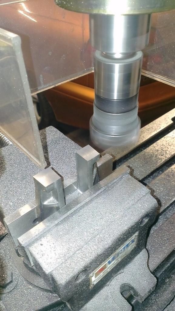 After using the ML7 with a vertical slide, it was pure heaven! I could take decent sized cuts with ease! The rest of the hornblocks were finished up pretty sharpish, I think I managed to do them all in the same time it would take to finish a single side using the ML7! 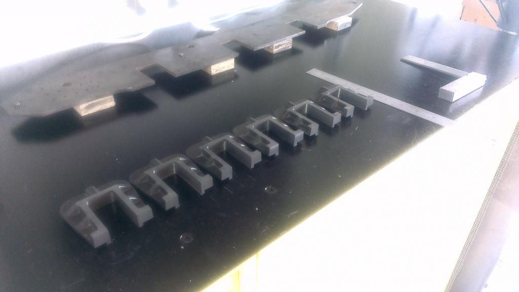 |
|
|
|
Post by springcrocus on Oct 18, 2014 23:32:21 GMT
... First, I was in school, in a technical drawing class with a Mr Morgan, an 'old school' teacher. I had shown some ability in technical drawing, and I thoroughly enjoyed it, so he gave me extra work to do. As I enjoyed the work and he was giving me extra attention we often talked. I don't recall how the conversation started, but it transpired he was interested in O gauge models such as Basset Lowke, etc. He suggested to me that I should go down to the local model engineering club and see if it interested me. Rob ... Hi, Rob You are obviously referring to the "good old days" when teachers actually taught, and took an interest in their pupils and their development. My apologies for my jaded opinion of the teachers of today, I am sure that many of you do much the same as Mr Morgan, but I have seen too many instances of where the "career" has become "a job" and self-interest rules. I hope that your revitalised interest in (model) engineering gives you much pleasure in the future. There are many definitions of an engineer but one of my favourites is "someone who can piece of junk into something useful". This , obviously, includes raw material. Don't worry too much about the end product, but make sure that you enjoy the journey. Steve |
|
|
|
Post by Rob on Oct 18, 2014 23:37:48 GMT
Somewhere in between buying the mill and fitting the DRO, I decided to make some progress on something I could do whilst the mill was out of commission, so I started work on the eccentrics: 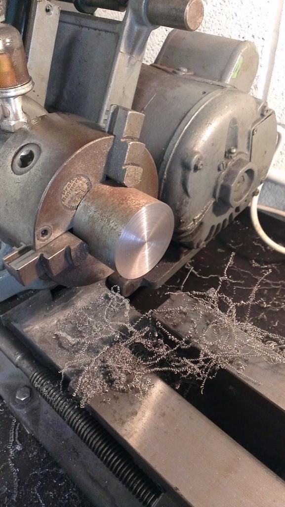 Grooves formed, work progressed on the boss: 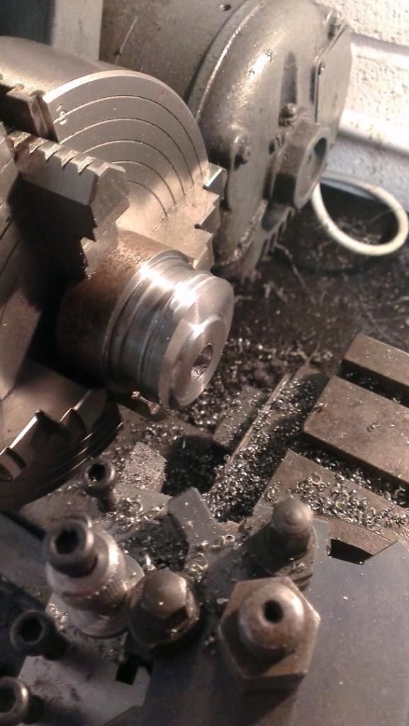 Boring out the hole for the axle: 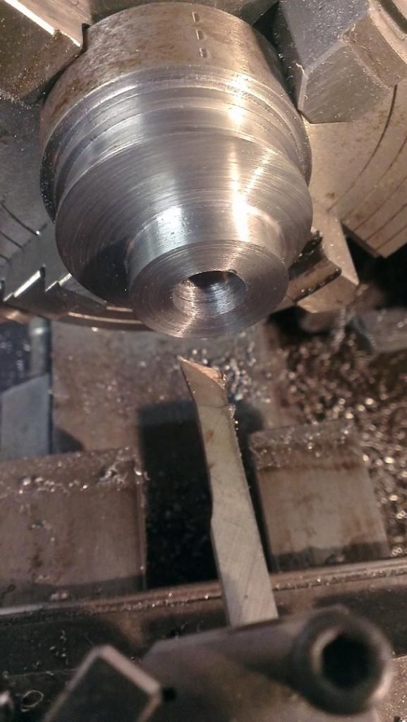 Almost there! 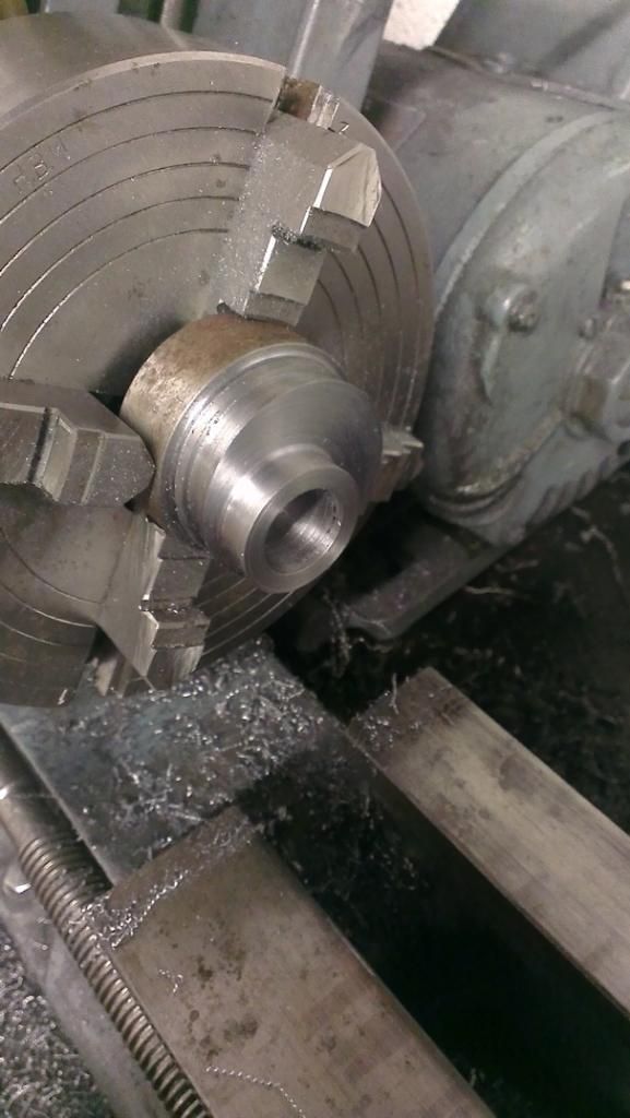 Cleaning up the back face using an expanding mandrel: 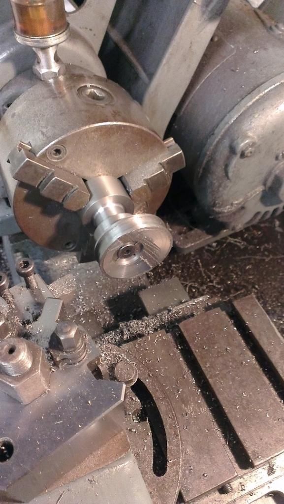 The larger of the two eccentrics was a little too much weight to be off center in my little Myford, so I used the offcut from the previous one as a counter balance: 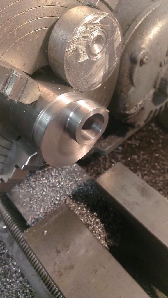 All finished! 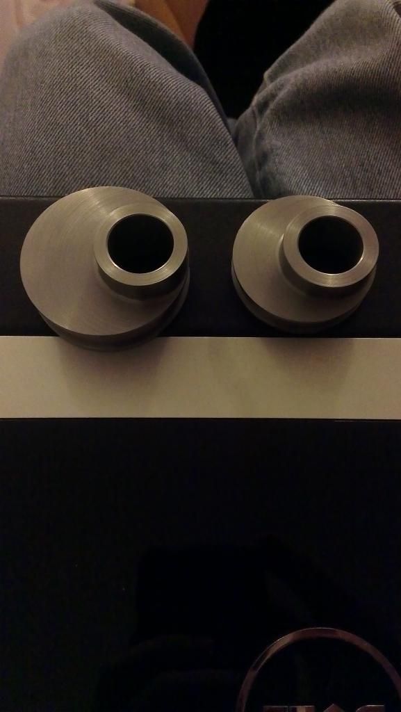 Well, almost, they do need drilled and tapped holes for a set screw, but I'll do those when the axles are ready to receive them! |
|
|
|
Post by Rob on Oct 18, 2014 23:42:46 GMT
Once the DRO was sorted for the mill, the focus returned to the frames. The hornblocks were finally riveted in, about 2 or 3 years after I first started machining them! 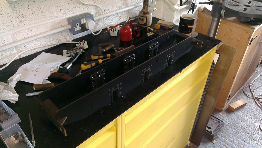 I used the mill to get the blocks nearer to size in the frames, as they had been left proud. Good opportunity to remove the bulk of the mashed rivets too, my riveting isn't too clever! 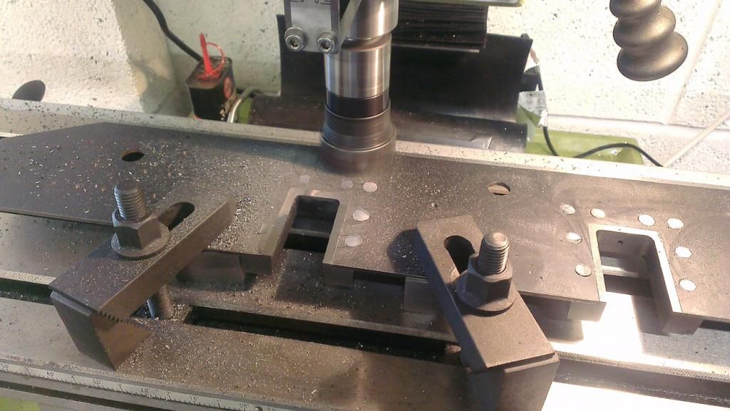 The hornblocks and rivets were then filed flush by hand. |
|
|
|
Post by Rob on Oct 18, 2014 23:54:00 GMT
We're now almost up to date! I machined the pump stay which promptly assumed the attitude and appearance of a banana. I also struggled with finish, and thanks to help and advice from members here I tried again using slower speeds and things improved no end: 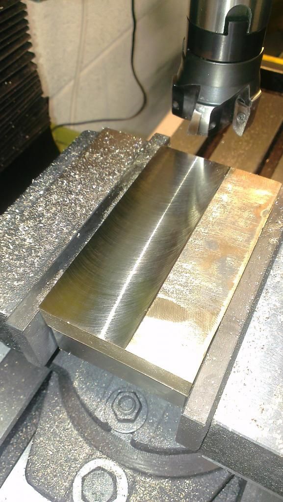 I also parted with some cash, and in return got some lovely lumps of metal: 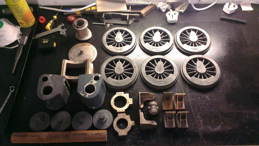 I was expecting a boss on the rear of the wheels, but they were flat: 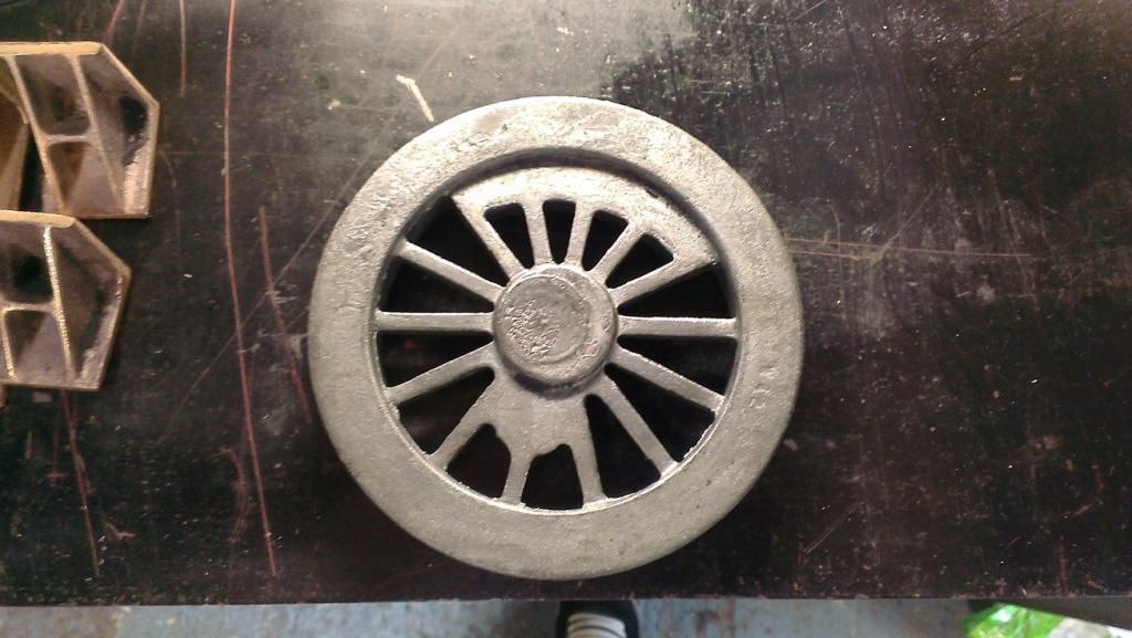 So I guess I'm going to have to drill the axle mounting hole and mount them on an expanding mandrel to rough them, before finishing them up mounted to the axles. I had thought about making the cylinder castings out of solid, but in the end the price was so reasonable from Blackgates I decided it just wasn't worth it. You get the cylinders, the covers and material for the linings all for about 50 quid per side. Not bad, in my opinion! However! When I inspected the cylinder castings, I was a little shocked to find this: 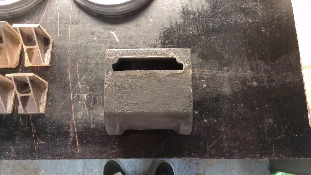 This wasn't what I was expecting at all! I'm a little concerned about this, and am looking for advice. Coming from the car world, I think what's going to happen to the exhaust steam with these cylinders as they are is bad. The steam is going to exit the cylinder, expand to fill the void, and then be forced up a small blast pipe causing all sorts of problems with flow. Ideally, the exhaust should start narrow and get bigger as it goes, not go from narrow to big to narrow again. My question, is this worth worrying about? Has anyone else come across this style of exhaust before? Am I missing something obvious? |
|
|
|
Post by Rob on Oct 19, 2014 0:09:40 GMT
Hi, Rob You are obviously referring to the "good old days" when teachers actually taught, and took an interest in their pupils and their development. My apologies for my jaded opinion of the teachers of today, I am sure that many of you do much the same as Mr Morgan, but I have seen too many instances of where the "career" has become "a job" and self-interest rules. I hope that your revitalised interest in (model) engineering gives you much pleasure in the future. There are many definitions of an engineer but one of my favourites is "someone who can piece of junk into something useful". This , obviously, includes raw material. Don't worry too much about the end product, but make sure that you enjoy the journey. Steve Evening (or rather morning!) Steve, Yes, Mr Morgan was definitely someone who took an interest in what he taught. He struck me as someone who had been worn down by disinterested and undisciplined kids, so I think he was pleased when I showed up fresh faced and with enthusiasm. He was approaching retirement age back then, and unfortunately in my opinion he was being treated rather badly by the school in that most of his classes were being or had been phased out. He had a full metalworking workshop in addition to a 'theory' classroom, but the workshop rarely got used by that point. His machines were about to be sold off at auction, though that didn't happen until a few years later. He lost his classrooms altogether in the end, to be replaced by music class rooms. (A respectable class too, but I didn't think it was fair at the time, nor do I think it so now). I am only a young'un, just about clinging on to the right side of 30, but I caught the tale end of classes such as Mr Morgan's, before things moved more towards graphical art rather than technical drawing and metal working. It would surprise me if health and safety didn't play a part in it! My renewed interest is already giving me pleasure, as does reading through the build threads of many members here. I am looking forward to the end product, but as you say I am enjoying (and learning a great deal!) from the journey so far. Cheers, Rob |
|
|
|
Post by Roger on Oct 19, 2014 7:37:12 GMT
... First, I was in school, in a technical drawing class with a Mr Morgan, an 'old school' teacher. I had shown some ability in technical drawing, and I thoroughly enjoyed it, so he gave me extra work to do. As I enjoyed the work and he was giving me extra attention we often talked. I don't recall how the conversation started, but it transpired he was interested in O gauge models such as Basset Lowke, etc. He suggested to me that I should go down to the local model engineering club and see if it interested me. Rob ... Hi, Rob You are obviously referring to the "good old days" when teachers actually taught, and took an interest in their pupils and their development. My apologies for my jaded opinion of the teachers of today, I am sure that many of you do much the same as Mr Morgan, but I have seen too many instances of where the "career" has become "a job" and self-interest rules. I hope that your revitalised interest in (model) engineering gives you much pleasure in the future. There are many definitions of an engineer but one of my favourites is "someone who can piece of junk into something useful". This , obviously, includes raw material. Don't worry too much about the end product, but make sure that you enjoy the journey. Steve Although I agree in part, the problem is that you can't take that sort of interest in a pupil today, it would be seen as 'grooming'. My wife was a teaching assistant for years and you daren't be alone with a pupil and anything personal interaction, such as medical treatment had to be witnessed by another member of staff. This is as much about the protection of the staff as it is the pupils. I too was given extra attention, and went to the Technical Drawing Master's house where he had a fine model beam engine and a part built light aircraft in his workshop. He'd be sacked if he'd done that today. It's a bit sad really. |
|
|
|
Post by Roger on Oct 19, 2014 7:42:51 GMT
Have a chat with Julian about the castings, I think you'll find that it's preferable to what you suggest. I think the logic behind it is to allow the steam to get out of the very restricted passages from the cylinder bore as quickly as possible with the least back pressure. It only acts to smooth out the impulses so presumably you get less 'bark' from the exhaust with that arrangement. I'm going to have to make my mind up very soon about this because I'm at that stage now. Update.... this is what I've decided to do, so if you're is wrong, so is mine!  Exhaust port details Exhaust port details by rogerfroud, on Flickr |
|
|
|
Post by ejparrott on Oct 19, 2014 8:18:24 GMT
Exhaust passageways need to be as large and free flowing as possible from the ports all the way to the blast nozzle. They most certainly don't want to be getting smaller at any point
|
|
Tony K
Elder Statesman

Posts: 1,573
|
Post by Tony K on Oct 19, 2014 8:31:44 GMT
.....I too was given extra attention, and went to the Technical Drawing Master's house where he had a fine model beam engine and a part built light aircraft in his workshop. He'd be sacked if he'd done that today. It's a bit sad really. I understand what you are saying Roger and why you are saying it, but I disagree - well slightly anyway. You could do it but you would have to do it whilst considering the issues and reducing risk e.g. have someone else there or something, make it known what you are doing (and what you are not!), inform parents etc. It applies at clubs with vulnerable people, but as long as people are aware of the issues and address them, the tutoring, mentoring etc. can carry on as it always did. I think people over-react and think "Oh well, too difficult - I won't do it then," - a bit like safety issues and why we finish up with a video of a bonfire on Nov 5. Meanwhile, back at the mill. That looks like an expensive facemill/multi-cutter there - is it a Sandvik? How does it go? |
|
|
|
Post by Rob on Oct 19, 2014 10:35:54 GMT
Have a chat with Julian about the castings, I think you'll find that it's preferable to what you suggest. I think the logic behind it is to allow the steam to get out of the very restricted passages from the cylinder bore as quickly as possible with the least back pressure. It only acts to smooth out the impulses so presumably you get less 'bark' from the exhaust with that arrangement. I'm going to have to make my mind up very soon about this because I'm at that stage now. I don't think so Roger, this arrangement would actually slow the exit of the exhaust and reduce power - the first stroke may be easier as the void fills, but each subsequent one has to deal with the slow moving exhaust still in the void of the cylinder, attempting to travel up the 1/2" blast pipe. Cross sectional changes in exhausts are bad enough, and the transitions should be as smooth as possible when this happens (think port matching on car cylinder heads), but with this huge void, I can't see it being very efficient at all. Reduced exhaust velocity/flow would have an effect on the abilities of the blast nozzle, too, though how much of one I don't know. If I were designing this, I would follow the same principle as a good car exhaust. Each passageway from the bore of the cylinder would be of equal diameter and length and shape (round!), and once they reach the frames and merge with the blast pipe, the bore would increase, with the transitions smoothed, no sharp edges. Even with this set up, the velocity of the exhaust will slow once it reaches the larger diameter. Exhaust passageways need to be as large and free flowing as possible from the ports all the way to the blast nozzle. They most certainly don't want to be getting smaller at any point Exactly, but will this cause enough of an issue to worry about it? I wouldn't do it on a car as it would sap a great deal of power, but as I have no experience of steam engine exhausts I don't know if the detrimental effects are big enough to bother finding a solution. Meanwhile, back at the mill. That looks like an expensive facemill/multi-cutter there - is it a Sandvik? How does it go? I'm not actually sure what it is, I shall have a look when I get out to the workshop later. I was very lucky with it, a friend saved it from the bin for me from a commercial operation. It had been crashed, damaged, written off and replaced, but with a little love and attention and some new bits and pieces, it was made usable again. As for how it goes, for me at least, it goes very well. I'm not experienced enough to pass judgement between it and another cutter, but it does well enough for me . |
|
|
|
Post by Rob on Oct 19, 2014 10:48:07 GMT
If I were you, I'd do away with the slot altogether, and extend those holes to the middle - you can then remove the middle section between the two holes for a slightly bigger passageway. However, if you do need that slot in the back for other reasons, I'd make it the same depth as the inner diameter of the holes to reduce the size of the transition (or make it the same cross sectional area as the blast pipe inner diameter, and smooth out the cross section transitions), I'd also attempt to reduce the space you have behind the ports. But, my disclaimer is that all of my thinking is from internal combustion, so I could well be worrying about it all for nothing! |
|
|
|
Post by Roger on Oct 19, 2014 11:54:43 GMT
I know what you're saying, but I think you'll find it's a very different medium to exhaust gasses in internal combustion engines. The problem you have here is that you want a small volume between the piston at TDC including the exhaust passages to the valves. That's where the trouble lies, getting the lower pressure exhaust back out of those passage ways which are really too small. Allowing the exhaust to expand to the lowest possible pressure as soon as you can appears to be the way to achieve this. If you look at some of the photos people kindly posted on the thread a while back, you can see that the consensus appears to be to provide as much port area and volume behind those as possible.
If you have a narrow channel all the way to the blast pipe, you're going to get a lot more back pressure at the point where the valve first opens. If you allow the rapid initial expansion to take place into a larger volume, it can then dissipate through the blast pipe at its leisure.
I don't have any experience of this, I'm just taking on board what those have said who've been in this game for years.
|
|
|
|
Post by Deleted on Oct 19, 2014 18:46:39 GMT
Remember also that Rogers good image is showing your cavity joining up to the exhaust port at the R/H end only, whereas in reality there are ports at BOTH ends ( because its'a double-acting cylinder ) so those exhaust gasses will only be travelling along HALF of the cavity width before discharging through the frame and into the exhaust pipe / nozzle............Perhaps a bit of profile changing with a ball-nosed cutter at the bottom so you get a minimal of profile shape change ?.....Keep the cross-sectional area as near to those two holes already shown and blend-in the inner edges ( those nearest the centre ) to help promote good flow.......Don't worry, your exhaust will be doing quite enough expansion as it exits up through the petticoat pipe and taper chimney liner ..... Incidentally the last thing any Fireman wants for all his efforts is that huge, emotive "Bark" of an exhaust every 90 degrees ( or whatever is the case)---- Why ?, because it rips up his carefully made fire bed and can ---in some cases--- send red-hot coals out of the chimney...NOT FUNNY during hot Summers when the line-side grass or Farmers fields catch fire.....What's needed is a CONTINIOUS, low velocity ( by comparison I mean ) blast that increases lineally with increase of track speed.......... Just for interest sake but the wheel balancer at Swindon showed its' top rotational speed at somewhere around the 200 to 250 mark..........Do a quick maths session and work out the RPMs' for Speedy's drivers at say 4 mph ( Brisk walking pace---- Recommended operating speed for battery-electrics etc..)----
|
|
|
|
Post by Rob on Oct 19, 2014 23:29:17 GMT
Meanwhile, back at the mill. That looks like an expensive facemill/multi-cutter there - is it a Sandvik? How does it go? I had a look at the cutter, but it has no manufacturer's name written on it, so I don't think it's Sandvik as all the images I can find on the net show the name clearly etched in the cutter. Remember also that Rogers good image is showing your cavity joining up to the exhaust port at the R/H end only, whereas in reality there are ports at BOTH ends ( because its'a double-acting cylinder ) so those exhaust gasses will only be travelling along HALF of the cavity width before discharging through the frame and into the exhaust pipe / nozzle............Perhaps a bit of profile changing with a ball-nosed cutter at the bottom so you get a minimal of profile shape change ?.....Keep the cross-sectional area as near to those two holes already shown and blend-in the inner edges ( those nearest the centre ) to help promote good flow.......Don't worry, your exhaust will be doing quite enough expansion as it exits up through the petticoat pipe and taper chimney liner ..... Incidentally the last thing any Fireman wants for all his efforts is that huge, emotive "Bark" of an exhaust every 90 degrees ( or whatever is the case)---- Why ?, because it rips up his carefully made fire bed and can ---in some cases--- send red-hot coals out of the chimney...NOT FUNNY during hot Summers when the line-side grass or Farmers fields catch fire.....What's needed is a CONTINIOUS, low velocity ( by comparison I mean ) blast that increases lineally with increase of track speed.......... Just for interest sake but the wheel balancer at Swindon showed its' top rotational speed at somewhere around the 200 to 250 mark..........Do a quick maths session and work out the RPMs' for Speedy's drivers at say 4 mph ( Brisk walking pace---- Recommended operating speed for battery-electrics etc..)---- At 4 MPH, unless my maths has failed me, I work it out to be about 272 RPM, which equates to 1089 exhaust beats per minute, or 18 a second. It's no wonder 5" gauge locos sound like machine guns! Roger's design will prove to be more efficient than with what I have with my castings, as the void in mine is much larger than the slot shown, but perhaps I should just see what happens with it! I'm just about geared up to open up the hornblocks to size now, tomorrow will be working out how best to clamp the frames to the table. |
|
|
|
Post by Deleted on Oct 20, 2014 0:31:31 GMT
Agreed, 18 beats per second COLLECTIVELY that is ( as heard at the chimney, for example ) but divide that by 4 to get event cycles per port----- which gives >>>>>>>>>>> 4.5 exhaust discharges per second.........Indeed it's 272 working cycles of ALL the trains wheels and any associated items.....( By-pass pump or valve movements for instance..)..... So that's 4.5 per second...............try setting this metronome at 60 beats per min to "Hear" what one second sounds like >>>>>>>>>>>>> www.online-stopwatch.com/metronome/ ---------- |
|
|
|
Post by ejparrott on Oct 20, 2014 8:05:49 GMT
The inserts look like APKT 16, could be Mitsubishi Walter or Tageutec
|
|
|
|
Post by Roger on Oct 20, 2014 8:25:15 GMT
Roger's design will prove to be more efficient than with what I have with my castings, as the void in mine is much larger than the slot shown, but perhaps I should just see what happens with it! I don't think there's any way you can deduce what will work better, all we have is the combined experience of other modellers to go on. The attraction for me in doing it this way is the ease of manufacture, particularly when it comes to opening out the exhaust passages from two holes. Whatever you choose to do, it's going to work anyway so we're probably splitting hairs. What's the worst that can happen? The only down side I can see is that there's steam in contact with the frame, but I might cover everything except the hole with the thin gasket material I bought for the purpose. |
|


 .
. ! Progress then stopped
  .
. 


