|
|
Post by Roger on Jun 28, 2018 11:14:17 GMT
Hi Steve,
Your thread is a great source of ideas and methods that are applicable to every builder, that's why we keep looking.
One thing I quickly realised is that people will only read a few lines before moving on. Big blocks of text just don't get read so it's a waste of time writing too much, unless you enjoy doing it. Pictures are by far the most useful from the point of view of seeing progress and how it was done. These days I think in terms of photographs with just enough text to make sense of them.
Occasionally a discussion make things more text based, but on the whole, pictures rule. I think you strike the right balance when it comes to that.
|
|
|
|
Post by springcrocus on Jun 29, 2018 7:28:07 GMT
So there was I, enjoying a nice little wallow in self-pity and having a really good sulk after the last small forum spat, and then you guys go and spoil it all by being so nice! I don't know what this place is coming to.  I suppose I'd better get back in the workshop, then, and start writing up my jobs again and will try to have something ready before the weekend is over. Oh, and apologies to those who thought I'd gone for good - better luck next time, hey?  Regards, Steve |
|
|
|
Post by simplyloco on Jun 29, 2018 7:39:17 GMT
So there was I, enjoying a nice little wallow in self-pity and having a really good sulk after the last small forum spat, and then you guys go and spoil it all by being so nice! I don't know what this place is coming to. I suppose I'd better get back in the workshop, then, and start writing up my jobs again and will try to have something ready before the weekend is over. Oh, and apologies to those who thought I'd gone for good - better luck next time, hey? Regards, Steve You won't have time if you are coming over to our 3 1/2" day tomorrow! John |
|
|
|
Post by Cro on Jun 29, 2018 7:42:43 GMT
So there was I, enjoying a nice little wallow in self-pity and having a really good sulk after the last small forum spat, and then you guys go and spoil it all by being so nice! I don't know what this place is coming to. I suppose I'd better get back in the workshop, then, and start writing up my jobs again and will try to have something ready before the weekend is over. Oh, and apologies to those who thought I'd gone for good - better luck next time, hey? Regards, Steve You won't have time if you are coming over to our 3 1/2" day tomorrow! John Sadly Brit steam test ran out a few weeks ago and I've not had chance to do it again otherwise I'd be coming down! Adam |
|
Tony K
Elder Statesman

Posts: 1,573
|
Post by Tony K on Jun 29, 2018 7:56:32 GMT
Hi Steve, your thread is a great source of ideas and methods that are applicable to every builder, that's why we keep looking. One thing I quickly realised is that people will only read a few lines before moving on. Big blocks of text just don't get read so it's a waste of time writing too much, unless you enjoy doing it. Pictures are by far the most useful from the point of view of seeing progress and how it was done. These days I think in terms of photographs with just enough text to make sense of them. Occasionally a discussion make things more text based, but on the whole, pictures rule. I think you strike the right balance when it comes to that. Very much agree. I think the value of text in a post, or anywhere else, is inversely proportional to the length. Welcome back crokey, I look forward to seeing more of your build. It's like you never went really!  |
|
|
|
Post by Cro on Jun 29, 2018 8:23:54 GMT
Steve, glad you are going to keep us all updated on the build.
From someone who has a fair few hours racked up on the lathe I have a lot less time on the mill and with the new project in the workshop I wanted to see how you aligned the wheels to bore the crankpin central to the cast boss - ok I didn't look through here for your post on it I popped to the website but still very useful and interesting to read how you have done it - It's what I had in mind but your location pin in between the spokes I hadn't thought of so thanks!
Adam
|
|
|
|
Post by springcrocus on Jun 29, 2018 22:03:42 GMT
Welcome back crokey, I look forward to seeing more of your build. It's like you never went really! Looks like I will have to stop fannying around, then, and get on with it.  Regards, steve |
|
|
|
Post by springcrocus on Jun 30, 2018 16:35:38 GMT
I started making the blastpipe by getting a pair of 15mm slow bends from the plumbers merchant and cut away the two outside sections.  I then set up the chuck on the mill table in an attempt to machine the edges down to the halfway point. The Hoffman roller is being used as packing but this setup was nowhere near rigid enough and Plan B was implemented instead. Copper is a particularly horrible material to machine, in my opinion, with cutters trying to dig in all the time.  Instead, I set the parts up in a vee-block and used a 1/2" diameter bar to hold them in place. A more complicated setup but one that held the work well during machining. A 3/16" end mill is being used, taking ten thou per pass to lessen the chance of something going awry.   The two parts were then fluxed, brought together and wired and finally soldered using silver-bearing soft solder.  The two flanges were turned from 1.1/2" diameter brass bar. Moving to the mill, the flats were first milled away followed by drilling the 4BA clearance holes for fixing to the frames.  To create the lozenge shape, they were loaded on two pins and the final shaping will be done freehand once all the parts are assembled.  The assembly has to fit between the frames with fifteen thou of gasket material on each side so the pipework component was milled to suit. After finding the centre and zero-ing the DRO, cuts were taken at plus and minus until the correct width was obtained. For me, this was about 52 thou on one side and 14 thou on the other and leaves the vertical section dead central between the frames.  The externally-threaded collar has been made from 3/4" brass bar and bored to suit the soldered tee-piece. This was then squeezed onto the pipe in the vice - the pipe is not pefectly round - using a clamp to support the ends of the Tee, otherwise the pipework could split. The various parts were then aligned in the frames and soldered together. There is a thirty-thou shim under the near-side flange but not in view from this camera angle, unfortunately.  This assembly will now be cleaned up and the corners of the flanges rounded off. Thanks for looking in, Steve |
|
|
|
Post by springcrocus on Jul 3, 2018 16:16:50 GMT
The drawings offer a somewhat sparse version of the dummy ejector on the side of the smokebox but we have to start somewhere. However, scaling from the drawing the 9/16" width is actually 1/2" which is par for the course with these rubbish drawings. I made a block to the dimensions given from an offcut of 1" dia brass bar just to get the ball rolling.  I decided to try and make something a little closer to prototype and printed this picture from a blow-up of a Nigel Fraser Ker picture. I've milled out the basic shape and drilled and tapped holes to suit based purely on the visual aspect of the ejector.  Contrary to the drawing, the pipe flange at the bottom of the ejector is triangular, not square, and was made from some brass hexagon material. After turning on the lathe, the triangular shape was milled and the next picture shows how easy it is to make a triangle from hex bar - just index round two flats at a time.  This was then returned to the lathe and parted off. The flange that connects the smokebox pipe to the ejector body was made in similar fashion, although the square section was created in the vertical mode instead. After finding the centre, it's simply a case of winding round at the same x-y reading, just plus or minus to suit. The central hole is for a 6BA screw to clamp it to the body. The flange holes are 10BA.  After this. it was a case of nibble a little off here, a little off there and generally keep removing material to leave a similar shape to the photo. There are no dimensions, everything just done visually. Once the various screws were in it started to look more the part.  The bit to the side was made next but, not knowing anything about ejectors, I've no idea of what to call it! Made as a "part on a stick", the term made famous by Roger, the front end was turned first, taken to the mill for the flats and flange holes to be machined, then returned to the lathe for parting off.  There's more to be done, obviously, and it's not as pretty as the casting that Geoff has on his Clan, but I don't have forty quid to spare, and I reckon that, with a coat or two of black paint, it will hardly be noticed as the dog's breakfast that it actually is. At the end of the day I'm a machinist, not a scuptor, so am reasonably happy with the outcome. A couple more parts to make yet. Apologies to the guys debating on the "Lost Wax" thread, this is probably not what you want to hear. For some of us, though, expensive castings are an occasional luxury. If you don't have the funds then the only option to making your own is not bother at all and do something else. I gave up knitting years ago - too expensive. Thanks for looking in, Steve |
|
|
|
Post by Deleted on Jul 3, 2018 16:43:00 GMT
That's a great piece of model making Steve, very nice sir....
Pete
|
|
|
|
Post by springcrocus on Jul 5, 2018 6:22:36 GMT
Very kind of you, Pete, thank you. To finish the ejector, I bought an 8mm brass elbow from Screwfix for £ 2.09 (part no 78141 if anyone else wants to get one), cut the threads off and linished the smokebox shape on one end, flat on the other. A short length of 1/4" bar made the joining pipe, a piece of hex material for the left-hand nut and the crenellated nut was made from some 7/16" dia bar. A 1/16" dia end mill formed the crenells, of which I made eight by indexing round forty five degrees at a time.  The base of the ejector was shaped on the linisher and finished using emery cloth on the smokebox to get the radius correct. The mounting holes were drilled 10BA clear and the smokebox drilled and tapped to suit.  There is not much point in describing every small part in detail, half the fun has been working out how to make something that looked the part. However, I will describe it in full on my website if anyone wants to copy it. Meanwhile, here is the assembly finished, although I will probably spend some idle moments rounding a few more edges and filing away some more material before it finally gets painted.  Thanks for looking in, Steve |
|
don9f
Statesman
 Les Warnett 9F, Martin Evans “Jinty”, a part built “Austin 7” and now a part built Springbok B1.
Posts: 960 
|
Post by don9f on Jul 5, 2018 19:14:00 GMT
Hi Steve, I think you have achieved your objective very well....that definitely looks like an ejector and with not much more work, would create vacuum !
Cheers Don
|
|
|
|
Post by springcrocus on Jul 7, 2018 18:25:19 GMT
The blastpipe spacer, or smokebox seal as they prefer to call it, was made from 1.1/2" diameter brass, facing and turning the 1.1/16" diameter on the first operation, and drilling an 11/16" diameter hole before parting off a little over-length. The billet was then reversed in the chuck, faced to length and the two bores formed. 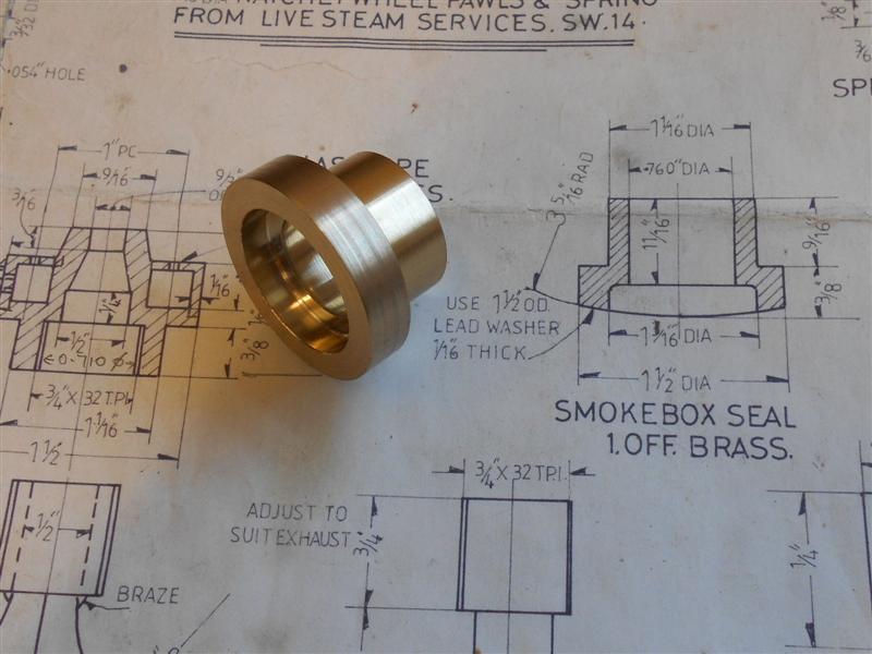 To create the radius to fit the bottom of the smokebox, I made a mandrel from a length of 7/8" diameter mild steel bar to mount the spacer on. I turned a spigot on one end about 1/4" long and included an M10 tapped hole, the M10 bolt being tightened with a box spanner and faced off before mounting in the four-jaw.  By making the bar about 6" long, there was no need to balance the chuck. The head was rested on the outer diameter of the chuck and a 3/32" spacer used at the other end to square the bar to the bedway. Because there will be a lead seal underneath the spacer, the actual turned diameter is unimportant within plus or minus a quarter-inch. The only thing of note was the need to lock the cross-slide before each ten-thou pass to stop the slide being dragged in by the cut.  This is turned at about 6.3/4" diameter and sits well in the bottom of the smokebox.  Thanks for looking in, Steve |
|
|
|
Post by mr swarf on Jul 7, 2018 21:29:48 GMT
That's a nifty way of doing it, must make of note of it.
Paul
|
|
|
|
Post by springcrocus on Jul 10, 2018 21:21:13 GMT
The blastpipe nozzle, as drawn, cannot be made as a single component. I have made it in two parts, starting with the lower body, turning the O/D and screwcutting the internal 3/4" x 32tpi mounting thread. Because the thread goes tight to the back, I kept the half-nut engaged and turned the chuck by hand. A thread this fine only needs five or six passes. All the bores were done at this stage also.  This was then reversed in the chuck and the 3/4" diameter section turned, leaving a 1/8" wide flange at the base. I also turned a small mounting spigot on the flange to locate the upper part. This upper ring was made from the same 1.1/2" diameter material and was machined to fit on the body. Although John (simplyloco) used a plumbing fitting, I was unable to find one suitable to my situation.  The two parts of the body are ready for soldering together but this is the only picture I have of the two parts before joining, the blastpipe and threaded collar have been seen before.  Finally, the component was loaded back in the lathe and the top angle produced with the compound slide set round at twenty degrees. The ring of thirty-thou blower holes were done on the mill using the six-hole solution from the Zeus book.  The position of the hole for the steam entry fitting to the blower ring will be marked once I've assembled all the components together. If I do it now, Sod's law determines that the hole will be in the worst position possible. Thanks for looking in, Steve |
|
|
|
Post by springcrocus on Jul 15, 2018 6:04:13 GMT
Although the drawing calls for 7/16" dia x 18 swg copper tube for the steam pipes, I had a short length of 12mm x 1mm wall tube in stock and have used that instead. I have also beefed up the flange to the cylinder from 1/8" thick to 3/16". I started by milling up a pair of rectangles from 3/16" brass plate, then drilled the two bolt holes 4BA clear. For the steam pipe hole I first drilled through at 10mm dia followed by a 12mm slot drill to a depth of 1/8". The tube was parted off to length and polished down to be an easy fit in the flange. 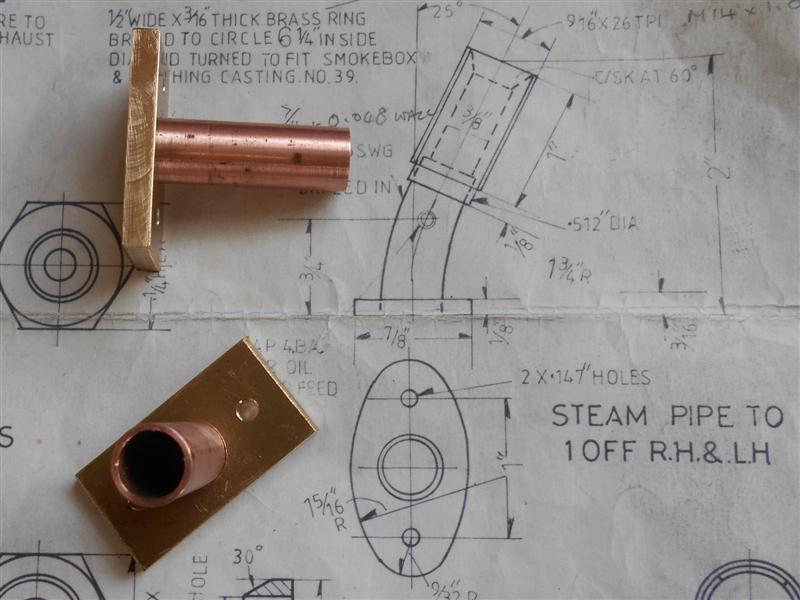 They were then silver-soldered together and, because the tube was nicely annealed from the silver-soldering, I put the bends in using a convenient spring and a M8 bolt that happened to fit nicely together.  The bending distorted one of the tubes at the mouth but I was able to get it circular again by pulling it up tight in a 12mm mill collet.  A 9/16" dia filing button was made and the shape of the flange finished freehand on the linisher using the button as a guide. Here is the first one bolted to the cylinders. 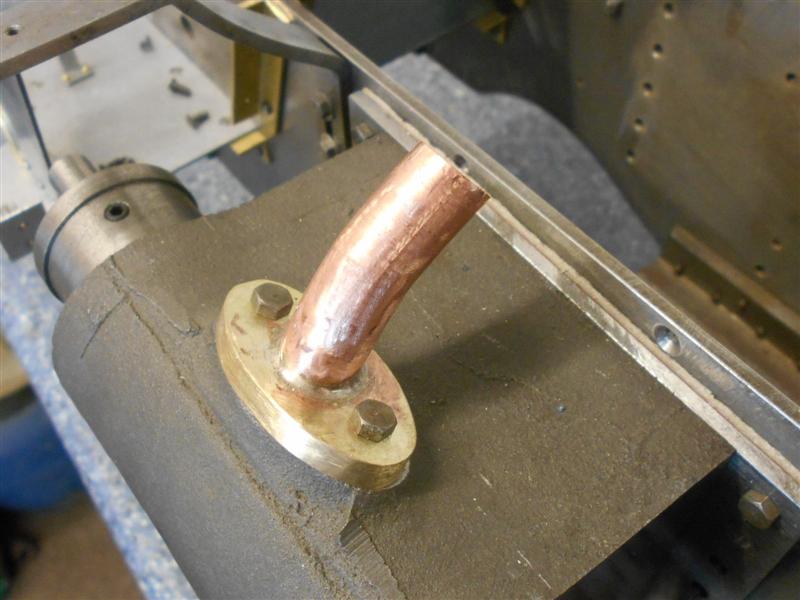 I shall silver-solder the oilfeed clack and the top threaded section on later, after the tap for the nuts arrives and I can check the sizes. Thanks for looking in, Steve |
|
|
|
Post by nomaduk on Jul 16, 2018 15:15:02 GMT
Hi Steve, Can I just say i'm enjoying reading through this thread / Diary. I have recently purchased a 5 inch gauge Part built britannia, almost complete just a few odds and sods to finish off, Im not fully experienced in model engineering so thought a part built may be the best way to start. it's an amazing thing, highly detailed so a little nervous about doing something to damage the previous owners hard work I have joined a local club whose members have offered to help as much as they can but am aware it's not a quick thing to finish, not if I want it done right I got the 5 inch almost complete just running boards and piping to complete and a 3.5 inch which has a lot to finish. my idea was to learn with the almost complete one so that when I come to start the 3.5 I will have a better working knowledge on the others. I may have to ask for advice on a few parts but will try my best to research first. I inherited my equipment from my dad who had collected everything with the focus of making a steam train, he unfortunately never got around to it. so yeah, again thanks for the amazing work and detailed pictures, looking forward to the next installments. David |
|
|
|
Post by springcrocus on Jul 16, 2018 19:05:13 GMT
Hello David, I'm pleased that you have found the build diary useful. Since your major challenge will be the 3.5" Britannia, be sure to check out simplyloco's "Brit progress" thread which contains a wealth of information. I'm sure you will derive much satisfaction in completing both of your projects and wish you good luck with them. I've used M14 x 1 rather than 9/16" x 26tpi for the top section of the steam pipes and started by making the nuts. They should be made from 19mm or 3/4" AF hexagon but, not having any, I made them from 7/8" dia round bar instead. I drilled and tapped deep enough to get five nuts from the bar and then moved over to the mill to create the hexagon. I couldn't be bothered to set up the rotary table, nor did I have any larger hex bar to make a holder, so used a thirty degree plate to set the angles instead.  After doing three sides, I used a different way to set the intermediate angle, then continued as before. This is not super-accurate but it doesn't need to be, just close enough to fit the spanner.  Then it was back to the lathe to chamfer and part off each nut. 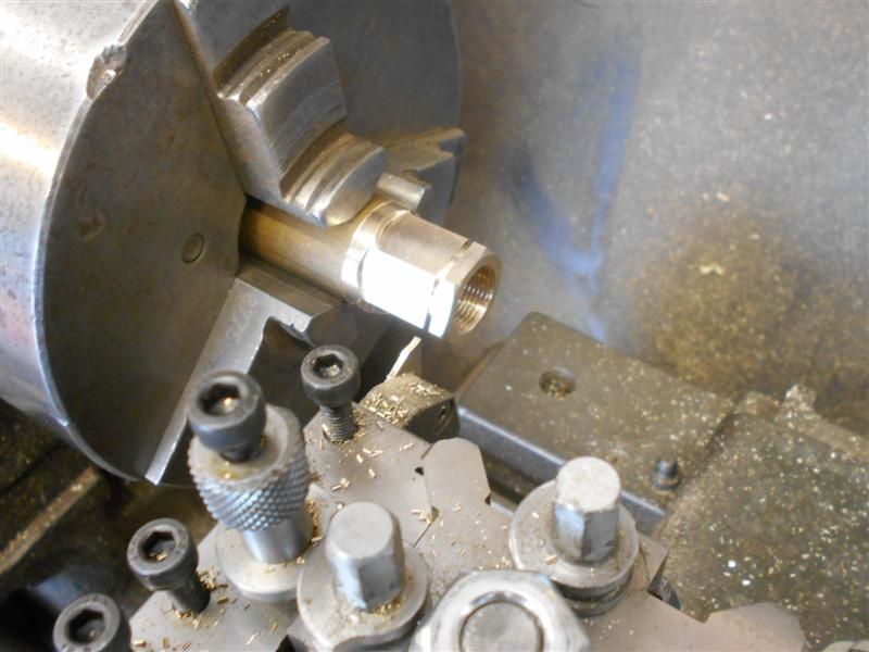 The threaded sleeves were made next, using the nuts as a gauge, and with a spigot bored in one end. This was made to be an easy fit over the steam pipe. The clack bodies were made earlier (no pictures) and the steam pipes had a hole put in the side to set the clack bodies into. The whole lot were then silver-soldered together, cleaned up and the threads run down again.  The one on the right is a little distorted near the base due to having to tweak the angle a bit, but it's never going to be seen once assembled so not worth trying to do anything about. Things will be slowing down a little now as I'm starting to pull together a load of loose ends and am getting ready to set the return cranks and make the eccentric rods. Then it will be set the timing and a shot at running on air. I haven't got a clue what I'm doing so it could be a hilarious experience or it may end in tears. Time will tell. Thanks for looking in, Steve |
|
|
|
Post by springcrocus on Jul 22, 2018 18:32:41 GMT
I've been playing around with the cylinder cladding, not really knowing what I'm doing to be honest. I've decided to try and replicate the original a little closer than drawn and worked out numbers and positions of rivets for fixing. The drawing calls for 22 swg brass or copper sheet but I'm using 28 swg (eighteen thou) because it doesn't look so bulky. First, I marked out the cutaway for the steam pipe and flange, leaving some material to make into tabs.  I've clamped the two pieces onto some 12mm MDF and am using a 1/8" cutter to remove the waste. Once that was complete, I reclamped the job and drilled the various rivet holes, 1/16" for the fixing rivets and 3/64" for the inspection cover-plate, or whatever it is.  The positions of the rivets were guessed with reference to a photo I took at Bressingham twenty years ago. The larger holes are for the cylinder cocks. One can see where I'm attempting to make the tabs to support the steampipe cover part of the cladding  To make a perfect circle in thin material is not easy and I chose to screw a pair of blanks to a block of roof batten and set it in the rotary table. I only had to find the centre of rotation - centre of the chuck - and not worry about the position of the material.  After drilling the four 1.2mm holes on a 3/4" PCD, I then loaded the 1/8" slot drill and wound out to 0.531" on the "Y", 0 on the "X" axis. After plunging through, I was then able to wind the rotary table round to create the 15/16" diameter circle needed. After getting about half-way round, I added a couple more screws and washers to hold the discs firm.  I then returned to datum, set the cutter down to depth and finished the cut.  After a bit of cleaning up, they were then riveted to the cladding with 3/64" brass rivets.  I will now muddle on with the next stage which is to get the bending done and the rivet holes transferred to the cylinders. Thanks for looking in, Steve |
|
don9f
Statesman
Les Warnett 9F, Martin Evans “Jinty”, a part built “Austin 7” and now a part built Springbok B1.
Posts: 960
|
Post by don9f on Jul 22, 2018 19:57:11 GMT
Great job, the full size probably has 16swg cladding material, so your 18 thou is a much better choice. The inspection plate would give access to the drain pipe connection under the steam chest....the pipe going down to the actual drain valve mounted under the cylinder, between the drain cocks. This would automatically open once the regulator was shut and steam chest pressure had dropped to near zero. I’m not sure on Brits, but access may also be given to the cylinder barrel upper lubrication connection. See here and note how rough it all looks
Cheers Don |
|


