|
|
Post by springcrocus on Jul 22, 2018 21:10:36 GMT
Great job, the full size probably has 16swg cladding material, so your 18 thou is a much better choice. The inspection plate would give access to the drain pipe connection under the steam chest....the pipe going down to the actual drain valve mounted under the cylinder, between the drain cocks. This would automatically open once the regulator was shut and steam chest pressure had dropped to near zero. I’m not sure on Brits, but access may also be given to the cylinder barrel upper lubrication connection. See here and note how rough it all looks
Cheers Don I always wondered what the middle drainpipe was for, now I know. Many thanks for that, Don. Kind regards, Steve |
|
|
|
Post by 92220 on Jul 23, 2018 8:06:12 GMT
Great job, the full size probably has 16swg cladding material, so your 18 thou is a much better choice. The inspection plate would give access to the drain pipe connection under the steam chest....the pipe going down to the actual drain valve mounted under the cylinder, between the drain cocks. This would automatically open once the regulator was shut and steam chest pressure had dropped to near zero. I’m not sure on Brits, but access may also be given to the cylinder barrel upper lubrication connection. See here and note how rough it all looks
Cheers Don Hi Don.
I've just had a look at the BR 9f drawings and the backhead is 12 SWG and the main cladding is 16swg, as you suggested. I'm guessing the Brit will be the same as the 9f.
Bob.
|
|
|
|
Post by 92220 on Jul 23, 2018 8:19:09 GMT
Hi Steve.
Very nice work! You were saying about the difficulty of making a perfect circle in thin sheet brass. I must remember your method. Very handy. When I wanted to machine 22 thou brass sheet to make the steps on my buffers, I sandwiched the brass blanks between a couple of 3mm BMS blanks to machine them to shape. The brass sheet came out with just a very sharp edge and no burrs anywhere. A quick lick over the edges with a fine swiss file took off the sharp edges.
Bob.
|
|
|
|
Post by springcrocus on Aug 4, 2018 15:54:19 GMT
I have made the rear cylinder caps from cast iron although the glands are from broze offcuts. I made the glands first because I wanted to fit them to the cylinder caps before final sizing. The bore is just pilot-drilled at 1/4" diameter in the photo.  To make the cylinder cap, I started by turning the O/D and forming the locating spigot for the cylinder bore, leaving it twenty thou above finish size. A 1/4" pilot hole was drilled through the billet as well. 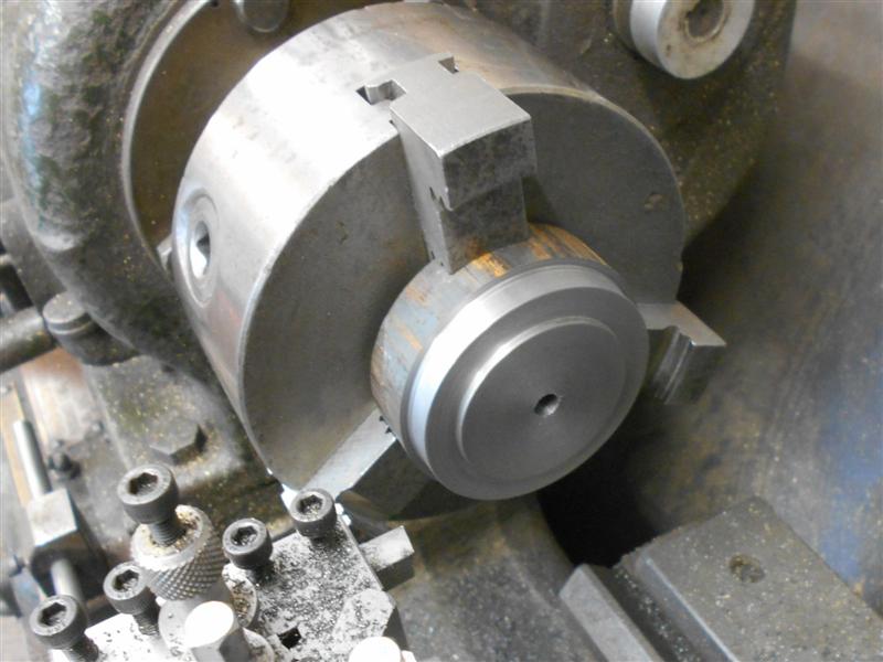 They were then loaded to soft jaws and the second operation undertaken. It seemed a shame to waste so much cast iron machining the gland housing so I removed a ring of material using a hole saw to create a radial groove in the face and then parted the ring off. These will come in useful for something one day.   The rest of the machining was then completed, ensuring that the gland was a good fit in the housing. Moving over to the mill, all the holes were drilled on their respective PCD's in a similar fashion to the front caps (covered earlier) and the gland fixing holes tapped 8BA. 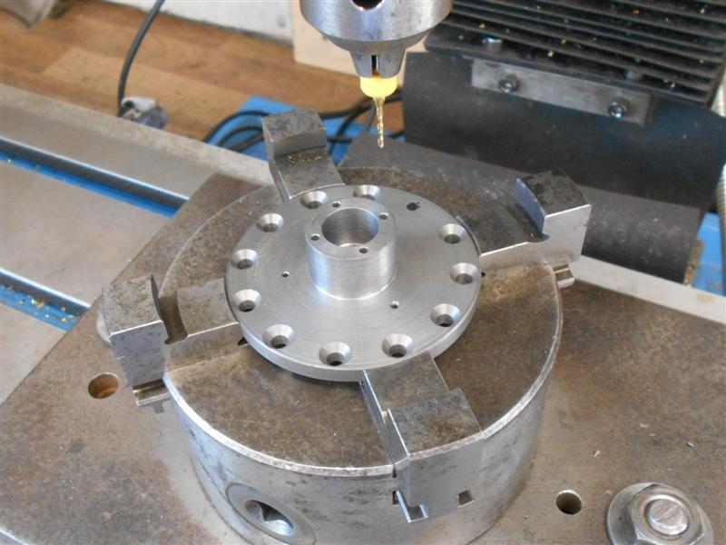 8BA studs were then fitted to the end caps and the glands inserted and nutted down tight. The assemblies were then returned to the lathe, held in soft jaws, and the piston rod holes bored and reamed to size. The cylinder locating spigot was also skimmed to final diameter, plus a couple of thou off the face, which ensures that the whole assembly is perfectly concentric with the bore of the cylinder.  Finally, the steam inlet recess was formed in the same manner as the cylinder front caps. The underside of the glands and the housings have been notched to aid correct repositioning. A piece of 3/8" dia centreless ground material has been set in place to check the fit.  Thanks for looking in, Steve |
|
|
|
Post by Roger on Aug 4, 2018 16:27:36 GMT
Hi Steve,
I'm not seeing any pictures on this thread at the moment. Am I the only one with that issue?
|
|
johnthepump
Part of the e-furniture
 Building 7 1/4"G Edward Thomas
Posts: 494 
|
Post by johnthepump on Aug 4, 2018 16:58:43 GMT
Hi Steve, I'm not seeing any pictures on this thread at the moment. Am I the only one with that issue? I can’t see any pics either. JtP. |
|
|
|
Post by GWR 101 on Aug 4, 2018 17:49:04 GMT
Hi, I have pictures and very nice they are great work Steve. Regards Paul
|
|
|
|
Post by Roger on Aug 4, 2018 18:10:03 GMT
Ah, I have them now. How odd, there were just blank spaces between the blocks of text. Nice work Steve, I would never have thought of using a hole saw for that.
|
|
|
|
Post by simplyloco on Aug 4, 2018 19:31:07 GMT
Hi Steve, I'm not seeing any pictures on this thread at the moment. Am I the only one with that issue? Me too. It's been like that for weeks, with just the odd intermittent exposure - pun intended! In fact, I only see intermittent images from anyone who uses Imgur: i get 'Privacy Issues' all the time. John |
|
|
|
Post by springcrocus on Aug 4, 2018 21:27:10 GMT
Hi Steve, I'm not seeing any pictures on this thread at the moment. Am I the only one with that issue? Me too. It's been like that for weeks, with just the odd intermittent exposure - pun intended! In fact, I only see intermittent images from anyone who uses Imgur: i get 'Privacy Issues' all the time.John Luckily for me, I don't normally get problems as I pay to have mine hosted. Everyone gets server issues from time to time, but free hosting is always going to be more problematic than a paid-for service like I subscribe to. One picture got left behind in the last update, evidence that I've followed Julian's advice and made the ports more free-flowing.  The front caps have been modified in a similar manner. Regards, Steve |
|
|
|
Post by springcrocus on Aug 10, 2018 16:16:23 GMT
I've read the various descriptions on the forum for finding the dead centres of the motion, and various members have offered advice (for which I'm extremely grateful) but I found the article by an American gentleman, Jeffrey G. Hook of the Deerfield and Roundabout Railway, to be the easiest to understand and I have followed his procedure on Britannia. If anyone wishes to read his original article it may be found at the bottom of the page HERE and the PDF document found HERE. Packing pieces are set on top of the axle boxes to simulate the correct ride-height in normal operation. I started by making a wheel tram from a piece of tough 3mm dia steel (marine engineers may be familiar with needle-gun needles for de-scaling etc.) and choosing reference points on the loco to locate the tram. I chose to use the expansion link brackets and set a small dimple in each one accordingly.  I worked on the driver's side first, rolling the loco along the bench until the crosshead was at the far right in the slidebar brackets and blued up the top quarter of the driving wheel. Then I rolled the loco forward about an eighth of a turn of the wheel and zeroed the DTI on the front of the crosshead.  Using the wheel tram a line was scribed across the rim of the wheel.  The loco was then rolled backwards until the crosshead "turned the corner" and came back to the same reading on the DTI. At this point, a second line was scribed on the wheel rim. I then repeated the operation for both lines to check that nothing had moved whilst rolling the loco back and forth. Using a digital caliper, I scribed a horizontal line across both perpendicular lines and set a tiny dimple at the two intersections. Using a pair of dividers, I scribed two more arcs to nearly meet in the middle and marked the horizontal to these arcs also.  An indent was made between the arcs on the horizontal line and when the wheel tram is placed in the indent and rested in the reference point, the wheel is exactly on back dead centre.  To find the front dead centre, the procedure was followed again but with the crosshead at the front of the slidebars and the clock measuring from behind the crosshead. 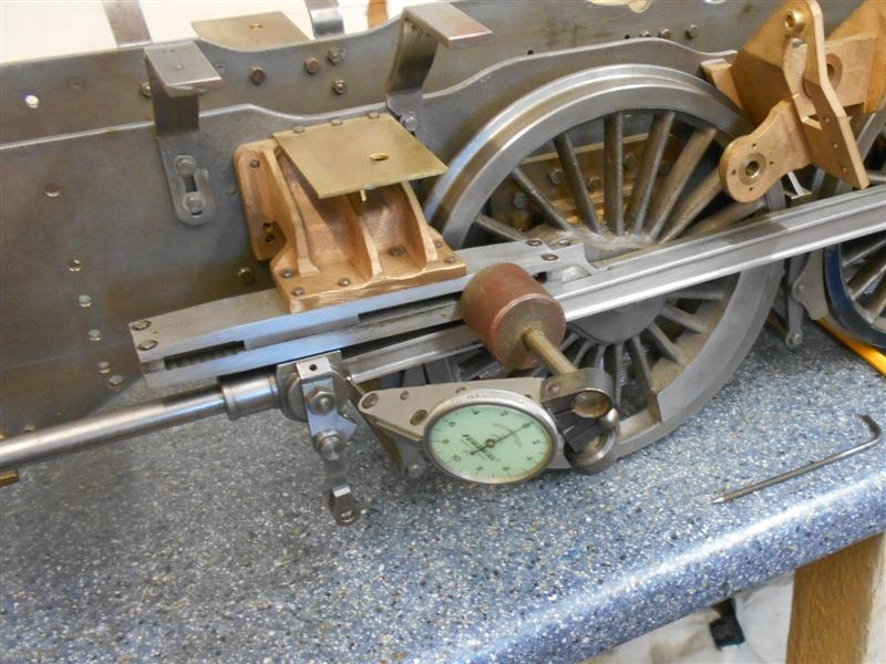 The loco was then turned round and the exercise repeated for the other side. Now that I can accurately find the dead centres I can move on with setting the return cranks to their correct positions. After that, the wheel tram will be put in a safe place to ensure it can't be found if it's ever needed again. Thanks for loooking in, Steve |
|
stevep
Elder Statesman

Posts: 1,070
|
Post by stevep on Aug 10, 2018 16:35:23 GMT
Steve,
That is very interesting. I did something similar for my engines, but simply clamped a toolmakers clamp on the slidebar, and turned the wheels until the crosshead came up against the clamp. Somewhat easier than setting up the DTI, and, I would suggest, just as accurate.
I think the use of the "wheel tram" is excellent. I made my reference centre punch on the frame, and used dividers to mark the wheel rim, but the use of the wheel tram (if it is kept as part of the engine toolkit) means that the dead centres can be re-established again whenever necessary.
Thanks for sharing...Steve
|
|
|
|
Post by jagmanal on Aug 10, 2018 20:02:35 GMT
Hi Steve,
The process you described for finding back and front dead centre is exactly how it is done on the big stuff except doing it with 70 tons of loco is a bit harder work! The other process that is done is to bump the piston against the front and back cover and each time mark where the crosshead comes to on the slidebars, when the whole lot is coupled up to the wheels you will be able to check the piston clearance on the covers. The dimension of the clearance on the cover is not crucial but if it is a very near miss on the front cover it could strike it when the piston rod gets hot and gets a bit longer. Examination of the slidebars on the real stuff you will more than likely find the scribe lines with 4 centre pops along it to ensure it can be seen at a later date. Cheers Alan W
|
|
don9f
Statesman
Les Warnett 9F, Martin Evans “Jinty”, a part built “Austin 7” and now a part built Springbok B1.
Posts: 960
|
Post by don9f on Aug 10, 2018 20:35:16 GMT
Steve (springcrocus), I especially liked the final sentence in your description above! 😂
Cheers Don
|
|
barlowworks
Statesman
Now finished my other projects, Britannia here I come
Posts: 874
|
Post by barlowworks on Aug 10, 2018 22:21:23 GMT
Steve, if you paint it with bright yellow fluorescent paint you will be even more annoyed when you can't find it next time. 🤔
Mike
|
|
|
|
Post by springcrocus on Aug 10, 2018 22:30:15 GMT
Hi Steve, The process you described for finding back and front dead centre is exactly how it is done on the big stuff except doing it with 70 tons of loco is a bit harder work! The other process that is done is to bump the piston against the front and back cover and each time mark where the crosshead comes to on the slidebars, when the whole lot is coupled up to the wheels you will be able to check the piston clearance on the covers. The dimension of the clearance on the cover is not crucial but if it is a very near miss on the front cover it could strike it when the piston rod gets hot and gets a bit longer. Examination of the slidebars on the real stuff you will more than likely find the scribe lines with 4 centre pops along it to ensure it can be seen at a later date. Cheers Alan W Damn good tip, thanks for that. Regards, Steve |
|
jma1009
Elder Statesman
Posts: 5,901
|
Post by jma1009 on Aug 10, 2018 22:59:10 GMT
Hi Steve,
I am pretty sure that your method for establishing FDC and BDC is pretty good and accurate, though it is not necessary to 'clock' the crosshead. I have always used the Don Ashton proceedure, which eliminates error caused by any play in the crosshead small end and conn rod big end. In a new loco such as yours to your high standards these errors will be minimal if not at at all.
Nice to see someone doing things nearly correctly to establish the correct FDC and BDC, rather than guess when the piston is at the end of it's stroke, when the piston is moving very slowly if at all, but the valve is moving very quickly at this point in it's cycle; so accuaracy and eliminating errors is of primary importance for subsequent good valve events.
Cheers,
Julian
|
|
|
|
Post by springcrocus on Aug 11, 2018 6:59:17 GMT
Hi Steve, Nice to see someone doing things nearly correctly to establish the correct FDC and BDC, rather than guess when the piston is at the end of it's stroke. Cheers, Julian  Love it! That's a left-handed compliment, if I've ever heard one.  Regards, Steve |
|
|
|
Post by gwr14xx on Aug 11, 2018 7:37:23 GMT
There's nothing wrong with left handed! All clever people are left handed - and so am I!
Eddie.
|
|
|
|
Post by jagmanal on Aug 11, 2018 19:42:24 GMT
Now you have your FDC and BDC marked you can also use that to set your valves (this is before you lose your trammel in your safe place!). If you carefully measure where your port edges are in respect to the cover face (4 dimensions) and your ring edges in respect to the front of the valve spool (another 4 dimensions) you can then measure down from the front cover face to the front of the valve spool when at FDC/BDC and then calculate exactly where the valve rings are in relationship to the ports and in theory should have a small opening for lead steam. Repeat this for each FDC/BDC in forward and reverse and you should end up knowing the lead in all cases and should be equal but you might find the dimensions slightly different in reverse, I was advised to do this in a short cut off, 10%, as any inaccuracies are less apparent in full gear. My only worry about this process is how you achieve the accurate port edge measurements. Having said all this there is probably a seasoned modeler out there who will say stuff all that palaver and tell us a quick and easy way to set valves! Cheers Alan W
|
|


 Love it! That's a left-handed compliment, if I've ever heard one.

