jma1009
Elder Statesman

Posts: 5,901
|
Post by jma1009 on May 30, 2019 20:43:13 GMT
Hi Steve,
I would certainly be interested to see your boiler build, but there is something 'stagnant' about a photographic record of something already done, as opposed to a current 'timeline' of the moment.
A 'current timeline' is always going to be more interesting and exciting as opposed to "I did this 6 months ago and here it is finished..."
And a forum is just that - an arena for debate and discussion. If you don't like debate and discussion then - well - there are not many alternatives if perhaps all you want is sycophantic praise and an ego trip.
If things go a bit off topic such as your quoted p.30 then just accept it, and be happy that some very knowledgeable expert model engineers have contributed.
Sometimes I think you are being a bit too 'precious', and do not understand that a forum is - well - a "forum".
There is nothing particularly special about your build thread so far. We all bit our tongues and restrained our typing fingers when you rebuffed Don Ashton early on over your key quartering positioning, and later not wanting to do a proper reverser thread for the screw reverser, or seeing coupled wheels with cast springs as opposed to proper leaf springs.
When people have commented, you have become 'snappy', and intolerant of any slight criticism.
You are actually fortunate - when I started this lark the IWMES courtesy of Arthur Grimmett employed the very harsh and drastic "window test".
Cheers,
Julian
|
|
|
|
Post by Cro on May 30, 2019 21:41:53 GMT
Hi Steve, I would certainly be interested to see your boiler build, but there is something 'stagnant' about a photographic record of something already done, as opposed to a current 'timeline' of the moment. A 'current timeline' is always going to be more interesting and exciting as opposed to "I did this 6 months ago and here it is finished..." And a forum is just that - an arena for debate and discussion. If you don't like debate and discussion then - well - there are not many alternatives if perhaps all you want is sycophantic praise and an ego trip. If things go a bit off topic such as your quoted p.30 then just accept it, and be happy that some very knowledgeable expert model engineers have contributed. Sometimes I think you are being a bit too 'precious', and do not understand that a forum is - well - a "forum". There is nothing particularly special about your build thread so far. We all bit our tongues and restrained our typing fingers when you rebuffed Don Ashton early on over your key quartering positioning, and later not wanting to do a proper reverser thread for the screw reverser, or seeing coupled wheels with cast springs as opposed to proper leaf springs. When people have commented, you have become 'snappy', and intolerant of any slight criticism. You are actually fortunate - when I started this lark the IWMES courtesy of Arthur Grimmett employed the very harsh and drastic "window test". Cheers, Julian Hi Julian, I think this could have been another moment where you could have restrained your 'typing fingers'. As Steve has said he had a puprose in mind for this thread and wasn't trying his best to stick to that format with a small amount of contribution where applicable and otherwise support for his build and he has repetitively asked for that as others do in their own threads so I don't think it is for us to tell him he is wrong or to live with it. As it has taken us until now to convince Steve that posting on here again is worth while and enjoyable for us and himself this post of yours complete supports his reasons for not and will probably now turn him 180degrees back in the opposite direction. Let's just respect each other's wishes in their own logs such as this one and enjoy the content rather than critiscising the work. We may not all agree with how you do things (or anyone else) but it doesn't mean it's wrong or our way is right so let's be a bit more respectful of people's build choices and methods. Look forward to the updates recommencing soon Steve. Adam |
|
|
|
Post by springcrocus on May 30, 2019 22:34:13 GMT
Hi Steve, ...there are not many alternatives if perhaps all you want is sycophantic praise and an ego trip. If things go a bit off topic such as your quoted p.30 then just accept it, and be happy that some very knowledgeable expert model engineers have contributed. Sometimes I think you are being a bit too 'precious', and do not understand that a forum is - well - a "forum". There is nothing particularly special about your build thread so far. We all bit our tongues and restrained our typing fingers when you rebuffed Don Ashton early on over your key quartering positioning, and later not wanting to do a proper reverser thread for the screw reverser, or seeing coupled wheels with cast springs as opposed to proper leaf springs. When people have commented, you have become 'snappy', and intolerant of any slight criticism. ... Cheers, Julian Do you really believe that, Julian? That I dare to walk outside the shadow of the gods? That I can't offer an alternative way of reaching a satisfactory result? I'm not going to argue with you, I quietly faded into the background eight months ago rather that cause a fuss. I've never claimed to be anything more than a reasonably competent machinist and all I try to pass on is my machinist's knowledge. However, I do have more than just a basic grasp of engineering principles, even if you don't agree with some of my statements. If I'm ever lucky enough to complete this locomotive, and if you want to come back to the island, you can be the first to drive it. In fact, I would be honoured if you would because I've got no real interest in driving at this time. In the meantime, I'm still building - both Britannia and an Allchin traction engine. And you? Any chance of an update? Regards, Steve |
|
|
|
Post by springcrocus on May 31, 2019 8:17:11 GMT
Roger, I understand your reasoning but, for me, the story of the journey is what it's all about. I have absolutely no interest in creating a photographic record with little or no supporting documentary. For people who just want to look at pictures u-tube videos may be the way to go. Wilf, as you may well become an integral part of this boiler build you will probably be heartily sick of the damn thing by the time it's finished. I shall probably need Pumphouse support for a boiler this size since I have absolutely no experience of boilermaking. Mike, don't look in my tender. Inspired by you recent work, I've blatantly copied the filter and valve arrangements you described for providing the boiler with clean water, in addition to Adam's wonderful, working filter boxes. Nowt so strange as folk!  During my five years on the forum, I have tried to share knowledge with many threads in the "Tools" section and tried to promote dialogue by introducing topics for discussion when the forum was moribund (what a lovely word, John  ). I have also tried to contribute positively to threads initiated by others and most of these appear to have been well-received and of interest to others. Yet when I ask that people respect just one thread, my personal record of my loco build, and keep comments and interuptions to a minimum, it's insinuated that I'm a prima donna, an egotist, a glory-hunter. A while back, before George and Jason undertook roles as supervisors, arguments abounded on this forum and there were, at times, more threads about personalities than there were about model engineering. I've never been one to sit on the sidelines and see an injustice done and, consequently, upset a lot of people with some forthright comments about members' behaviour. Nobody, however, likes a self-appointed policeman and I'm sure that I'm still on many peoples' s**tlist because of this. To those people I've offended I give a genuine apology but the forum appeared a bit wild-west at times and needed to have a slow-down before it became a melt-down. Now that I decide to continue the record of my build, it's still controversial and divisive. Sigh! Funny old world, and as I said at the start of the paragraph "Nowt so strange as folks".  Regards, Steve |
|
Midland
Elder Statesman
Posts: 1,870
|
Post by Midland on May 31, 2019 8:50:23 GMT
Steve
I for one love to watch how you magically change a lump of metal into something real and useful, your smoke box door etc for example. If you get sniffy comments, ignore them, just we did a showoffy kid!
Keep up the inspiration!!
D
|
|
|
|
Post by racinjason on May 31, 2019 13:02:34 GMT
Gent's
Can we leave this alone now and respect Steve's wish to leave this thread for his build diary.
Cheers Jason.
|
|
|
|
Post by ettingtonliam on May 31, 2019 15:15:54 GMT
Suits me. As I'm not building a Brittania and never likely to, I needn't waste my time reading it.
|
|
|
|
Post by springcrocus on May 31, 2019 17:18:46 GMT
I have made the valve front covers from cast iron, in this case from some old but better-quality sash weights. I machined the O/D and the spigot for the valve sleeve first, and drilled the valve rod guide hole to depth at the same visit. The parts were then reversed in the chuck and the rest of the machining completed as a single operation. They are held in place with a pair of M6 cap screws topside and underside.    Steve |
|
|
|
Post by springcrocus on May 31, 2019 17:25:04 GMT
I have made the pistons from cast iron billets, whilst the piston rods are made from an unknown grade of stainless steel and I am using two cast iron piston rings rather than the single "O" ring specified on the drawing. I started by cleaning up one face and the O/D of the billets, then prepared some soft jaws for subsequent operations. The O/D was left thirty thou up for finishing after assembly but the bore and thread were finished to size at this visit.  My billets were just over an inch long and I was able to get a piston ring from each one but I missed a trick by not ordering slightly longer billets to enable two or more rings to be made from the surplus. These were made first, then the piston body was faced to length.  This was followed with the piston rods, machining to finished length and forming the thread. Because I only have one 5/16" x 40tpi button die in carbon steel, I didn't want to risk it with stainless steel so looked for an alternative. I have got a M8 x 1.0 die, though, and it was cheaper to use this and buy a matching tap for the piston body.  The rods were screwed into the bodies and pulled up really tight. The assembly was returned to the lathe and set up between centres prior to finishing the outside diameter to 1.749", and the two ring grooves formed. I have made these 1/8" wide by just over 1/16" deep since this seems to be a standard size.  Returning to the rings, the soft jaws were remachined to the new diamater and the billets reversed in the chuck. The front ends were skimmed to true the face, the inside bored out to 1.625" and the O/D finished at 1.750". The rings were parted off at 0.125" wide.  Two more rings were made from raw stock and all four were then carefully broken at a single point by holding in the vice and being given a sharp tap from a hammer and punch. The inner faces were filed smooth and square to help the next part of the job.  Next they had to be expanded for an easy fit over the piston and to give a spring contact to the bore of the cylinder. They were sprung onto a length of 3/16" thick flat stock and heated until cherry red, at which point they dropped off the flat stock and were left to cool.  After a light clean-up with some wire wool, they are ready for assembly onto the pistons.  Steve |
|
|
|
Post by springcrocus on May 31, 2019 17:26:32 GMT
Because I had to enlarge the hole through the valve guide, I have made my valve spindles from 6mm dia stainless steel with a M5 thread at the slidebar end and using M6 x 0.75 for the bobbin locking screws rather than the specified 7/32" x 40 tpi. The drawing incorrectly suggests using 2BA nuts on these threads. The central area has been reduced to 5mm to ensure it clears the root of the thread.  I also drilled a 5/16" dia hole through my button-die holder mandrel to allow the spindle to pass further through the die-holder. The nuts were made from some 3/8" hexagon brass and used as a gauge to set the size of the male thread.  I haven't decided how I'm going to make the bobbin at the moment but have some 25mm dia cast iron on order to make the bodies. Thanks for looking in, Steve |
|
|
|
Post by simplyloco on May 31, 2019 17:41:01 GMT
Suits me. As I'm not building a Brittania and never likely to, I needn't waste my time reading it. Are you sure about that? After all, most of us would probably learn something from it, including how to spell Britannia properly...  |
|
|
|
Post by ettingtonliam on May 31, 2019 19:09:51 GMT
OK, my keyboard skills are poor due to ulna nerve damage which leaves my fingers numb, and I apologise for not using Spellcheck.
The chances of me needing to spell 'Britannia' again are fairly slim.
|
|
Midland
Elder Statesman
Posts: 1,870
|
Post by Midland on May 31, 2019 21:09:17 GMT
Steve
For the first time I can say that is the way I do it! Either you are now as smart as I am or I am thrilled to see that maybe I got it right. No matter. I am not doing a Brit but my god do we learn from you guys! Now spell accommplisshement backwards to get your gold star!
D
|
|
|
|
Post by Cro on May 31, 2019 21:32:57 GMT
Can I offer a useful tip on the valve spindles Steve as I imagine it might not be too late. After taking the B1 spindles out the other day I found that there was no satisfactory way to grip them to unscrew them from cross head, if a hex had been machined onto the end of the spindle I could have used a nut runner to undo it quite easily. Just thought it was a useful tip which I'll be doing to the 9f one day.
Adam
|
|
|
|
Post by springcrocus on May 31, 2019 22:07:10 GMT
Sorry, I got a couple of posts out of sequence. The eccentric rods should have followed this and the next couple of posts. Following on from the procedure of finding front and back dead centres, the next process was to find he correct position for the return cranks. Once again I followed the information provided by Jeffrey G. Hook and started with the driver's side by setting the loco in neutral, the position where the die block at the end of the radius rod is exactly in the middle of the expansion link. Rocking the expansion link back and forth creates no movement of the radius rod in this position.  A while back I made an adjustable, sliding gauge for marking out the coupling rod centres and this was used to set an approximate length of the eccentric rod as shown on the drawing. The gauge has a pair of bushes with 1/8" diameter holes, and two pins were made to fit into the return crank and the tail of the expansion link respectively, with 1/8" diameter spigots to fit the gauge.  The expansion link moves back and forth from vertical at the front dead centre position to fully tilted in one direction at middle dead centre, then onwards to vertical at rear dead centre and finally to fully tilted in the opposite direction at the other middle dead centre position. By setting a DTI on the expansion link, it is possible to measure the positions of both front and back dead centres quite accurately. When the two readings are the same, the return crank is exactly 90 degress to the centreline of the motion. Using the trammel from earlier, the loco was positioned at front dead centre and the clock set up as low down as I could. The loco was then wheeled backwards to the back dead centre position, keeping an eye on the clock. In my case, it came nowhere near contact with the stylus so the return crank clamp was loosened and the crank rotated until it just touched the stylus. The clock was moved until a zero reading was obtained and the loco was then wheeled forwards until I reached the front dead centre position again and a note made of the clock reading, which had slightly over-ran the FSD of the clock.  This back and forth process was repeated a number of times, adjusting the crank and the clock until I attained the same reading on the clock at both dead centre positions, probably about nine or ten cycles in all. When I got to the point where I was getting less than one thou difference on the clock for both front and back dead centres I called it a day and locked the return crank clamp up tight. I also took the opportunity to pin the lifting arms to the weighshaft with 3/32" taper pins, pinning the driver's side first. The link was set exactly in mid-gear and the lifting arm on the fireman's side adjusted until this link was mid-gear also. After marking the position, the firman's side was also drilled, reamed and pinned.  The crank on the fireman's side was then set, leaving only the eccentric rods to be made to finish the motion. Thanks for looking in, Steve |
|
|
|
Post by springcrocus on Jun 1, 2019 6:31:42 GMT
Suits me. As I'm not building a Brittania and never likely to, I needn't waste my time reading it. Are you sure about that? After all, most of us would probably learn something from it, including how to spell Britannia properly... I don't know how or when I upset Richard but I'm sorry that it happened. Steve |
|
|
|
Post by runner42 on Jun 1, 2019 6:39:15 GMT
Hi Steve,
your recent posts you appear to be working at a frantic pace doing so much in such a short time, then I remembered you had Britannia running on air in August 2018, so this is filling in the gap before reaching that important milestone. Congratulations on achieving this, not that it was unexpected because your workmanship is outstanding, but never the less it is something to be proud of, whether it's the first time or after many builds. I am most interested in your setups when machining either in the lathe or on the milling machine because that is the essence of achieving a high class item, after all the machine cuts the metal but you are doing the driving.
I have added your post to my favourites list and where appropriate review the applicable stage of build before attempting a similar one for my locomotive.
Brian
|
|
|
|
Post by springcrocus on Jun 2, 2019 6:21:14 GMT
Brian, you asked about this three years ago. Sorry, slow worker. Whilst setting up the second eccentric rod I bottomed the gauge on the link and managed to move the return crank which meant I had to reset the position. Upon closer inspection it turned out that the driving crank pin was not as tight a fit in the wheel hub as I thought. From all that I've read, this appears to be one of the most important parts of the motion and I didn't fancy it moving again in service. I decided, therefore, to disassemble the driving axle and fix the two crank pins to ensure they stay exactly where they are but can be removed for replacement if ever neccessary. To this end, I have drilled and tapped an M3 hole at the interface, counterboring to take a cap-screw head purely because I have loads of them. I would have just used a grub screw otherwise.  Because I could see no way of accurately pre-determining the position of the return crank, I knew there would be a problem pinning them after final adjustment. I didn't want to use a hand-drill to drill through and I couldn't see how the assembly could be dismantled without losing the position. I decided to pre-drill part way through the return crank and, after setting, take the whole axle to the mill to complete. I started by setting up a piece of 3/8" dia material in the milling vice and using this as a reverse drill jig to drill a 3/32" dia hole through the first side only of the return crank.  The cranks were then set as described previously and locked up tight with the clamp screws. All three axles were then released from the frames and the coupling rods separated from the front and rear wheels. The centre axle, complete with the front coupler and the con rod, was then taken to the mill and set up on parallel risers to enable rotation of the wheelset.  A 3/32" dia drill was used to get the pre-drilled hole in the crank vertical and the assembly clamped to prevent movement. The drill was then passed right through, followed by a 3/32" taper-pin drill and finished with the matching reamer.   Finally, taper pins were trimmed to size and fitted to both cranks. The axle was then returned to the frames and the wheeltrain reassembled. There may be an easier way to get the return cranks accurately set prior to assembly but when I asked the question on the forum, no-one could come up with an answer. Plenty of advice about WHAT to do but none about HOW to do it and retain the required accuracy. Anyway, this works for me. Thanks for looking in, |
|
|
|
Post by runner42 on Jun 2, 2019 8:17:45 GMT
Hi Steve,
thanks for that it is a prime example of innovative setups. Planning the setups is either an innate ability or you spend long hours thinking of ways to undertake an operation. If it is the latter I hope you are not distracted when your wife is talking to you, that is something that I am guilty of.
Brian
|
|
|
|
Post by springcrocus on Jun 2, 2019 21:17:15 GMT
George has tried to move this post for me but the software doesn't seem to allow it. The timeline will come correct in the next day or so. In the meantime, I've recreated it here in it's correct position. The eccentric rod needs to be made to suit the rest of the motion and differs by a small amount on each side of the loco due to machining tolerances. The distance between the bushes in the eccentric rod are correctly spaced when the loco is placed on either dead-centre and there is no movement of the valve when the radius rod is raised and lowered in the link. The distance gauge was set up as before, the locking screws released and the link pin removed from the bell crank to allow the radius rod to be raised and lowered freely. The gauge was adjusted until the condition above was obtained and the gauge locked up. This distance between the bushes was accurately measured on the mill with the DRO and this reading used to make the first eccentric rod.  The procedure was repeated for the other side, with a different reading obtained for the bush spacings. I've made the eccentric rods from some 1" x 1/2" black bar but because of the offset some method had to be devised to get them from the chosen material. Some quick maths indicated an angle of just over two degrees so, after cleaning up the outside edges, the billet was loaded to the vice resting on a two-degree angle block. The overall length was then machined using a 12mm endmill and the top of the forked end milled to clean up about 3/4" long. The quill DRO was set to zero and the other end machined with the same tool for a length of about 1" and down to 0.375" on the readout. 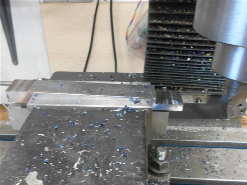 I had previously obtained an accurate measurement for the spacing of the bushes with a sliding gauge and the distance noted. I drilled and bored the hole for the bearing first and set this as the zero datum. The three bearing cover holes were drilled next using the three-hole solution, and finally the hole in the fork end was drilled and reamed 3/16" for the pivot pin at the recorded position. 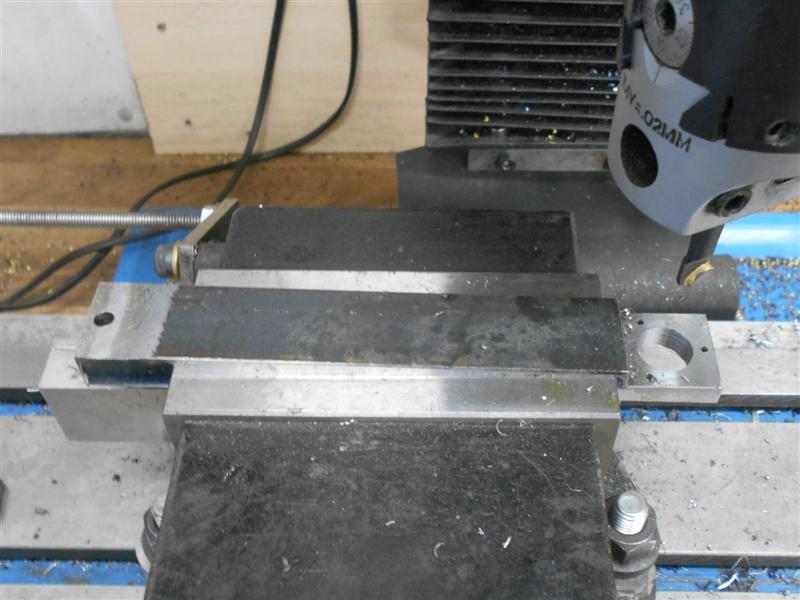 The fork was machined next using a 1/8" slitting saw, starting on the centreline , then up and down a sixteenth. 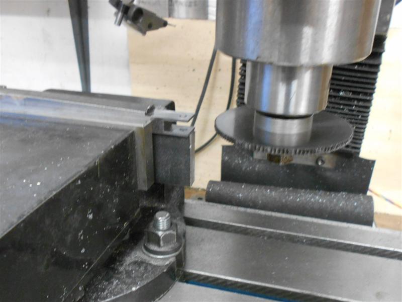 The billet was then turned over with the bearing end rested on a 3/8" thick spacer and an anti-vibration wedge placed in the fork. The two ends were then milled down to finished thickness. 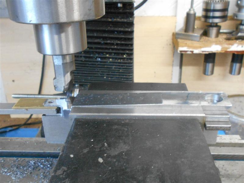 While the milling vice was still on the table, most of the rest of the surplus material was removed using carbide tooling before moving on to the final shaping operations using fixtures to hold the work. 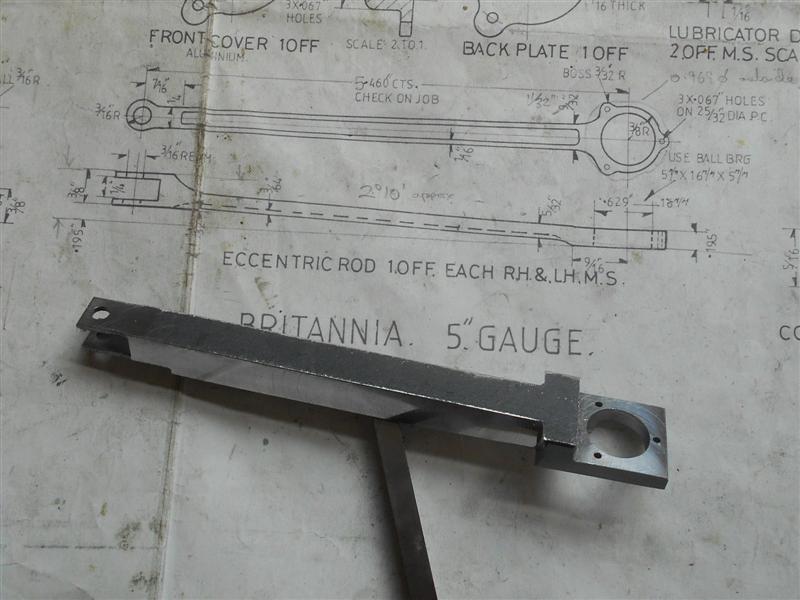 I made a mandrel to fit the bearing bore on the lathe and then transferred it to the rotary table on the mill. The three 10BA holes were put in and the work bolted onto it to allow maching of the exterior form of the bearing housing. This was done freehand with a 1/4" dia slot drill, getting the diameter around the bosses first and the thinned sections after. 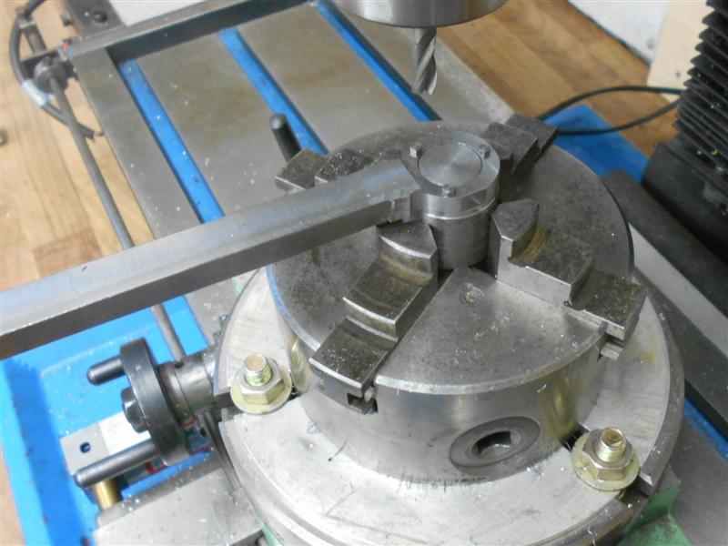 I re-used a general-purpose fixture for the final operations, using a spacer to fit between the forks for the first end and a spacer under the workpiece at the bearing end. By adjusting the position of the fixture I was able to mill the sides of the rod to produce the taper required. 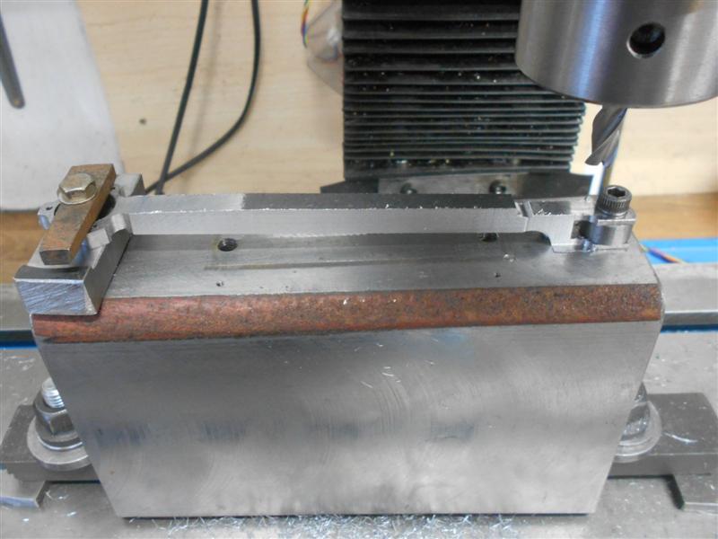 Leaving the workpiece clamped, I turned the fixture over and adjusted it to enable machining of the front using a 1/4" diameter end mill. I then followed this with a form tool to machine the flute in the front of the rod. Finally, I used a long-series 3/16" end mill to machine the back of the rod but if I'd been a bit smarter I would have used larger spacers under the rod to get a bigger end mill behind there. The rest was just the normal hand-finishing to smarten it up a bit. Thanks for looking in, Steve |
|


 ). I have also tried to contribute positively to threads initiated by others and most of these appear to have been well-received and of interest to others. Yet when I ask that people respect just one thread, my personal record of my loco build, and keep comments and interuptions to a minimum, it's insinuated that I'm a prima donna, an egotist, a glory-hunter.


