|
|
Post by Oily Rag on Apr 7, 2018 20:41:22 GMT
" Thatsa Proper Job "
|
|
|
|
Post by joanlluch on Apr 8, 2018 14:18:21 GMT
Hi Joan, Just wonderful and highly satisfying for you to have designed, built and now tested your pump. It seems to run very smoothly! Chris. Indeed Chris, one of the most satisfying things to me is watching something that I have been worked on or designed with mere conceptual tools such as 3D CAD (or just a spreadsheet, to say), to become an actual working system or device. In my case, it's not necessarily a matter of making it all myself, but to get something that actually works as previously intended. |
|
|
|
Post by joanlluch on Apr 8, 2018 17:31:15 GMT
I was not happy with the apparent high air consumption of the pump, notoriously escaping from the exhaust. This could only be the steam valves not sitting well on the ports surface. I had already carefully flattened the steam ports surface on the cylinder block, so I was sure this wasn't an issue. It could only be the sliding valves themselves, so I decided to perform yet another 0.1 mm cut on them to try and improve them. I suspected that the valves could not be totally flat because the plastic they are made of could have deformed under the pressure of the vice when machined and thus the operation resulted in a non completely flat surface after machining ended. So I held the valves again on the vice, just enough to prevent any deformation, and performed said additional 0.1 mm cut. To check the flatness I performed the cut this time with the part held at 90 degrees of the previous cuts, and started with depth increments of just 0.02 mm. This confirmed my suspicion. The mill only touched the most external areas of the part on the first few cuts. This meant the part was not indeed totally flat. So I went ahead to the planned 0.1 mm cut, now more confident that it was totally flat, and assembled it all together on the pump. (The pump has now been assembled with the inlet an outlet ports swapped for convenience reasons on the locomotive final assembly, but that's unimportant for the present discussion) This is the result VIDEO: 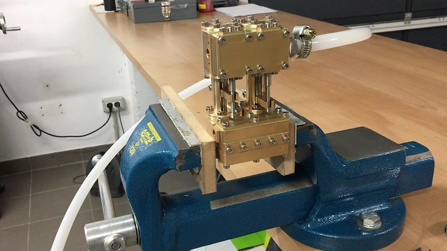 Bomba vapor Bomba vapor by joan lluch, on Flickr What a difference !. The pump now runs with just very little amount of compressed air and there's no audible air being wasted through the exhaust. Now I'm totally pleased. I have read somewhere that the flatness of both the port surfaces and the slide valves is crucial for the performance of a steam engine. Well, this has a lot of sense, of course this is how it is supposed to work, but having little experience and being my first ever attempt at making a (plastic) slide valve, I didn't think that just 0.05 mm or so out of flatness, would have made such a huge difference. So lesson learned and happy for having been able to fix the issue. Now, the next step was testing the water side of the pump. The following VIDEO shows my test arrangement and this time everything worked as I expected, at least at atmospheric pressure:  Bomba vapor Bomba vapor by joan lluch, on Flickr Very satisfied as well of the result. Joan |
|
|
|
Post by chris vine on Apr 8, 2018 18:30:45 GMT
Magic.
don't wear it out playing with it before you fit it to the locomotive!!
Chris.
|
|
|
|
Post by joanlluch on Apr 8, 2018 18:45:16 GMT
Magic. don't wear it out playing with it before you fit it to the locomotive!! Chris. Hi Chris, Wise advice!. In reality I have recorded the pump in video almost every time that I have run it, so it has only run less than 10 minutes in total since I first assembled it. I have disassembled the upper part twice to repair/fix the sliding valves and to swap the position of the inlet and outlet pipes though. I'm leaving it now alone and move onto other matters before I have to regret it. Joan. |
|
|
|
Post by runner42 on Apr 9, 2018 5:51:48 GMT
Hi Joan,
an excellent design and construction, you are a master of innovation. Have you tested the output for pressure? There seems to be plenty of water being outputted so its duty cycle should be fairly low, how is the pump switched on and off?
Brian
|
|
|
|
Post by joanlluch on Apr 9, 2018 8:12:58 GMT
Hi Joan, an excellent design and construction, you are a master of innovation. Have you tested the output for pressure? There seems to be plenty of water being outputted so its duty cycle should be fairly low, how is the pump switched on and off? Brian Hi Brian, Thanks for that. I will test the pump pressure when I have some proper arrangement to do so. I can even delay the test until the boiler is made and use the boiler for that purpose. As long as it is able to feed water into the boiler at the nominal pressure that would be enough. Or I can even try to perform the boiler pressure test with this pump, if I find it's capable enough to do so. Pumps acting like that are referred as "positive displacement pumps" in the industry. There are many types of them, such as gear, lobe, peristaltic, screw, and piston pumps among some few others. They all have in common that they draw (or suck) fluid into a compartment to later push (or move) it to the outlet for discharge. On the contrary, centrifugal pumps use centrifugal force through an impeller to create a vacuum at the inlet and pressure to the outlet. By the way they work, positive displacement pumps have no theoretical limit for pressure because they effectively move fluid 'volumes' in continuous steps. Their max achievable pressure is only limited by (1) power input, (2) mechanical pump strength, and more importantly, (3) their internal leaks. Translated to this particular case, it means that as long as (1) the steam piston seals and steam valve does not leak, (2) the pump does not break, and (3) the water piston seals and water valves do not leak, then the pump should be able to do the job just fine. The pump is already designed with the steam pistons oversized with respect to the water ones, following previous experiences on similar pumps, which also make sure that less than half the boiler pressure is required to operate it. So based on the above, it's just a matter of having everything working fine on the pump (specially no internal leaks) for it to reach the required water pressure without problems. About water output, the pump cylinder diameters and stroke was calculated to feed the boiler when the locomotive goes at full speed and load. The data all comes from a spreadsheet that I made long ago about the boiler power requirements and water consumption figures. So the pump dimensions were just chosen to account for that. For purists, it is true that the pump will look somewhat too big for the locomotive size, but the locomotive pistons are too big as well because it is intended to pull a long string of passenger carriages, so everything is designed with that purpose in mind. In fact this pump size would perfectly fit into any 7 1/4 medium sized locomotive. The pump is operated by a simple steam regulator valve. The more you open the valve the faster the pump cycling frequency, so the more water being fed to the boiler. There's nothing overly complicated on that. So you can not only switch the pump on and off, but also choose (to some extent) the water output. Joan |
|
|
|
Post by Cro on May 19, 2021 21:20:37 GMT
Many people will remember this interesting build now dormant from our pages but having recently been in touch with our friend Joan this evening he sent me the attached link and I think people will be pleased to see the ‘Isfornells’ first steaming. I know many of us (myself included) had run ins with Joan but no one can take away from the success of this project and we all know what the first fire is like! Enjoy. youtu.be/pLnO3V-3LjUAdam |
|
|
|
Post by joanlluch on Dec 23, 2023 16:27:31 GMT
I am sure some old members would like to get a last update on this once very active thread, so here it is: I recorded a video this morning and uploaded to YouTube just minutes ago
youtu.be/0IObgoy_lJsThe locomotive is still working flawlessly after many years of continuos operation with literally no issues whatsoever. As a reminder, main locomotive features are: - Pacific wheel arrangement - Designed for minimum track radius of 8 metres - Custom free-lance design with high reliability and little to no maintenance in mind. Not meant to be a runway model (they all look the same to me), but just to have a pleasant look - Entirely built out of stainless steel, or special plastic polymers - Computer simulated stainless steel boiler. Designed to stand 40 bar within the limits of reversible elastic deformation, tested at 20 bar with water, operating at nominal 8 bar with steam - Range of efficiency systems including: a) two stage feed water exchanger using combustion gases and exhaust steam with water condenser (water not reused though) b) radiant steam superheater c) free flowing steam exhaust, no blast pipe - Everything running on superheated steam, including whistle and feedwater steam pump - No lubrication required in steam valves, cylinders, or steam pump - Propane powered with closed firebox bottom and self aspirated combustion air through propane venturi, no steam blower - Fully optimised and computer tested Baker valve gear Other than that I can only say that she is a joy to drive, powerful, yet very smooth riding at any speed, even running at a very slow speeds or while slowly accelerating from stop. She is clean, no dark faces or dirty hands after operation. Can be started comfortably in a matter of minutes from completely cold. Does not need any special treatment or cleaning after shutdown, she can be put in park mode right away after operation and she will be ready for the next time without any concern Now, I am fully aware this was not the right forum to post this build, which is why I stoped doing it after some time. But this is where I started, so I believe this thread deserved a proper conclusion for the very few who actually made the effort to understand what I was aiming to build. Thanks ! EDIT: By the way, for the ones wondering what's the flow of steam coming from the right side of the locomotive, that's the water condenser overflow. When the loco is working very hot and there's no new water entering the boiler, there's simply no condensation on the exchanger and thus steam comes out from there instead of water. So this is as intended, it is not a leak or anything |
|
mbrown
Elder Statesman

Posts: 1,724
|
Post by mbrown on Dec 23, 2023 17:03:37 GMT
I am delighted to see this - I always enjoyed your thread and was wondering how the loco was progressing. It looks like a fine machine.
Fascinating to see the donkey pump going so slowly when the engine is running so fast!
Do you plan to paint her? I can see the case for leaving it in bare metal as your finish is so good.
Best wishes
Malcolm
|
|
johnd
Part of the e-furniture

Posts: 282 
|
Post by johnd on Dec 23, 2023 17:34:20 GMT
Hi Joan
It’s a real pleasure to see the result of your design, development and ultimate success.
I followed your build with great interest as I myself being involved in Space Design and Development for many years using many innovative and unusual materials. Therefore I always found your posts stimulated my interest and made me think.
I and I’m sure many on this forum admired your work and miss your posts.
Congratulations Joan.
|
|
|
|
Post by joanlluch on Dec 23, 2023 17:42:50 GMT
I am delighted to see this - I always enjoyed your thread and was wondering how the loco was progressing. It looks like a fine machine. Fascinating to see the donkey pump going so slowly when the engine is running so fast! Do you plan to paint her? I can see the case for leaving it in bare metal as your finish is so good. Best wishes Malcolm Thank you for you comment. The donkey pump is the only way to feed water to the boiler, along with a hand pump located in the tender that is in connected in series before the donkey. I do not currently plan to paint the loco. I considered it some years ago, but I finally desisted because, what would be the point of making her out of stainless steel then?. Also, painting stainless steel is tricky at the least it's true that I've been told by some model engineers that people would see the loco as more attractive and "finished" if properly painted, but I really don't care much about what people think, as I far exceed my own goals and I'm already very happy with what I achieved. Thanks again for commenting! |
|
|
|
Post by joanlluch on Dec 23, 2023 17:44:05 GMT
Hi Joan It’s a real pleasure to see the result of your design, development and ultimate success. I followed your build with great interest as I myself being involved in Space Design and Development for many years using many innovative and unusual materials. Therefore I always found your posts stimulated my interest and made me think. I and I’m sure many on this forum admired your work and miss your posts. Congratulations Joan. Thank you very much John. I appreciate it |
|
weary
Part of the e-furniture
Posts: 290
|
Post by weary on Dec 23, 2023 18:17:58 GMT
¡Olé!
What a great result, both operationally and visually. Even the wheel design chosen by your daughter fits the design well.
I recall that your original intention was to design in such a way that as many parts as possible could be 'contracted out' for construction by third-parties with you assembling the precision parts. Were you able to achieve this or did you have to undertake significant machining yourself? I recall, and you refer to it above, that you purchased a small mill to carry-out fettling operations, was this tooling sufficient to complete the machine?
Regards,
Phil
|
|
|
|
Post by andyhigham on Dec 23, 2023 19:05:50 GMT
Congratulations Joan, that is a fine looking and performing locomotive
|
|
|
|
Post by joanlluch on Dec 23, 2023 21:41:18 GMT
¡Olé! What a great result, both operationally and visually. Even the wheel design chosen by your daughter fits the design well. I recall that your original intention was to design in such a way that as many parts as possible could be 'contracted out' for construction by third-parties with you assembling the precision parts. Were you able to achieve this or did you have to undertake significant machining yourself? I recall, and you refer to it above, that you purchased a small mill to carry-out fettling operations, was this tooling sufficient to complete the machine? Regards, Phil That's a great question. Well, I was able to achieve this particular goal to a significant extent, but not fully. To put it in perspective, this locomotive does not really have many parts that require machining. The loco was fully drawn in CAD with laser cut in mind and all parts designed to fit each other, so for the most part I didn't have to cut or drill them. This worked well for the structural parts, and all the parts which design could be flattened, so to say. This was convenient because laser cut is very cheap and allowed me to start assembling things much faster. I am sure that I spent more time drawing, thinking, and re-drawing parts, than actually assembling them. Since all parts were drawn individually and made to fit as per the drawings, there was little to no issues during physical assembly, unless of course I made a drawing mistake, or reconsidered the design after the part was already made. In such cases it was only a matter of correcting the drawing and re-ordering the part to the cut service again. On the other hand, I found that for the parts actually requiring machining, I could not rely that much on third-parties. Basically because machining services are a lot more expensive, and even minor mistakes or adjustments would imply a very high cost and a long time. So at some point I realised that I needed to do some machining myself (yes that sounds obvious now). Once I had the mill and the lathe, I ended only ordering things where CNC was really helpful, such as the wheel profiles, the sleeves of the steam valves, and the combustion air venturi. Otherwise, I made the parts myself. For example I entirelly made the steam pump, the hand pump, the purge valves, the ring that fits the boiler with the smokebox, the boiler fittings and probably some others that I do not recall now. After completing the locomotive, it also became very evident that completing a task like that, even if there are detailed drawings of every single piece, along with 3D assembly diagrams, it was just not possible to order it all to third parties because the whole thing turned to be a lot more complicated and involved than I initially though. I suppose that to realistically be able to achieve this goal, the locomotive should have been much smaller and simpler than it actually ended to be. So, I hope this answers your question Anyway, thanks for your nice words. |
|
|
|
Post by runner42 on Dec 24, 2023 5:40:00 GMT
¡Olé! What a great result, both operationally and visually. Even the wheel design chosen by your daughter fits the design well. I recall that your original intention was to design in such a way that as many parts as possible could be 'contracted out' for construction by third-parties with you assembling the precision parts. Were you able to achieve this or did you have to undertake significant machining yourself? I recall, and you refer to it above, that you purchased a small mill to carry-out fettling operations, was this tooling sufficient to complete the machine? Regards, Phil That's a great question. Well, I was able to achieve this particular goal to a significant extent, but not fully. To put it in perspective, this locomotive does not really have many parts that require machining. The loco was fully drawn in CAD with laser cut in mind and all parts designed to fit each other, so for the most part I didn't have to cut or drill them. This worked well for the structural parts, and all the parts which design could be flattened, so to say. This was convenient because laser cut is very cheap and allowed me to start assembling things much faster. I am sure that I spent more time drawing, thinking, and re-drawing parts, than actually assembling them. Since all parts were drawn individually and made to fit as per the drawings, there was little to no issues during physical assembly, unless of course I made a drawing mistake, or reconsidered the design after the part was already made. In such cases it was only a matter of correcting the drawing and re-ordering the part to the cut service again. On the other hand, I found that for the parts actually requiring machining, I could not rely that much on third-parties. Basically because machining services are a lot more expensive, and even minor mistakes or adjustments would imply a very high cost and a long time. So at some point I realised that I needed to do some machining myself (yes that sounds obvious now). Once I had the mill and the lathe, I ended only ordering things where CNC was really helpful, such as the wheel profiles, the sleeves of the steam valves, and the combustion air venturi. Otherwise, I made the parts myself. For example I entirelly made the steam pump, the hand pump, the purge valves, the ring that fits the boiler with the smokebox, the boiler fittings and probably some others that I do not recall now. After completing the locomotive, it also became very evident that completing a task like that, even if there are detailed drawings of every single piece, along with 3D assembly diagrams, it was just not possible to order it all to third parties because the whole thing turned to be a lot more complicated and involved than I initially though. I suppose that to realistically be able to achieve this goal, the locomotive should have been much smaller and simpler than it actually ended to be. So, I hope this answers your question Anyway, thanks for your nice words. Hi Joan, thankyou for posting your very excellent locomotive video, it was as good as a Christmas present. You did not mention the boiler per se, I assume that this was a third party item and copper construction? What do you intend to do with all your drawings and other design details, it would be wonderful if it could be given to a wider audience for others to build and provide you with financial reward and kudos among the ME fraternity. Brian |
|
|
|
Post by joanlluch on Dec 24, 2023 8:57:05 GMT
Brian, the boiler was fully designed and tested in software by me. It was NOT a commercial one or a third party item. Also, following the current trend in mainland Europe (Germany, France, Spain), it was not made of copper, but of Stainless Steel. If you look back some pages in this thread starting here
modeleng.proboards.com/post/156937/thread you will find a lot of information about my thought flow and the design process regarding the boiler barrel. Unfortunately, at some point I stoped posting here, but I continued posting somewhere else. If you have a Facebook account you may want to check this: www.facebook.com/LSFornellsIt's not in English and it's not exclusively about the locomotive because I have multiple interests, but if you scroll down a bit, you will find lots of fotos and comments regarding the locomotive boiler, exchangers, and combustion system, that never went through this forums. I hope this helps to broaden the view of all the work that was involved in it About the drawings I had published them in GitHub long ago, this is my repositories list github.com/John-Lluch?tab=repositoriesI tend to post all the documents related to my projects there. Most projects are about computer electronics and home-brew computer designs, I am also an occasional contributor of the LLVM Compiler project too, as compiler design was really my passion since very early in my career. A sort of black art, in my view ! As said, I had posted all the locomotive drawings there. However, I ended removing them from the site due to lack of interest. What's still there is the drawings of the steam pump, this is the actual repository: github.com/John-Lluch/SteamPumpThis pump was featured at the front page of the LSOR magazine along with a two part article. This is the link to the actual issue, it's the MAY/JUN 2020 one. The second part of the article was published in the JUL/AUG 2020 issue secure.villagepress.com/store/items/list/group/723/page/2 As you can see, a lot to see for those who may be interested in getting deeper into this build, so thanks for asking ! |
|
|
|
Post by David on Dec 24, 2023 9:21:45 GMT
Looks great without paint, as many locos do. The cheek of someone suggesting you paint it!
It's a beaut loco and looks great fun to drive, with many interesting features. More challenging that what most of us attempt :)
|
|
|
|
Post by Nigel Bennett on Dec 24, 2023 15:53:58 GMT
Excellent, Joan; that YouTube video shows it off very well. It certainly seems to run very well indeed, and I love the feed pump.
I have to say that I was very disappointed at a number of adverse comments some people made on this forum during the early construction phase. You have done extremely well to follow your own ideas and not simply copy what others have done. It's people like you making advances in the design of small steam locomotives that will keep our hobby going. Well done!
|
|


