|
|
Post by joanlluch on Sept 18, 2015 8:38:11 GMT
Hi all,
After a lot of thought and carefully considering the convenience of re-opening my build thread i finally decided to do so. Some of you will recall my former thread with the word "lsfornells" which ran for almost a year and had one hundred pages until I suggested a moderator to remove it from the forums. The reason I wanted to remove it was because it was plagued with negativism about my work, and my particular approach to my build and personal interests. Although I do not think that I ever deserved such a treatment, it happened anyway, and the result was a thread where half of the posts were my fruitless attempts to counter-act such attacks. At some point, I decided to remove it all.
At this time, I believe that most of these issues have been overcome and the above mentioned problems should not happen again. To be fair, the last 2 or 3 pages of the former thread already showed a more respectful and cooperative atmosphere which already started to develop. On the one hand, I have already demonstrated that -step by step- my locomotive is becoming a reality. On the other hand, I hopefully have shown that I'm not such a good-for-nothing person and that I may have some valid points. Finally, some members have chosen to ban me, which I also found to be helpful.
So this can be considered a continuation of the former "lsfornells" thread and a summary of what it was good of it. This might be called "lsfornells" Version 2.0.
It has been quoted elsewhere that to design a locomotive from scratch is a "colossal undertaking". Well, that's exactly what I aim for. I am not building any of the known locomotives with existing plans from LBSC, Don Young, Martin Evans or others. Building one of these locomotives is of course quite a big challenge and one that I wouldn't be able to pursue, but most importantly, a task that is different than the one I am most interested in. That's a very important thing to understand for those who choose to follow this. So instead, I wanted to completely and fully draw a 4-6-2 'pacific' locomotive from scratch based on my own design using 3D CAD technology, simulate it mechanically in the computer, and finally construct it according to my own plans. Note that it is unimportant to me whether it is myself or not who physically made the parts, or whether the loco looks real or not as long as it keeps pleasant proportions and works well. I wanted to state that beforehand because I sincerely wish that this eventually becomes a thread where only constructive criticism or positive comments take place, and that everybody refrains from posting anything showing prejudice or intolerance.
Since the locomotive is already partly built, I will start by reproducing pictures of the most relevant past milestones, along with brief comments on them, until I catch-up with the current locomotive stage.
Thanks.
|
|
|
|
Post by Roger on Sept 18, 2015 9:21:50 GMT
I've stayed in touch with Joan and had a sneak preview of how far this build has come. It's an impressive affair and a most interesting project that I'm enjoying watching come together. I look forward to seeing more photos as it progresses.
|
|
|
|
Post by Shawki Shlemon on Sept 18, 2015 10:04:10 GMT
Joan , I wish you all the best , in my opinion the hobby is to give the person pleasure and satisfaction as reward to his/her efforts .Unless one is competing with others to win a medal or trophy of some kind there is only one person to satisfy and that is the person involved in the project and no one else . In a forum like this the participants should only be involved in inquiring for a detail / giving constructive criticism without malice or offering positive ideas and encouragement . Let us enjoy the hobby and give Joan our full support .
|
|
|
|
Post by Rex Hanman on Sept 18, 2015 12:01:34 GMT
Welcome back! I think it is deplorable when someone is discouraged from posting their efforts or views.  We have already lost "Hagley" and a while back Dianne was posting a very interesting project that like yours was not following traditional methods. What happened to her? Put off by negative and hostile postings I assume. Shame!  I look forward to following your build again.  |
|
|
|
Post by joanlluch on Sept 18, 2015 15:10:14 GMT
Thanks for your encouraging words. Being able to post what one proudly makes and receive some feedback from it is the single thing that makes sense about the existence of a forum. I do not think that anybody would want to start a build thread without expecting that even if what is posted is only watched by a few.
|
|
|
|
Post by joanlluch on Sept 18, 2015 15:26:57 GMT
I will start more or less by defining the general goals or features for my locomotive.
- The loco will be a 4-6-2 'Pacific' wheel configuration for 5 inch gauge.
- Size is about the same as LBSC's 'Britannia' or Don Young 'Doncaster'. I bought the plans of both, which I essentially used as dimensional references. Apart from overall dimensions, my design deviates significantly from these.
- One goal is to produce a locomotive that is at least as reliable and sturdy as the ones mentioned in the point above, while still trying to simplify parts for as much as possible in a way that the loco -or most of it- could potentially be built based on order.
- The loco will be fully made in Stainless Steel or High Tech Plastics where appropriate, except where functional requirements ask for another material. There's no reason for this other than personal preference. I just like the material over anything else and the loco will remain unpainted to explicitly show what it is made of.
- The choice of Stainless Steel includes the boiler. This is not anything exotic or strange in my Country, as most loco boilers that have been build around here -including France- are off Stainless Steel already.
- The loco will be Butane fired. That's again a personal preference over coal or other combustible.
- The chosen valve gear is the Baker valve gear. This was chosen both based on personal choice (this valve is pure 'mechanical poetry' to my eyes) and because there's no sliding parts in it that might need replacement.
- The loco parts will be made for as much as possible in a way that can be easily dismantled and replaced by only using simple tools such as allen keys, wrenches or screwdrivers. As such the loco may look as a meccano build, but this is not negative to me as long as the goals in this paragraph is satisfied.
- For making parts I will favour and use laser cut sheets for as much as possible. Parts requiring machining will be as simple as possible to allow them to be made by outsourced CNC services. Some parts may be made using 3D printing technology. I recently acquired a small machining mill which I shall use for making some simple parts or for finishing laser cut pieces with threaded holes or flat faces, but it's not in my aim to make complicated or challenging parts with it.
- Standard Industrial fittings and valves will be used for as much as possible for the driving and regulating needs of the loco. Being based in an area where off the shelf industrial supplies are readily available, this helps to complete the goal of having the loco made with what is available locally.
- Easy maintenance is a further goal of the locomotive. I should be able to carry out a complete overhaul of the locomotive without the need of re-making special parts. Everything that should be subjected to wear must be commercially available and easily replaceable. This at least shall include all valve gear bearings, and piston rings. The choice of the Baker valve gear helps with this as it only has rotating parts.
This list is not exhaustive and it may be subjected to change based on unforeseen requirements. But since the loco is already part built, I am safe to say that it already reflects the correct state of affairs. Still, I expect to come back to this post from time to time and edit it according to the actual developments.
|
|
|
|
Post by joanlluch on Sept 18, 2015 15:31:36 GMT
Next step at this point could be to show the current state of the locomotive plans -actually 3D drawings- as they are today. This should hopefully help to identify some major parts or subassemblies as I show them in subsequent posts. 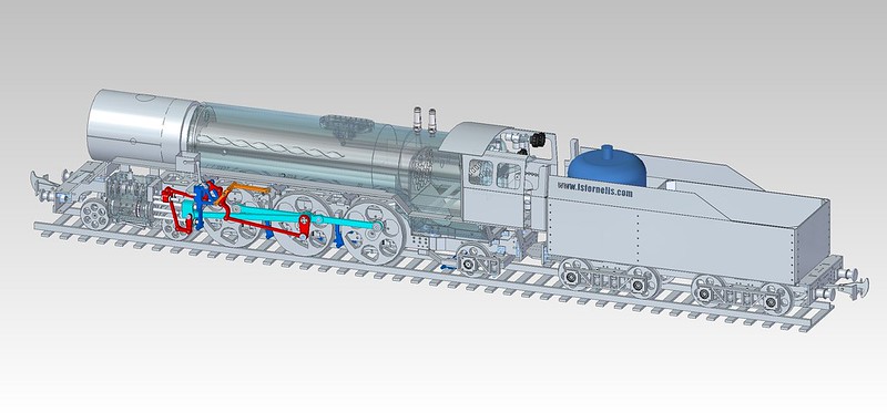 LocomotiveAssembly LocomotiveAssembly by joan lluch, on Flickr The picture shows the overall look of the locomotive with added colours to identify the transmission rods, valve gear, brakes and reverse link. The boiler cladding and barrel is made transparent to show the steam and water pipes inside. As a mater of scale, a regular 2.75 Kg refillable 'CampingGaz' butane container is shown at the front-most part of the tender. |
|
|
|
Post by joanlluch on Sept 18, 2015 16:21:29 GMT
THE FRONT BOGIE. The bogie design was made as per the following design drawings 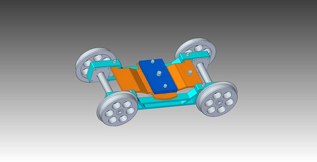 BogieAssemblyAlt2 BogieAssemblyAlt2 by joan lluch, on Flickr  BogieAssemblyAlt BogieAssemblyAlt by joan lluch, on Flickr There are two particularities on this design. 1 - The wheels with their axles are directly attached to lateral frames that move up and down along with the wheels through self aligning ball bearings. This differs from a classical locomotive bogie design where the wheels are suspended by springs and axleboxes to the frames. In my loco design the frames (cyan) are suspended through compression springs to a sub frame (orange) that it turn is linked to the locomotive frames (dark blue). No axleboxes are used, so no lubrication is required there. 2 - The bogie subframe (orange), and in fact the entire bogie is able to move sideways and to rotate with vertical axis with respect to the locomotive frames. This is similar to the movement that a classical bogie would do. In my case, the required degrees of freedom for the bogie are granted by a lever (red) that joins the locomotive frames (dark blue) with the bogie subframe (orange) through two spherical bearings. Two extension springs pull the bogie towards the centre line of the locomotive for guiding purposes. This mechanism avoids the need for sliding parts on the bogie while still behaving like a classical design. Any wear might be produced on the mentioned bearings that are easily replaceable and no lubrication is required at any time during its life. |
|
|
|
Post by joanlluch on Sept 18, 2015 16:29:32 GMT
The following pictures show the parts for the locomotive bogie and the thing already assembled and on the tracks. 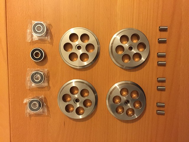 Bogie wheels Bogie wheels by joan lluch, on Flickr  Untitled Untitled by joan lluch, on Flickr 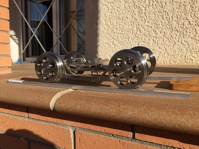 Bogie Bogie by joan lluch, on Flickr 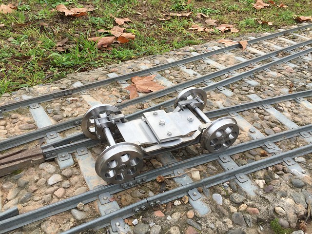 Bogie on the track Bogie on the track by joan lluch, on Flickr After making the bogie I realised that I could have simplified even further its design by incorporating wheel bearing housings directly onto the lateral frames (cyan). This would have avoided a number of parts that required a mill and lathe. I have used this simplified approach for the design of my locomotive tender bogies, as they are conceptually the same except that of course no side play movement will be allowed on them. |
|
|
|
Post by joanlluch on Sept 18, 2015 16:40:05 GMT
LOCOMOTIVE FRAMES Frames and all related parts were laser cut to final sizes except the front, back and top stretchers which relevant faces were adjusted to final size by CNC milling. Some threaded holes were made as well after receiving the frames. The following picture shows the laser cut parts the day that I collected them from a local laser cut service.  Laser Cut Frames and more Laser Cut Frames and more by joan lluch, on Flickr Next the basic locomotive frames assembled together. 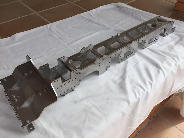 Bancada Bancada by joan lluch, on Flickr |
|
|
|
Post by Roger on Sept 18, 2015 16:45:01 GMT
It's great to see 3D models become a big pile of shiny parts, and finally coming together like that. You must be very pleased with it.
|
|
|
|
Post by joanlluch on Sept 18, 2015 16:48:58 GMT
LOCOMOTIVE WHEELS AND AXLES Wheels were water jet cut to oversize and further CNC machined to the final shape. The following picture shows a couple of wheels as collected from the water jet cut service. 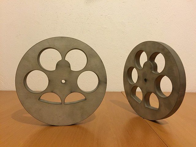 Unmachined wheels Unmachined wheels by joan lluch, on Flickr Next two pictures show the wheels already finished along with some related parts. First picture is the driving wheels and second one are the coupled wheels. 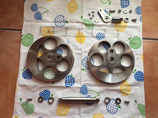 Eix Principal Eix Principal by joan lluch, on Flickr  Eixos acoblats Eixos acoblats by joan lluch, on Flickr |
|
|
|
Post by joanlluch on Sept 18, 2015 17:04:54 GMT
RETURN CRANK, DRIVING PINS AND WHEEL COUNTER-WEIGHTS The wheel axle ends and driving pins ends were made to be square to fit in similarly shaped holes on the wheels. Since the squared holes were made in one single setup by CNC milling, they are made to perfect dimensional accuracy and at the exact right place. Square ends on the axles means that setting opposed wheels at exactly 90 degrees is straightforward. The counter-weights on the wheels were determined by empirically placing a 'virtual' weight at the driving pin location equivalent to the rods weight and then protruding a virtual shape on the wheel until its centre of gravity went at exactly the centre of rotation. At the time I took a picture of that procedure for both the driving wheels and the coupled wheels. 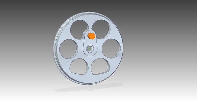 WheelBalanceTestCoupled WheelBalanceTestCoupled by joan lluch, on Flickr 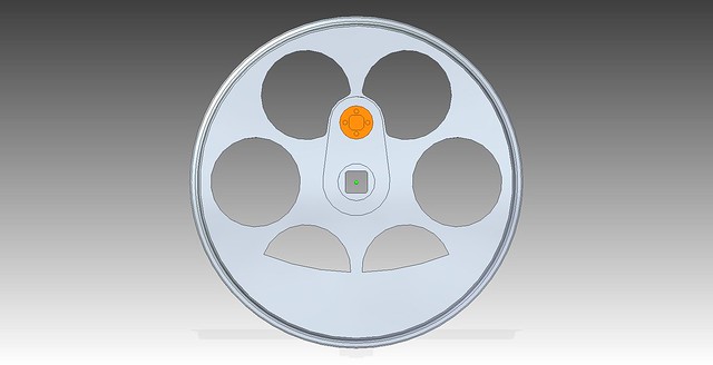 WheelBalanceTestDriving WheelBalanceTestDriving by joan lluch, on Flickr The return crank was made to fit using square ends in one unique possible position as determined by the valve gear geometry (to be discussed later). The following pictures show the way the return crank is fixed to the driving pin. 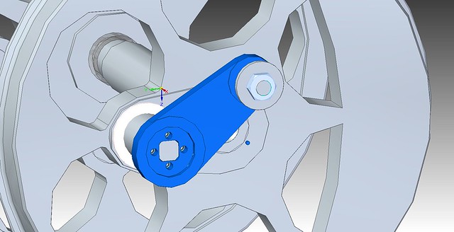 MainAxleWithWheels MainAxleWithWheels by joan lluch, on Flickr 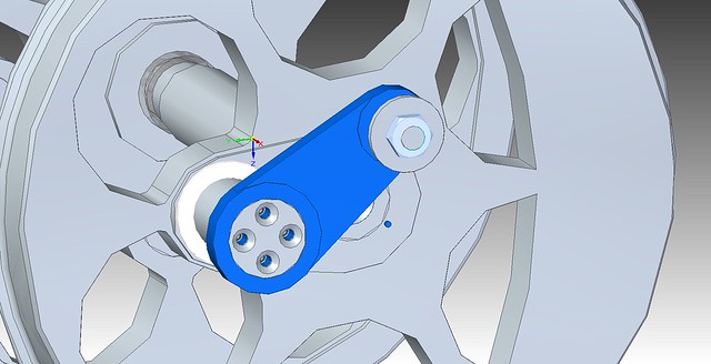 MainAxleWithWheels2 MainAxleWithWheels2 by joan lluch, on Flickr |
|
|
|
Post by joanlluch on Sept 18, 2015 17:20:09 GMT
AXLE BOXES For some reason I did not keep CAD captures of the design. I could take them now, but I'd rather advance on this series of posts to get earlier to the current locomotive state. I still can show several pictures of the parts already made and partial assemblies of them. 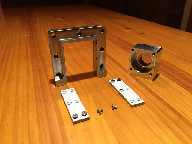 Patins Suspensio Patins Suspensio by joan lluch, on Flickr 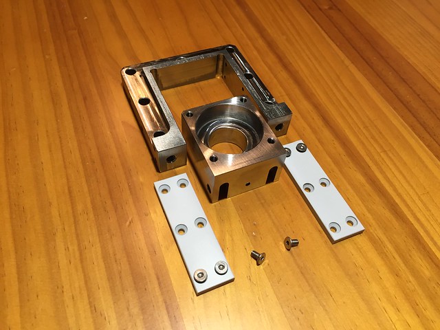 Patins Suspensio Patins Suspensio by joan lluch, on Flickr  Bastidor Bastidor by joan lluch, on Flickr 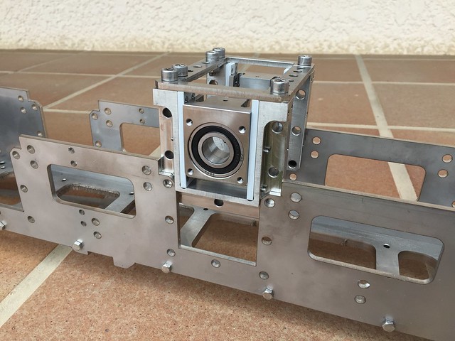 Caixes de coixinets Caixes de coixinets by joan lluch, on Flickr 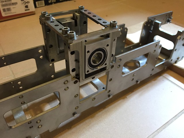 Caixes de coixinets Caixes de coixinets by joan lluch, on Flickr The sliding pads were made of Ertalite TX, which is a high tech plastic material with a low coefficient of friction with auto lubrication properties which is designed for bearings. |
|
|
|
Post by Roger on Sept 18, 2015 17:22:06 GMT
Hi Joan,
I have a couple of CAM questions for you. The number of facets on the holes in those last wheel pictures is very small, ie the circles have long flats on them. Is it like that to speed up the display? I find my system works fine with quite fine display values, and I never see a view like that.
I'd also like to know what form of data you send to your subcontractors for water jet cutting and CNC machining.
|
|
|
|
Post by joanlluch on Sept 18, 2015 17:24:20 GMT
LOCOMOTIVE SUSPENSION For the locomotive suspension, I chose a mechanism that would allow me to adjust the locomotive height from the bottom. This in turn is the most stable approach for a loco suspension because the axle box is pulled from the bottom as opposed to pushed from the top. These are some relevant pictures: 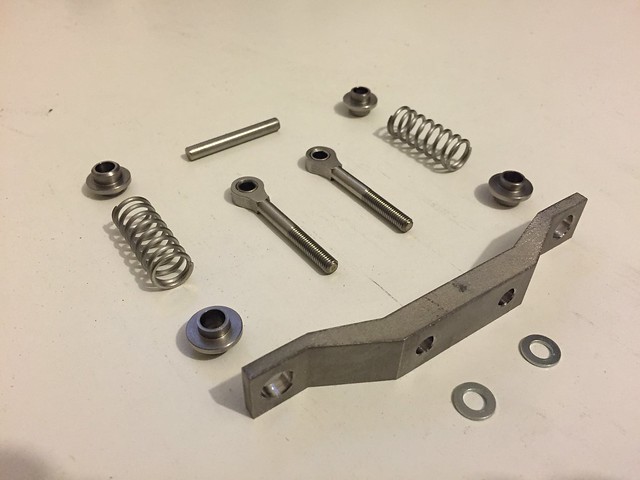 Bastidor Bastidor by joan lluch, on Flickr 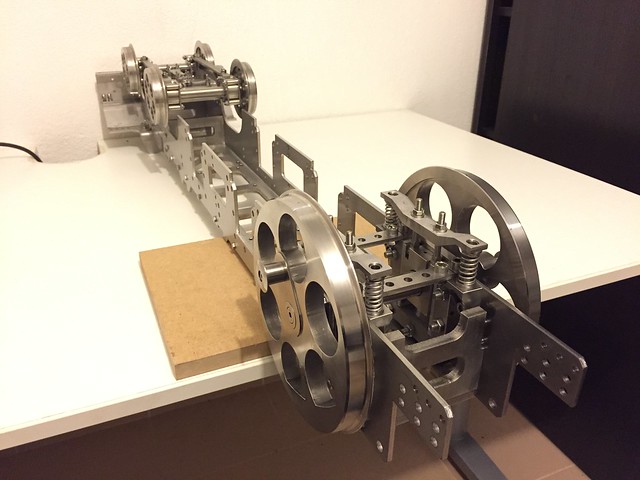 Bastidor Bastidor by joan lluch, on Flickr  Bastidor Bastidor by joan lluch, on Flickr 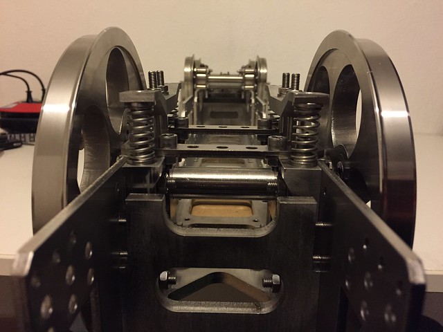 Bastidor Bastidor by joan lluch, on Flickr |
|
|
|
Post by joanlluch on Sept 18, 2015 18:02:11 GMT
Hi Joan, I have a couple of CAM questions for you. The number of facets on the holes in those last wheel pictures is very small, ie the circles have long flats on them. Is it like that to speed up the display? I find my system works fine with quite fine display values, and I never see a view like that. I'd also like to know what form of data you send to your subcontractors for water jet cutting and CNC machining. Hi Roger, I possibly do not have a proper explanation for that, but I found that If I open a part and then that part is shown in an assembly then the flats on circles disappear and circles are shown just right. However if I open an assembly directly then the flats are shown until I explicitly open the parts alone. I suppose this is something the system does to optimise the speed of onscreen rendering. In practice, you are almost all the time working with sets of parts in assemblies that you have just drawn or you have opened, so the flat lines do not usually show (in any case it's easy to remove them by just opening the affected part). The flats only show in the parts you are not working with!! . I guess that the pictures you refer were opened one day just to take the jpg capture and I did not realise the parts were not fully rendered. I recall that I captured the pictures when you were making your return crank and I posted them on your thread. At the time, I possibly was working on another section of the locomotive and these individual parts were not open in the environment, so that's why they might show jerky. If you look at the washer on top of the return crank, it does not show that flat artifacts, so I assume that washer was already in use and loaded into the system at the time. For laser cutting and water cutting I just send a 2D autocad file (dxf format) and specify the material and the sheet width with a annotation in the same file. For water jet cutting I must also specify the cutting speed. This has to do with the finish of the cut surfaces. The inner faces of the wheels were cut at a speed of 30%. The lower the speed the best the result, 100% speed is cheaper but you get a significantly 'coarser' surface. Not sure about other services, but this is the way it works for the local one I use. For CNC machining I suppose there's a proper format that describes the way it must be made and what paths should the mill follow to complete each task. I assume this is what you do. But I am not familiarised with that and I just generate 2D drawings with dimensions and tolerances on the parts. Then submit them to the service as dxf files. Then they convert or enter the appropriate data into their machines. In all cases, I have a talk or make a visit to them to define which dimensions are the important ones. While talking I am also interested in knowing the actual milling steps they propose to machine the parts so I can get assured that the surfaces that need to be accurate will be right. Still, there are errors and mistakes sometimes as you know. |
|
|
|
Post by andyhigham on Sept 18, 2015 18:55:38 GMT
I'm so glad this build series has been revived, It's so refreshing to see a different approach. Rogers speedy also shows different methods and mind set.
As I have stated before, too many model engineers forget the first 'E' in their club name xxSMEE stands for EXPERIMENTAL
|
|
|
|
Post by ejparrott on Sept 18, 2015 19:09:20 GMT
No E in our club name these days, used to be many many moons ago, before the current club came into existence I think
|
|
|
|
Post by joanlluch on Sept 18, 2015 19:15:28 GMT
At this point I brought the assembled frames and wheels to the track to check behaviour. See it on YouTube youtu.be/KIvxnu-Q3LgIt has not been mentioned before but the loco is designed to negotiate curves with radius larger than 9 meters. This is adjustable by placing specially designed flanges at the exterior sides of the axleboxes. The more width you place the less is the sideways play and the larger the required track curve radius. Next will be the (Baker) valve gear design. |
|


