|
|
Post by miketaylor on Oct 2, 2016 19:59:09 GMT
Joan,
Yes, I realise that the barrel/throat plate effect must be modelled; I was thinking of shortening the barrel to just a couple of centimetres.
Roger's suggestion looks like another possible workable approach. It might not be quite right for the roof of the firebox but should let you model the sides adequately.
Another possibility would be to take out the inner firebox and just close the base off with a single plate. This would let you model the whole outer skin.
Mike
|
|
|
|
Post by joanlluch on Oct 2, 2016 20:08:09 GMT
Thinking along the lines that Mike is proposing, could you cut the model in half along the centre line and just put a flat plate on the join so it's a closed volume? Hi Roger, that may certainly work to study the areas that are further from the top of the boiler. However, a flat flange will not work properly because that will want to bulge thus distorting the top of the boiler in a different way than a totally symmetric boiler. Another possibility is to constraint the edges of the half boiler to a fixed position, but this still will not behave the same as a fully drawn symmetric boiler because the top of it should be allowed to move (in fact it moves as more load is applied) The way the simulator works requires a minimum set of constraints that keeps the model in place. To set up the simulation, you add pressure forces to all the surfaces that should be subjected to them one by one. In fact the software does not have a notion of closed volume, you just add forces to surfaces and you are responsible to do it the right way. It is also required that the model is constrained at some point so that the forces you applied do not want to move the model away. I currently have fixed constraints at the very bottom of the firebox and I applied inward and outward pressure forces where appropriated. |
|
|
|
Post by joanlluch on Oct 2, 2016 20:18:04 GMT
Joan, I don't understand what you mean when you say only the middle row of stays are functioning. Looking at the stress colours it is clear that all three rows are supporting the side plates. Hi Mike, they are not. The stress colours that appear next to the upper and lower rows are due to bulges being developed there. These stays are not connected to the side plates. If you look at the video at full screen you can also notice that they are not part of the mesh (they appear grey coloured) , so they are not actually being computed by the simulator. Joan, When you refer to steess around the sr=tays I presume you mean the slight trace of red around each stay. I suspect that this is not importnat. Your model will not have included the effects of the welded joint at each stay where it attaches to the plates. The weld metal will form a fillet at each location and that should take care of the apparent stress concentration. Yes, this is right. And this tells that the presence of the filet you mention is important. Joan, You could check it by setting up a dummy model with a couple of stays and modelling the fillet to see what effect it had. Or just a single stay constrained to the ground attached to the centre of a circle to which you apply a pulling pressure. |
|
|
|
Post by miketaylor on Oct 2, 2016 20:27:32 GMT
Hi Joan,
Yes, I had begun to relaise that the upper and lower rows were not connected. It was the line of green that fooled me until I thought about it and realised that the blue areas between the stay rows were the points of contraflexure. It does suggest that the proposed locations for the upper and lower rows of stays are exactly right, and that possbly the two lowest stays are not required. I am curious about the slight traces of red which develop around the middle stays in the upper and lower rows at extreme pressure. Only just visible. Does the model have holes at the stay positions?
Thanks for the explanation about the way the model applies pressure. I had imagined it being modelled as an actual closed vessel.
Mike
|
|
|
|
Post by miketaylor on Oct 2, 2016 20:30:56 GMT
Continued.
To examine the effects on the stay/plate junction I think looking at a single stay model would be deceptive. Probably better to set up a grid of say, 5 x 5 stays, apply pressure and look at what happens around the middle of the group. Best to reproduce the typical stay spacing and eliminate edge effects.
Mike
|
|
|
|
Post by joanlluch on Oct 2, 2016 20:40:28 GMT
Hi Mike, Yes, the model has holes on the side plates just at the stay positions, but these holes are completely filled by the stays, so I think they have no effect where the stay is connected. BUT they show in the upper and lower rows as weaker spots just because there are holes there !
|
|
|
|
Post by joanlluch on Oct 15, 2016 8:07:56 GMT
The following pictures show the cylinder drain rigging already finished. Cylinder drain is actuated from the cabin by means of a bowden cable (commercially available). This part joins the two cylindrical arms. I latter on performed a longitudinal cut through this part to get more grip from the screws and prevent the arms to slip:  Braç Vàlvules Purga. Braç Vàlvules Purga. by joan lluch, on Flickr Drilling holes on one of the arms:  Braç Vàlvules Purga. Braç Vàlvules Purga. by joan lluch, on Flickr Initial assembly test:  Palanques drenatge. Palanques drenatge. by joan lluch, on Flickr Modified frame stay to make room for the cylinder drain rigging. (Yes, I can make a mistake even if I had it all drawn on 3D CAD)  Varis Fre i Purga Varis Fre i Purga by joan lluch, on Flickr Completed mechanism under the sun:  Varis Fre i Purga Varis Fre i Purga by joan lluch, on Flickr The bowden cable can be seen from this view:  Varis Fre i Purga Varis Fre i Purga by joan lluch, on Flickr Detail of one of the drain valves:  Purga Purga by joan lluch, on Flickr Drain valve arm being machined:  Purga Purga by joan lluch, on Flickr Completed assembly:  Purga Purga by joan lluch, on Flickr The geometry of the lever connecting both valve arms at one side is designed to find an end of travel exactly at the 45 degress position of the valves. So essentially, this is what determines the ultimate travel of the whole mechanism. This simplifies the adjustment of the bowden cable which travel gets totally defined. |
|
|
|
Post by joanlluch on Oct 15, 2016 8:18:31 GMT
Now, I have a question:
I used viton o-rings to create the required sealing between the cylinder block and the drain valves. This allows me to keep the valves screwed at the right position while at the same time preventing them to leak or move or wanting to unscrew. This works, but I do not like the look of these o-rings smashed under the valves.
How are drain valves normally fixed to the cylinder?. Any suggestion that would work for my build?. I do not want to solder or glue them or to use any other essentially irreversible way to fix them. I want that they can be easily disassembled just as everything else of my locomotive.
Thanks
|
|
|
|
Post by springcrocus on Oct 15, 2016 8:26:46 GMT
Counterbore the cylinder drain holes to lose the "O" ring into. You may still have a small witness but far less than shows now.
Steve
P.S. Lovely work, by the way.
|
|
Lisa
Statesman

Posts: 806 
|
Post by Lisa on Oct 15, 2016 9:14:19 GMT
Now, I have a question: I used viton o-rings to create the required sealing between the cylinder block and the drain valves. This allows me to keep the valves screwed at the right position while at the same time preventing them to leak or move or wanting to unscrew. This works, but I do not like the look of these o-rings smashed under the valves. How are drain valves normally fixed to the cylinder?. Any suggestion that would work for my build?. I do not want to solder or glue them or to use any other essentially irreversible way to fix them. I want that they can be easily disassembled just as everything else of my locomotive. Thanks I've always just used a bit of pipe joint compound on the threads, though you could add a locknut if you need to adjust the position. This is the stuff I use, which is also used on all the boiler fittings: www.blackwoods.com.au/part/05066405/compound-jointing-dixons-white-cln-750gm |
|
|
|
Post by Roger on Oct 15, 2016 10:14:22 GMT
Hi Joan,
Those 'O' rings look a very big section. If they were smaller then I think what Steve suggests would work. ie a pocket in the face of the cylinder. I would make a groove in the Male thread so that the 'O' ring could have a smaller inside diameter and also press against that. The 'O' ring could be as little as a 1mm section.
|
|
|
|
Post by joanlluch on Oct 15, 2016 10:55:25 GMT
Hi Joan, Those 'O' rings look a very big section. If they were smaller then I think what Steve suggests would work. ie a pocket in the face of the cylinder. I would make a groove in the Male thread so that the 'O' ring could have a smaller inside diameter and also press against that. The 'O' ring could be as little as a 1mm section. Hi Roger and Steve. Thanks for your suggestions. Yes, that o-ring looks ridiculously big, but I think it must be more than 1mm because the thread is M8x0.75. I can screw the valve at any half turn (the valve can be reversed) so this means every 0.375mm. I'm not sure if a 1mm o-ring would be squeezed enough and have enough friction surface to prevent the valve from unscrewing. Unless there's another way, the o-ring must fix the valve into position besides sealing. I like the idea of having a groove in the male thread though. Another complication is that the female thread on the cylinder is not deep enough to screw the valve fully, so I must solve that as well. |
|
|
|
Post by Roger on Oct 15, 2016 11:18:39 GMT
Hi Joan, Those 'O' rings look a very big section. If they were smaller then I think what Steve suggests would work. ie a pocket in the face of the cylinder. I would make a groove in the Male thread so that the 'O' ring could have a smaller inside diameter and also press against that. The 'O' ring could be as little as a 1mm section. Hi Roger and Steve. Thanks for your suggestions. Yes, that o-ring looks ridiculously big, but I think it must be more than 1mm because the thread is M8x0.75. I can screw the valve at any half turn (the valve can be reversed) so this means every 0.375mm. I'm not sure if a 1mm o-ring would be squeezed enough and have enough friction surface to prevent the valve from unscrewing. Unless there's another way, the o-ring must fix the valve into position besides sealing. I like the idea of having a groove in the male thread though. Another complication is that the female thread on the cylinder is not deep enough to screw the valve fully, so I must solve that as well. Hi Joan, You can choose to seal in the diameter if you like, that's what I've done on most of them. The bottom of the groove on the thread diameter can be one surface, and the inside diameter of the pocket can be the other. If you use 15%-20% compression on the 'O' ring, you can use a 1.5mm section. I'd need to see it modelled to be sure it would fit ok. If you need the face of the flange to make one sealing face and the bottom of the pocket being the other, you have a problem with the size of the flange and interfering with the screws holding the cylinder cover on. You would need to get the pocket diameter right, so I don't think this is something you can do on the mill unless you buy a boring head, something like thisPerhaps you can make the hole for the female thread deeper? Is there enough metal without breaking through? You can use a modified tap that's been ground flat across the end to get the thread deeper but you have to be gentle. |
|
|
|
Post by joanlluch on Oct 15, 2016 15:16:47 GMT
Hi Roger, thanks for your reply If you need the face of the flange to make one sealing face and the bottom of the pocket being the other, you have a problem with the size of the flange and interfering with the screws holding the cylinder cover on. Please would you elaborate on this? I do not quite understand what you mean. ...you can do on the mill unless you buy a boring head, something like thisThanks for that. Perhaps you can make the hole for the female thread deeper? Is there enough metal without breaking through? You can use a modified tap that's been ground flat across the end to get the thread deeper but you have to be gentle. The hole is deep enough and it was all correctly modelled, but It turned to be that the allowance that I gave for threading was not enough and the threaded section resulted shorter than I expected. I think the problem is that this is a relatively rare thread and I borrowed the only available tap that was not the right kind for blind holes. I used it anyway but it did not get very deep. So basically I suppose I just must find the right tap. |
|
|
|
Post by joanlluch on Oct 15, 2016 15:39:28 GMT
I have finished the brakes. Brakes are meant to be used only on stationary, not generally as a means to stop the loco while running. I use a bicycle brake cable for that. Brakes can be set in two stable positions, on and off. I made a device (brake actuator) that makes this possible. These are some parts of the brake actuator:  Varis Fre i Purga Varis Fre i Purga by joan lluch, on Flickr This is the brake actuator in the "brakes off" position:  Varis Fre i Purga Varis Fre i Purga by joan lluch, on Flickr This is the brake actuator in the "brakes on" position:  Varis Fre i Purga Varis Fre i Purga by joan lluch, on Flickr The brake actuator works by slightly overtaking the neutral position as the cable is pulled. So the cable tension keeps it in a stable position when on. The weight keeps it stable in the off position when the cable is free. This is a partial assembly of it:  Varis Fre i Purga Varis Fre i Purga by joan lluch, on Flickr This is where the brake cable begins in the brake actuator.  Frens Frens by joan lluch, on Flickr I have not taken a picture of it, but the part just above pivots on the hole that is seen on the triangular part of the partial assembly photo. |
|
|
|
Post by joanlluch on Oct 15, 2016 15:53:02 GMT
The end of the braking cable goes here:  Frens Frens by joan lluch, on Flickr And from there to the brake rigging:  Frens Frens by joan lluch, on Flickr This is a general view of the brake rigging:  Frens Frens by joan lluch, on Flickr The brake rigging is designed to work in a completely balanced way with the minimum of rods and levers and no need for individual adjustments of brake pad positions. Every one of the 6 brake pads receives exactly 1/6 of the braking force. The rigging uses quite an unique design. This is a photo of the brake rigging itself (my daughter acts as my assistant).  Frens Frens by joan lluch, on Flickr |
|
|
|
Post by joanlluch on Oct 15, 2016 16:06:53 GMT
Now, these are some details of the remaining elements of the braking system: 3D Printed brake pads by Shapeways  Sabates Fre Sabates Fre by joan lluch, on Flickr Finishing: 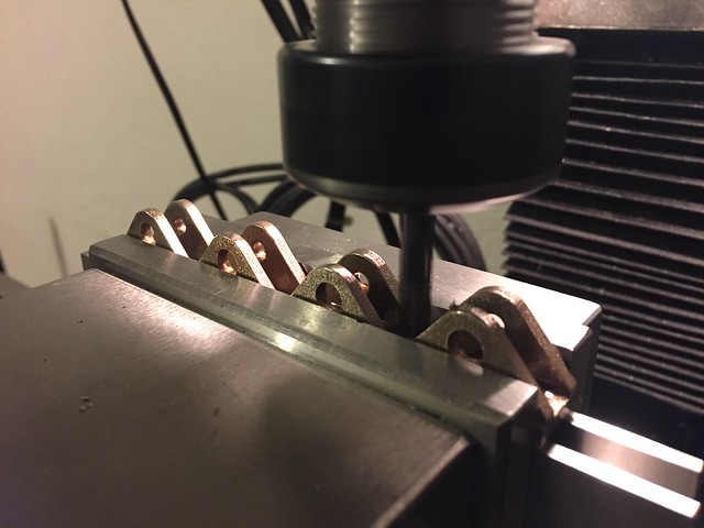 Frens Frens by joan lluch, on Flickr Brake arms assembly. I used o-rings to enable freedom of movement without being loose, particularly sideways movement of the pair of brakes for same axle. This is required because the loco was designed with a significant axle sideplay to negotiate the short radius curves of local circuits.  Frens Frens by joan lluch, on Flickr More assembly details:  Frens Frens by joan lluch, on Flickr  Frens Frens by joan lluch, on Flickr  Frens Frens by joan lluch, on Flickr  Frens Frens by joan lluch, on Flickr  Frens Frens by joan lluch, on Flickr  Frens Frens by joan lluch, on Flickr And finally, this is the testing setup:  Frens Frens by joan lluch, on Flickr The brake actuator will obviously go to the locomotive cabin once finished. It is big enough and easy to operate specially now that I have shaky and painful hands due to my illness, so I am very pleased with it. |
|
|
|
Post by Roger on Oct 15, 2016 16:17:27 GMT
Hi Roger, thanks for your reply If you need the face of the flange to make one sealing face and the bottom of the pocket being the other, you have a problem with the size of the flange and interfering with the screws holding the cylinder cover on. Please would you elaborate on this? I do not quite understand what you mean. On this model, the far left part is threaded. The 'O' ring sits in a groove where the thread has been machined away so it's smooth for the 'O' ring to seal against. The boiler fitting has a pocket that the 'O' ring squeezes into to make the seal. The situation is similar to yours. Perhaps you can make the hole for the female thread deeper? Is there enough metal without breaking through? You can use a modified tap that's been ground flat across the end to get the thread deeper but you have to be gentle. The hole is deep enough and it was all correctly modelled, but It turned to be that the allowance that I gave for threading was not enough and the threaded section resulted shorter than I expected. I think the problem is that this is a relatively rare thread and I borrowed the only available tap that was not the right kind for blind holes. I used it anyway but it did not get very deep. So basically I suppose I just must find the right tap. Don't worry if you can't get a Bottom tap, you can just grind one down from any other type. Many taps have a point and a very long 'lead in' that usually gets removed when I get them because on a short thread you can barely get the tap started before it hits the bottom. I use a Diamond Needle file to put a little clearance back from the cutting edge when the tap is ground back to the full diameter. |
|
|
|
Post by joanlluch on Oct 15, 2016 16:54:49 GMT
Roger, I still do not see the point. What you showed modeled in your post above is a different scenario, than my drain valves no?
|
|
|
|
Post by Roger on Oct 15, 2016 17:20:47 GMT
Roger, I still do not see the point. What you showed modeled in your post above is a different scenario, than my drain valves no? The problem you have is that you're trying to seal on the face of the flange, but the flange is too small to do that. All I'm showing is that there's another way to seal on the diameter that overcomes that problem. If you seal on a diameter where you remove the thread and on the inside of a pocket, the flange just screws up to the face and doesn't compress the 'O' ring. |
|


