johnthepump
Part of the e-furniture
 Building 7 1/4"G Edward Thomas
Posts: 494 
|
Post by johnthepump on Dec 7, 2019 17:03:39 GMT
A Month ago one of the men in the men in sheds team that I belong to but have not attended since being ill, asked if I could make up a pipe flange to connect to a cooling tank. He supplied two mild steel disk 6mm thick and a short piece of 2 1/2" bore pipe. I got on with the machining of the flanges that evening and drilled the 4 bolt holes, but I told him I wasn't sure how I would get on with welding since losing some sight in my right eye. The pipe was Galvanised so I machined that off in the area to be welded and chambered the other end as requested. I decided to use Tig welding with the 100 amps set and foot pedal control I set off not knowing whether I was going to make a pigs ear of this job, much to my surprise it turned out OK it wasn't easy and everything is a little more difficult, needless to say having bought a new welder last year I'm delighted I'm still able to use it.  03.12.2019 03.12.2019 by John The Pump, on Flickr However this wasn't the end of the story, for when he returned the job to site it was found the pipe size should have been 2" bore, so the job returned and I was asked if there was any way I could fit the smaller pipe to the clamping flange? not withstanding it past through the hole in the flange with 1/8" clearance all round. I decided to try to swage the end of the pipe using the flypress and this work well.  03.12.2019 03.12.2019 by John The Pump, on Flickr And after machining and welding the jobs a good one.  03.12.2019 03.12.2019 by John The Pump, on Flickr  03.12.2019 03.12.2019 by John The Pump, on Flickr Regards John. |
|
johnthepump
Part of the e-furniture
Building 7 1/4"G Edward Thomas
Posts: 494
|
Post by johnthepump on Dec 10, 2019 15:58:14 GMT
While looking through various threads, I came across a tool height setting DTI on sheet 19 of 'Oily Rags Excitement'. Having a similar indicator for years and wondering if I would ever use it thanks to Dazza, I have turned this pile of bits.  10.12.2019 10.12.2019 by John The Pump, on Flickr Into this 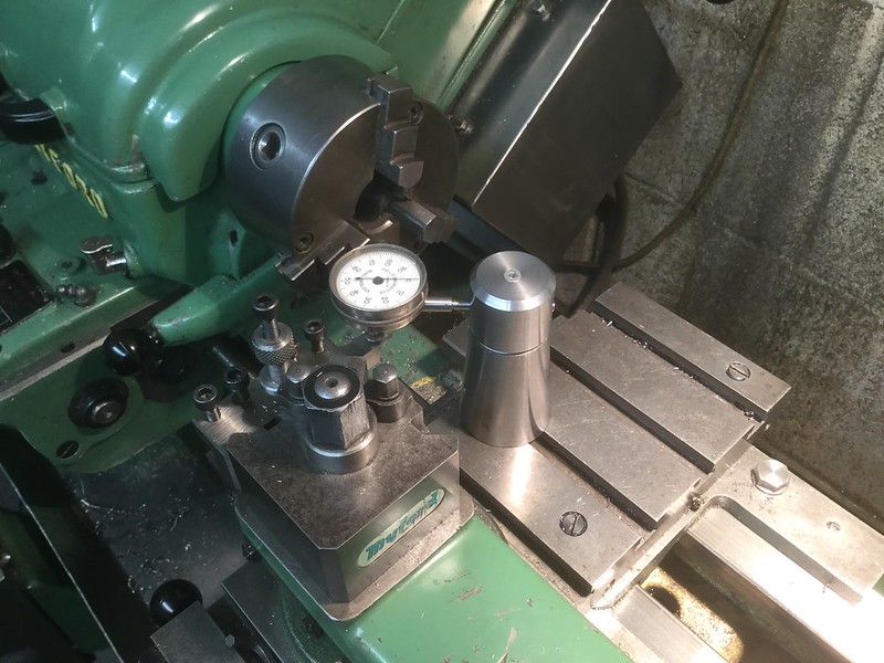 10.12.2019 10.12.2019 by John The Pump, on Flickr The tapered part was to be something to do with a type of anchor bolt, I had made some prototypes in smaller sizes but these ones are threaded 24mm x 3mm pitch and were put to a CNC shop. Now the drawings showed the dimensions but not the method. The Guy popped in to see me and asked how to do the next stage of the job. It needed a sacrificial (chucking) piece on the small end, so he left the 3 parts and the short length of studding in my odds box and left to start again. Regards John. PS if I knew how to do it I would have put a link to Oily rags one ? |
|
stevep
Elder Statesman

Posts: 1,070
|
Post by stevep on Dec 10, 2019 17:12:54 GMT
|
|
jem
Elder Statesman
Posts: 1,067
|
Post by jem on Dec 10, 2019 17:57:38 GMT
I too have copied Oily-rags height gauge but a bit cruder, as my stump was a bit of pipe filled with lead, but it is such a useful piece of equipment, so my thanks go to Oily-rag.
best wishes
Jem
|
|
|
|
Post by Jim on Dec 10, 2019 23:28:34 GMT
This is the very simple height gauge I've used for ages. I think I got the idea from one of the ME mags but it's so long ago now i can't remember.  The underside of the height bar has a flat ground on it for the tool tip to register against.
Cheers Jim.
|
|
dscott
Elder Statesman
Posts: 2,438
|
Post by dscott on Dec 10, 2019 23:51:46 GMT
Wonderful!! I must get into full production after Christmas and make a full set of 7. Each Lathe needing one each.
The same for the bits!! In cabinets. Two lathes and the Dore Westbury sharing the Myford set of chucks.
My current conclusion is that we desperately need a WORKSHOP EXTENSION>
David and Lily.
|
|
|
|
Post by Oily Rag on Dec 11, 2019 20:22:01 GMT
John and others, I am chuffed that my height thingie post has been useful. The beauty is it is very easy and fast to use and very accurate to 0.01mm, compared to the usual touch bar type of gauge, which is important as the work gets smaller. Sharing is what makes life fun.
Cheers
|
|
|
|
Post by Oily Rag on Dec 11, 2019 20:24:37 GMT
This is the very simple height gauge I've used for ages. I think I got the idea from one of the ME mags but it's so long ago now i can't remember. The underside of the height bar has a flat ground on it for the tool tip to register against.
Cheers Jim.
Eccentric tool's Diamond tool holder is the Bee's Knees, eh ! |
|
|
|
Post by Jim on Dec 11, 2019 20:51:25 GMT
It certainly is the bees knees Dazza. I have two, though the most recent from Eccentric will cut both to the left or the right depending on how you set it up in the tool post so it's in constant use. The earlier Diamond cutter is now used for thread cutting when the need arises.
I do have tipped tooling but rarely use it as the Eccentric cutter sharpened does a all I want and with the jig is a doddle to sharpen.
Jim
|
|
johnthepump
Part of the e-furniture
Building 7 1/4"G Edward Thomas
Posts: 494
|
Post by johnthepump on Dec 31, 2019 21:19:17 GMT
As my health has slowly improved I have been able to spend more time in the workshop and I have got back to my loco build, the motion brackets have been partially machined enough to mount them onto the frames. The drawings are very scant as far as some dimensions. To this end I have temporarily fitted the cylinder with the rear covers which are reamed 3/8", so that A length of silver steel can be used for reference measurements.  30.12.2019 30.12.2019 by John The Pump, on Flickr As I have made the coupling and connecting rod to the post 1977 style rather than the marine rods, this means a redesigned cross head. Regards John and Happy New Year to all. |
|
uuu
Elder Statesman
your message here...
Posts: 2,815
|
Post by uuu on Sept 8, 2020 8:43:03 GMT
It's been such a long time since there was a Pump House update here. I could not visit during lockdown, and have just been occasionally since things have eased. John is not firing on all cylinders yet, but he's still helping out all comers with a wide variety of problems/projects. Here's a case in point. A local restoration project is trying to resurrect two giant stationary engines, that have been stationary for too long. They are air-started, so there's an auxiliary engine and compressor to charge up the air tank. One of the casings had a threaded fitting sticking out, with no obvious purpose for it. John figured out it was for an oil cup, so set about making a suitable replacement:  IMG_1522 IMG_1522 by Wilf, on Flickr The threaded fitting is original, the tap is from the oddments bin and John has made the elbow and cup. Wilf |
|
uuu
Elder Statesman
your message here...
Posts: 2,815
|
Post by uuu on Sept 8, 2020 9:26:59 GMT
The IWMES "Hercules" has been in and out of the Pump House having its poor performance investigated. John has made some temporary eccentric rods, slightly different length from the original. But before these could be properly tested, some complete ***** decided to coax the piston back into the bore with a screwdriver, breaking the Clupet style ring! Many of you will have seen the Steam Workshop how-to-do-it video - links have been posted before. So John thought he'd have a go. Step 1 - turning the basic ring:  IMG_1507 IMG_1507 by Wilf, on Flickr Not having a long enough blank to chuck, John drilled a hole in it and mounted on an arbour, to turn inside and outside diameters. The loco's bore is 2.005" - the size of the blank was worked out using the guidance in the video. Step 2 - slitting (failure):  IMG_1508 IMG_1508 by Wilf, on Flickr The first attempt at slitting, using the rotary table in the mill, went badly. The slitting saw drifted way off line. Here's how it's supposed to be done (a still from the video):  Capture Capture by Wilf, on Flickr You'll see they've not got a perfect line-up either. We found that cutting in three shallow passes made a big improvement. Also we didn't hold it as shown, and cut our fingers like the chap in the video. Step 3/4 - finishing the slitting with a hand saw - turning the ring inside out:  IMG_1510 IMG_1510 by Wilf, on Flickr Here's the little saw John used to square up the ends of the partial slit, and cut the diagonals - and the ring after flipping round, but before finish-filing. Edit - that saw was for the diagonals only - a piercing saw was used to square up the ends. Step 5 - heat treatment:  IMG_1512 IMG_1512 by Wilf, on Flickr The picture shows the ring, mounted on its stretcher, having been heated to red-heat. Step 6 - turn back the right way:  IMG_1513 IMG_1513 by Wilf, on Flickr The ring's now back the right way round, standing on the stretcher, that expanded the ring during the heat treatment so it sets with the coils open a bit on diameter, but sprung together side-by-side. Step 7 - finish-turning the width:  IMG_1516 IMG_1516 by Wilf, on Flickr The ring is mounted in a jig, just held in by its own spring, and turned true. You'll see this is using one of those "diamond" turning tools by Eccentric Engineering. Step 8 - finish-turning the diameter:  IMG_1523 IMG_1523 by Wilf, on Flickr Mounted in another jig - compressed first on diameter with an outer ring, then clamped on the sides. This jig was made from a hard bit of cast iron, which destroyed the tip of the "diamond" turning tool, so back to carbide inserted-tip. and the result:  IMG_1524 IMG_1524 by Wilf, on Flickr Step 9 - mount on piston (with old, broken ring in front):  IMG_1525 IMG_1525 by Wilf, on Flickr You'll see the thickness of the coils isn't particularly even - but it will work well enough, I'm sure. Just the one ring - we weren't going to remake the piston. Here's just a parting shot of the jigs etc. used in the manufacture:  IMG_1527 IMG_1527 by Wilf, on Flickr We got the piston back in to the loco and ran it up on air. It went easily on only 10 lbs pressure, but a little roughly, and with a horrid whistling noise. It will go back to the club now, for some bedding in on steam. So yes - you can make Clupet style rings yourself - no one step is particularly difficult. It's a bit of a nervous moment when you stretch the ring over the piston at the end! Wilf |
|
|
|
Post by Roger on Sept 8, 2020 11:21:56 GMT
Excellent, that's a cracking job! I never accept that there's some 'magic' that lets others do something that the rest of us lesser mortals couldn't.
Slitting saws have a mind of their own unless you're supporting out near where you're cutting. There's nothing so stop you making a couple of Steel supporting washers to put either side of the slitting saw to make it more rigid.
|
|
uuu
Elder Statesman
your message here...
Posts: 2,815
|
Post by uuu on Sept 19, 2021 12:50:39 GMT
It's a year since the last posting here. Things have been quiet, but regular weekly sessions have resumed, complete with pub visit afterwards. This week, a visitor brought in his paddle steamer engine, which runs OK on air, but has a tight spot. We pointed out the rub mark on the frame where the crankshaft counterweight was touching. Obvious, I suppose, but he hadn't spotted it. We're just finishing off the new eccentric rods for the club loco. The originals were made to drawing, but the new ones are made to fit, in the hope that the engine runs better. Earlier in the day, John and I had met a club member who asked us to make some expansion links for his 1" steam lorry, using CNC. The club chap had started to make one, but the part had slipped when cutting the slot, which put him off a bit. I made these at home, rather than at the Pumphouse. They use 1/16" gauge plate. I made a spare one.  WIN_20210919_13_35_51_Pro WIN_20210919_13_35_51_Pro by Wilf, on Flickr Wilf |
|
|
|
Post by Jim on Sept 20, 2021 6:10:20 GMT
It's nice to see this group back in action. Just reading the various posts is always a pleasure and I get a feeling the atmosphere at the Pumphouse is akin to the TV series 'The Repair Shop. Having a pint of soothing ale at the local sounds a grand idea to me. Take care and stay safe Jim.
|
|
uuu
Elder Statesman
your message here...
Posts: 2,815
|
Post by uuu on Oct 31, 2021 16:41:45 GMT
Continuing the occasional updates on the Pumphouse, with some details of last week's efforts:
During the day we fitted the club loco's new expansion rods, and gave it a steam-up. It needed a new ticket, so the various checks on safety valves, injector and pump performance were done before we could give it a proper go. Relief all round as the beast went much better than before, with even beats and able to haul three trolley loads round.
In the evening, a sorry looking Lister cylinder head turned up. From a two-cylinder engine, one of the inlet or outlet flanges had been left in place with the pipe hacked off, the bolts were seized. The other side had one stud sheared off. And the spark plug was seized in. We bolted it to an angle plate so it could be held firmly and the reluctant bits attacked. With some WD40 and heat, the seized bits were removed. And the sheared stud was drilled out in the mill.
Turning to John's own engine (at last!) - we made a disappointing discovery. Edward Thomas can be made with marine-style rods, or locomotive ones. The wheels had previously been fitted for marine, but John wanted locomotive, so new crank pins had been made to suit - and the wheels quartered onto the axles. With the cylinders and newly-made motion brackets erected with temporary slide bars, we tried on the connecting rods and cranks. They didn't line up! The cranks ended up inboard of the slide bars by about 50 thou.
With non-standard cylinders, thicker than normal wheels, and different rods, something was bound to go wrong, I suppose. We scratched our heads for quite a while until we concluded that the previous crank pins (not made here) were also wrong and we had foolishly based the new ones on those.
So with a bit more head scratching, we devised a way to press them out of the wheels in an arbour press, whilst still attached to the axles.
No time to start on the new ones - the pub has taken to closing early if it runs out of customers, so we have to be sure to get there in time.
Wilf
|
|
johnthepump
Part of the e-furniture
Building 7 1/4"G Edward Thomas
Posts: 494
|
Post by johnthepump on Jan 11, 2022 20:11:05 GMT
For some while now Wilf has suggested that I should get back to posting on here. I did try a couple of days ago but I was unable to access flickr as the login had changed since I had last used it. Now that I have sorted it I will have ago. So to start with Wishing everyone a happy New Year. In the Pumphouse all sorts of bits and pieces have been sorted out and repaired, I will put up photos in due coarse, but to start with we have got back onto my Loco build (7 1/4 G. Edward Thomas) and the return cranks have now made.  09.01.22 09.01.22 by John The Pump, on Flickr |
|
johnthepump
Part of the e-furniture
Building 7 1/4"G Edward Thomas
Posts: 494
|
Post by johnthepump on Jan 15, 2022 18:53:40 GMT
Back in October. One of the Men in sheds team working on the restoration work at the old Browns golf coarse power pavilion said they had mislaid the strong back that held the fuel injector in the Ruston 6HR engine. The injector was away being checked over and serviced and been passed onto a mainland firm for this. Although I was one of the original member of the team I had not done anything on site since I was ill, but I said I would support them from the workshop. They wanted to try the injector from the large engine but the strong back fixing holes were a different spacing. So I made a new one.  Untitled Untitled by John The Pump, on Flickr I thought I would start my own brand mark on some of these little jobs, so I drew up a little oval similar tp a loco shed plate. This part as it turned out was all for nothing as the injector on the large engine was smaller and would not fit the smaller engine and when the correct injector came back from service it was found to be a much larger diameter and have the strong back was with it. The the firm who serviced did a wonderful job even taking the trouble to sand blast the strong back, the job came free of charge which was appreciated. |
|
samc88
Active Member

Posts: 42
|
Post by samc88 on Jan 16, 2022 23:14:31 GMT
That looks good,how did you do the brand marking?
|
|
johnthepump
Part of the e-furniture
Building 7 1/4"G Edward Thomas
Posts: 494
|
Post by johnthepump on Jan 18, 2022 17:48:49 GMT
That looks good,how did you do the brand marking? Hi Sam, I have a small CNC called a MicroMill. Regards John. 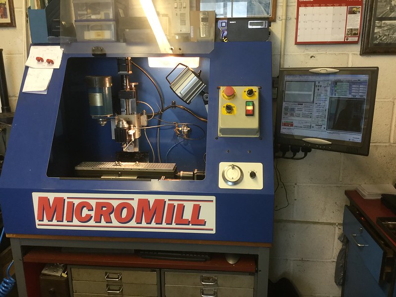 MicroMill MicroMill by John The Pump, on Flickr |
|


