|
|
Post by 92220 on Apr 11, 2017 15:09:39 GMT
Mike that's a superb bit of draughting!!! The fins and scoop don't really need to be cast as they are easy to make in sheet brass, but I leave that decision up to you. If you can do the castings, I'll darned well make them work after all that work you've done!! A very big 'Thank you'!
Bob.
|
|
|
|
Post by Roger on Apr 12, 2017 14:03:19 GMT
Are the curved deflectors there to balance the hydrostatic forces trying to pull the scoop into the trough?
|
|
|
|
Post by 92220 on Apr 12, 2017 17:50:48 GMT
Hi Roger.
I think you are right there. There doesn't seem to be any other reason. I had thought that they might be to prevent the scoop going too deep into the trough but they are set at an angle to each other and curved inwards, so couldn't be used as guides. Because they are curved, any water being driven upwards by the water scoop, would be deflected back to the trough. The way the fin sides are straight down at the front and curved at the rear, does seem to indicate that excess water is diverted back to the trough, rather than onto the track, in a controlled way. I've looked on the drawings and unfortunately nothing is written about how it works.
Bob.
|
|
44767
Statesman

Posts: 529
|
Post by 44767 on Apr 14, 2017 21:05:02 GMT
I Think that's correct. It must be an attempt to divert some of the spray back into the trough. I see on the drawing there is a ramp and extra links which move the scoop out of the way if it hits anything.
|
|
44767
Statesman
Posts: 529
|
Post by 44767 on Apr 23, 2017 8:30:24 GMT
I have produced the waxes for the water scoop main castings. they will be off to the foundry tomorrow afternoon. It may be possible to do the replaceable scoop as a casting or to have it integral with this casting but Bob has said he'd try making it himself from sheet metal. The pink parts are the sprues which I put on; it is too risky allowing the foundry to put them on as they have no idea what parts are important and how one might remove the sprue. In this case, they are attached at a point where they won't be seen and Bob will only have to fettle them with a die grinder or similar.  |
|
|
|
Post by 92220 on Apr 23, 2017 17:19:35 GMT
Mike they are brilliant!! You are a Star!!! I can't wait to get working on the castings!!
Bob.
|
|
stan
Seasoned Member

Posts: 110 
|
Post by stan on Apr 23, 2017 21:05:16 GMT
Hi Mike
Are you planning to cast a few for sale, as I would like a set for my 5" 9F please
Stan
|
|
44767
Statesman
Posts: 529
|
Post by 44767 on Apr 24, 2017 8:23:54 GMT
Hi Mike Are you planning to cast a few for sale, as I would like a set for my 5" 9F please Stan Stan, of course I can do other sets. There has been quite a bit of time gone into CAD modelling this so I'm more than happy to spread that effort. May I suggest though that, since this will not ever have to work (other than move), the parts are rapid prototyped in plastic? It will be much cheaper and no one will know once it has a coat of primer on it. Then the fins and scoop can be all printed as one in the same piece. They are a bit fragile to print and expect to come back from the foundry in one piece. |
|
|
|
Post by 92220 on Apr 27, 2017 12:58:22 GMT
Mike has done the castings now. Brilliant!! Here are some photos he sent me....     He can supply them as plastic mouldings at £93.00 per set or £150.50 for them cast in bronze. Bob |
|
|
|
Post by Geoff (Carlisle) on Apr 30, 2017 20:48:59 GMT
Hi Bob, the metal plate that precedes the mouth of the W.P.U, guides the water and is known as the 'Economizer'. Many years ago in the Model Engineer Mag , some chaps down south fitted a tender with a W.P.U. and made up some troughs and the W.P.U. worked loco hauled and also when it was pushed around by hand, but like I said my years ago.
Geoff (Carlisle).
|
|
|
|
Post by 92220 on May 1, 2017 8:06:06 GMT
Hi Geoff.
Thanks for that. I've got the drawing for the Water Scoop Deflector. It's easy to forget it until you look at the GA because there is no reference on any of the other water scoop drawings. It's very primitive, but worked.
Bob
|
|
|
|
Post by trainman on May 2, 2017 19:35:43 GMT
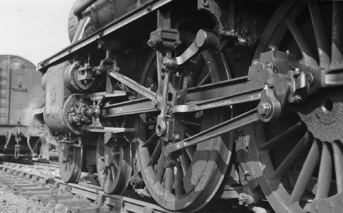
Just for info, below is a pic from 76017 showing the attachment of the fixed part of the scoop to the underside of the tender. Paul  |
|
|
|
Post by 92220 on May 6, 2017 8:28:44 GMT
Thanks for that photo Paul. I shall add it to my photo record.
The castings have just arrived. A great big 'Thank you' Mike. They are superb!!
Bob
|
|
44767
Statesman
Posts: 529
|
Post by 44767 on May 11, 2017 10:13:30 GMT
Here's a little more detail for the bronze castings.  The extra parts are the fins and the cover which shrouds the hinged part of the scoop. Nut and bolt detail is incorporated as it is intended to silver solder these to the main castings. The thin parts are still attached to a frame which makes handling the waxes much safer (for the wax!) |
|
|
|
Post by 92220 on May 11, 2017 10:40:37 GMT
Super bit of casting Mike!
Bob
|
|
44767
Statesman
Posts: 529
|
Post by 44767 on May 23, 2017 8:20:55 GMT
This has arrived from the 3D printers. They are the water scoop printed in a resin which is a much cheaper option than printing waxes and then having them cast. All detail is included this way as the nut and bolt detail was modelled as well. I have given them a coat of "photographic grey" primer to make the image better.   The hinge cover, however, was not drawn until after I sent this model to the printers so for those of you who have asked me to supply you with a plastic one, I will include a bronze one which can be attached with epoxy resin or similar. Future plastic ones will have this incorporated into the funnel. |
|
|
|
Post by 92220 on May 23, 2017 10:20:17 GMT
Lovely job Mike, seeing it with all the 'bells and whistles'! There is certainly a lot to be said for having it printed in resin!!
Bob
|
|
44767
Statesman
Posts: 529
|
Post by 44767 on May 24, 2017 10:40:25 GMT
The hinge cover arrived today. I love the way different processes tie up so closely!  |
|