|
|
Post by Roger on May 4, 2019 9:15:23 GMT
Hi Ed,
Before going too much further, would it be a good idea to start a dedicated thread to this topic?
|
|
|
|
Post by Roger on May 4, 2019 15:59:57 GMT
Yes you are right - I have been thinking the same thing, but it would mean the Terrier thread would die for some time, which would be a shame! Doubt that I could keep both going as multi-tasking is not my strong point!! HELLO everyone - I have started a new thread for the Princess - "3.5 inch gauge Princess Royal Rejuvenation" - it makes sense to do this but I will leave the above as it shows interested parties and some of your posts.
EdYou might be able to get a moderator to move the appropriate posts if you ask them. |
|
|
|
Post by terrier060 on Jul 13, 2019 21:53:11 GMT
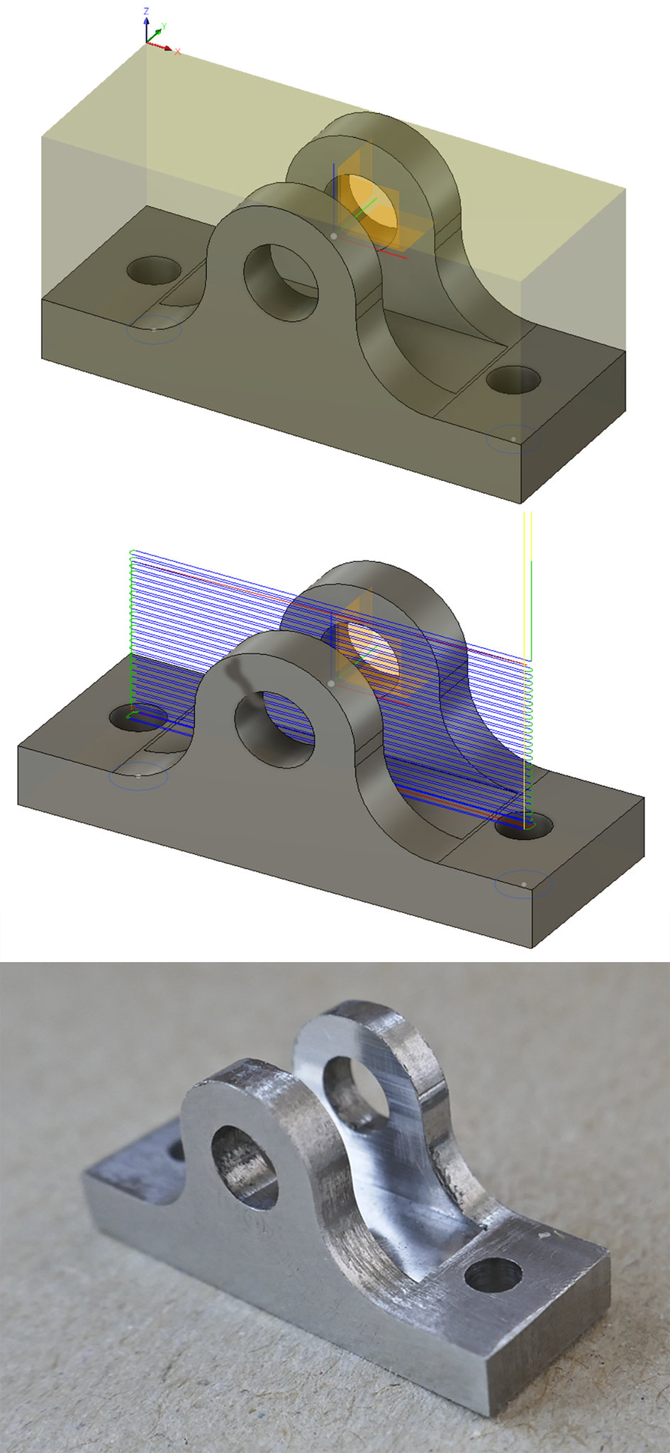
At Last - back to the Terriers. It seems like an age. Here are the stages in CNCing the bypass levers showing the tool paths. This is in free-cutting stainless and I am getting a lot more patient - Roger will be pleased with me! I am taking lighter cuts (15thou depth and 0.8 in/min feed). The cutter hardly makes a sound and gives nice clean chips. I leave it going and watch the tennis! I am using a 2mm cutter and first contour the piece (top left) followed by pocket to clear out the excess metal (top right and bottom left). This cuts at full depth without any trouble. Finally I use a spotting drill to mark the hole positions. I prefer to drill them after I have parted the levers off the bar. 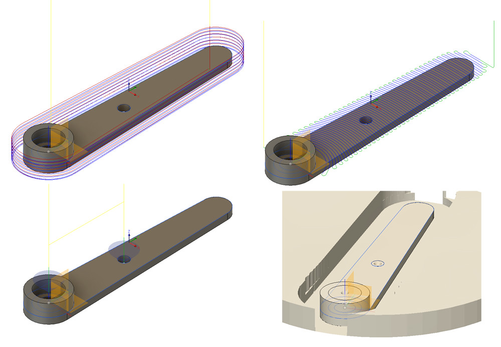 Bypass lever CNC diagrams Bypass lever CNC diagrams by ed cloutman, on Flickr 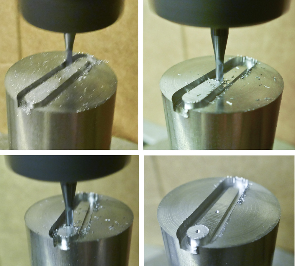 Bypass lever machining Bypass lever machining by ed cloutman, on Flickr 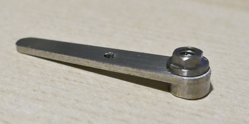 Lever and nut Lever and nut by ed cloutman, on Flickr |
|
|
|
Post by Roger on Jul 14, 2019 8:58:19 GMT
That's very neat, it's come out really well. I'm not sure why you don't drill the holes on the CNC mill. Perhaps this is because there's no separate quill and the drills would have to be set to a specific length? Is is possible on the Tormach to move from point to point and use a fine feed from the keyboard for doing those holes? If you could use up and down arrow keys to move the Z-axis really slowly that would be handy.
|
|
|
|
Post by David on Jul 14, 2019 10:48:16 GMT
You could do that. I never have though. I have the spotting drill permanently in its own chuck, and other drills set up on a per job basis.
I agree with Roger, it looks great and if that's a 2mm endmill, quite small!
|
|
|
|
Post by terrier060 on Jul 14, 2019 22:40:38 GMT
Hi Roger. The main reason I do not drill is that it requires more tool changes so I would prefer just spotting the drill centres and then drilling on my larger machine which has a manual quill. Like Dave I have a spotting drill permanently mounted as well as the 2mm end mill, both of which I use a lot. The tool heights of these are permanently in the machine which also speeds the setting up process. Also if I drilled through, it would mess up the next job as I part off the jobs as I finish them from round stock.
As you say Dave the lever is only an inch long.
|
|
|
|
Post by Roger on Jul 15, 2019 7:06:23 GMT
Hi Roger. The main reason I do not drill is that it requires more tool changes so I would prefer just spotting the drill centres and then drilling on my larger machine which has a manual quill. Like Dave I have a spotting drill permanently mounted as well as the 2mm end mill, both of which I use a lot. The tool heights of these are permanently in the machine which also speeds the setting up process. Also if I drilled through, it would mess up the next job as I part off the jobs as I finish them from round stock. As you say Dave the lever is only an inch long. Fair enough, I'm not sure I understand what you mean by messing up the next job? Even though it would require a tool change, I think I'd still do that because at that stage I would know that the drill is precisely above the hole. If you take it out, you have to set it up again or just hope it's vertical. Some jobs are tricky to hold once they've been cut out. I can see why you do it, but my instinct is always to do as many operations as possible while it's precisely set up. |
|
|
|
Post by terrier060 on Jul 15, 2019 9:00:04 GMT
Next are the racks for the reversing quadrant. I am making them in gauge plate. Ideally it would be nice to machine these complete with rack, but this would mean using a 1mm end mill. A lot of work in gauge plate for such a small cutter. As I do not have the luxury of a fourth axis, I must cut the rack on my vertical mill using my Myford indexing attachment. I can cut all four in one go which will make things easier using a 0.0625in end mill, but it does mean a separate setup. Perhaps it would be possible to do a separate contour stage in Fusion just to cut the rack. I will have a look into that.  Reversing quadrant racks Reversing quadrant racks by ed cloutman, on Flickr |
|
|
|
Post by Roger on Jul 15, 2019 9:04:59 GMT
Hi Ed,
I'd be inclined to rough out the slots with as big a cutter as you can get in there and then create a tool path for just those to finish them with a 1mm cutter. You don't need to go around the whole shape with the 1mm cutter, and it's only for cleaning up the last 50 microns and getting into the corners.
|
|
|
|
Post by terrier060 on Jul 15, 2019 15:12:27 GMT
Having discussed this with Roger this morning I have tried a method of cutting the rack in one go. I had to go back into the model sketch design and make 15 new bodies. These were extended by .02in as the new operation was pocket and the extra was necessary to ensure the 1mm cutter cleared the curve in the rack. So the upper sketch shows the tool path using the 2mm cutter, which cuts the outside profile, and then a 1mm cutter removes the slots as seen in the lower diagram. I am sure there must be a cleverer way of doing it, but this seems to work.  Rack pocket Rack pocket by ed cloutman, on Flickr |
|
|
|
Post by terrier060 on Jul 15, 2019 20:29:27 GMT
Here is the simulation of the rack being machined. It does not show the metal being removed from the pocket for some reason. You will have to click on the picture to make it play. The program I used is a free one and is great if you want to describe how to do something on the desktop. It is called OBS Studio. 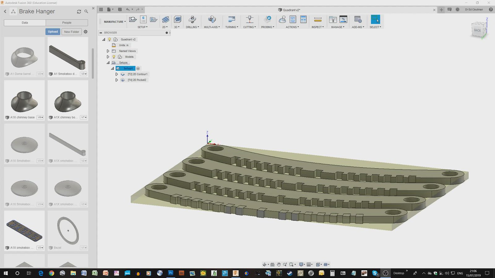 2019-07-15 21-06-56 2019-07-15 21-06-56 by ed cloutman, on Flickr |
|
|
|
Post by Roger on Jul 15, 2019 22:07:41 GMT
Hi Ed,
Is that being machined from sheet? If so, what stops them from detaching when they're complete?
|
|
|
|
Post by terrier060 on Jul 20, 2019 17:22:58 GMT
|
|
|
|
Post by Roger on Jul 20, 2019 18:27:53 GMT
That came out very nicely Ed. With regard to the feed and speed, those are around what I'd use but with less than half that depth of cut. I rarely take more than 1mm deep these days.
|
|
|
|
Post by terrier060 on Jul 20, 2019 20:36:49 GMT
I think you will find 1mm is 39thou. I am only taking 15thou cuts. I have been wondering if it would be better to take deeper cuts, as the bottom of my cutters seem to be wearing but not the sides. They may be rubbing rather than cutting?
On another subject, I have been looking at your chimney thread and you appear to have done it all in one operation using the 4th axis. Very neat. I wanted to ask you the best way for me to set up my chimney base so that when I turn it over it lines up perfectly to cut out the curve for the smokebox?
|
|
|
|
Post by Roger on Jul 20, 2019 22:10:52 GMT
I think you will find 1mm is 39thou. I am only taking 15thou cuts. I have been wondering if it would be better to take deeper cuts, as the bottom of my cutters seem to be wearing but not the sides. They may be rubbing rather than cutting? On another subject, I have been looking at your chimney thread and you appear to have done it all in one operation using the 4th axis. Very neat. I wanted to ask you the best way for me to set up my chimney base so that when I turn it over it lines up perfectly to cut out the curve for the smokebox? I must have calculated that wrong then, I got it as over 3mm deep. About 0.5mm on stainless is as far as I would go with a 4mmm cutter. If you do it on its side like I did, you must set up the centerline of the axis of rotation as close as possible to the X-axis. By that I mean that it's aligned with the X-axis and that it's exactly at Y zero. If the outside of the chuck is dead true when you click it while turning the rotary table then you can use the wobbler on both sides of that and halve the reading. I would never work off one side, it's not accurate enough. If you take the chuck jaws out and click the face of it to see if it's true. If it is, you can clock across it with a Y-axis movement and adjust the rotary table to get the face aligned with the Y-axis, and hence the X-axis would be aligned with the axis of rotation. Of course, you would set this first! Even if the chuck runs out a little, you can turn it to the point where the error is at 90 degrees to the axis you're clocking. That way it can strip be set correctly. The 3D model then just needs the zero of the CAM output in the Z-axis to be in the middle of the past and on the outside and. NB:- when setting up, make sure the stock stands out far enough to allow the tool holder to miss the chuck jaws! The zero in the X-axis can be the end of the stock. Basically ours pretty simple, you just have to make it so that when you turn the part over, it ends up exactly in a mirror position to where it started. NB:- When you create the CAM output, you will need to create a containment region that excludes the part of the job that's held in the chuck. I often extend the model to include an extra parallel part next to the chuck so I can control what the path looks like at that point. |
|
|
|
Post by Roger on Jul 20, 2019 22:12:42 GMT
If you're doing it in the vertical orientation, you need to have a flat you can use to clock across to get it aligned when you turn it over
|
|
|
|
Post by David on Jul 20, 2019 23:37:06 GMT
Hi Ed, the trunnion looks good!
You have 0.15" in your post which is why Roger didn't get the depth of cut.
I use full doc, and up to 0.04" woc if I can find a piece of stock that allows me to come in from the outside using adaptive clearing. In your case where this mightn't make sense I would use 0.02" - 0.04" doc unless I was using a rougher when I'd try maybe twice that.
I would try running the 4mm endmill at about 1600rpm simply because I watched a Stefan Gotteswinter video where he calculated the feed and speed for a 6mm HSS cutter and they were way above what I'd been using. The calculated feeds were still too fast for me, but the slightly higher rpms don't seem to be hurting.
There is a figure in the F360 dialogs that shows the load per tooth and I think if you know what that should be you can set the rpm or feed rate to what you're comfortable with then adjust the other until the tooth load is about right. I tried that with some drills recently and it worked well.
|
|
|
|
Post by Roger on Jul 21, 2019 7:00:48 GMT
You certainly can vary the parameters widely and use formulae, and some of the time that will work out just fine. The problem is that there's a huge variation in the difficulty of cutting different materials, and you're not always using a new razor sharp cutter. Some setups are much more rigid than others, so the amount of force you dare apply can be very different too. Then there's the ever present problem of chatter which is made worse by higher spindle speeds.
In my opinion it's a waste of time calculating these things once you get a feel for what it ought to look and sound like when it's happy. At best they are a starting point, but they can lead you into trouble if you stick closely to them in the mistaken belief that they must be nearly right. Sometimes you just have to go very slowly indeed, and with very light cuts to get the job done. Formulae are great for industrial mass production, but are of limited value in the home workshop in my opinion.
|
|
|
|
Post by terrier060 on Jul 21, 2019 14:20:02 GMT
Hi Ed, the trunnion looks good! You have 0.15" in your post which is why Roger didn't get the depth of cut. I use full doc, and up to 0.04" woc if I can find a piece of stock that allows me to come in from the outside using adaptive clearing. In your case where this mightn't make sense I would use 0.02" - 0.04" doc unless I was using a rougher when I'd try maybe twice that. I would try running the 4mm endmill at about 1600rpm simply because I watched a Stefan Gotteswinter video where he calculated the feed and speed for a 6mm HSS cutter and they were way above what I'd been using. The calculated feeds were still too fast for me, but the slightly higher rpms don't seem to be hurting. There is a figure in the F360 dialogs that shows the load per tooth and I think if you know what that should be you can set the rpm or feed rate to what you're comfortable with then adjust the other until the tooth load is about right. I tried that with some drills recently and it worked well. Well spotted David and my apologies to Roger! Probably late at night when I was writing it. That sounds useful info. I have also used full depth when I did the brake shoes, as I was fed up with the ends of the cutters losing their sharpness while the sides were virtually unused. Clearing can take a long time if there is a lot of metal to remove, so the present racks I am back to the 2mm cutter 1100rpm 0.015 DOC and 0.8in/min feed. Seems to be OK as gauge plate cuts with nice clean chips. I am cutting dry which is not the best but less smelly and messy as my workshop is next to the Kitchen!!! Also very easy to clean up after using the vacuum.  Machining the rack Machining the rack by ed cloutman, on Flickr |
|