|
|
Post by joanlluch on Feb 26, 2018 12:32:01 GMT
I originally designed my valve gear to have some "lead", i.e some pre admission of steam before the piston gets to the end of travel. At the time, this seemed adequate to me based on the reported benefits on full size locos. I was also told by a local that some lead would make the locomotive run smoothly. However, as I acquired more practical experience at running the locomotive on air, I am not so sure now that the above was a wise decision. To make things worse, lead in my locomotive is now more than originally designed because at some time I decided to replace the -commercial- valve rings by different ones based on ready availability and cost. The originals were like this:  And the current ones are like this: 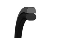 Compared with the original rings, the new ones are narrower towards the top, which reduces 'lap' and thus increase lead even further considering identical valve gear mechanism. I am now considering a redesign of the valve bobbin to reduce lead to zero or even provide some negative lead. I think that with no or even negative lead, the motion of the locomotive would be a lot better when the reverser is notched up. Any practical experiences on miniature locomotive behaviour, feeling etc based on the chosen lead would be appreciated. Joan |
|
|
|
Post by andyhigham on Feb 26, 2018 17:28:13 GMT
I would leave everything as it is until the loco has been tested on steam. Steam and air behave very differently
|
|
|
|
Post by chris vine on Feb 26, 2018 19:25:40 GMT
Hi Joan,
I agree with Andy. Air expands very little compared to steam. The engine may seem quite lumpy on air but will run very smoothly on steam as its pressure drops less as the volume expands.
A little bit of lead is a good thing, even in a model...
Chris.
|
|
jma1009
Elder Statesman

Posts: 5,901
|
Post by jma1009 on Feb 26, 2018 21:26:44 GMT
Hi Joan,
This is a subject that Don Ashton and I discussed at considerable length privately a few years ago.
My first loco to a Don Young design in 5"g (Railmotor) had large lead on the Walschaerts valve gear typical of Don Young. It ran extremely well on air initially just with one cylinder working. It has always run extremely well on air and steam.
There are 2 parts to "lead". Lead is the amount the valve is open dead centres. You then have to consider when the valve starts to open to steam as pre-admission. I prefer to think of this in angles of advance, and I think I received Don Ashton's approval for this way of thinking. Extensive experiments with a number of miniature locos indicated that the angle of advance should be between 4 and 6 degrees at full cut off. Don Ashton favours a smaller amount.
With Stephensons gear different considerations apply due to the variable lead.
Cheers,
Julian
|
|
|
|
Post by suctionhose on Feb 26, 2018 22:45:43 GMT
I have, in the past, followed Don Young with large lead, 20 or 30 thou from memory. Bollocks! Totally unnecessary in a model and not helpful in any way.
A dozen engines later, I would advocate zero lead although a crack of port for visual confirmation of 'open' on DC probably equates to a few thou lead.
the purpose of lead is to overcome inertia of steam at speed so cylinders fill to pressure at beginning of stroke.
This is real in full size because the volumes are larger (cubed), distances longer (×scale factor) and flow velocities higher.
Problems addressed by lead in fullsize do not exist in models. When the port cracks the pressure is there - instantly. Why have lead at all?
My best performing engine has almost zero lead and 75% full gear cutoff (I'd go the full 82% next time)
|
|
|
|
Post by joanlluch on Feb 26, 2018 23:24:00 GMT
Yes, I also considered leaving the loco as is and not changing anything until (or after) it's run on steam. However, I believe lead is still too much for the loco to work in a reasonable way. I also consider that a lot of people will be watching my first steaming at the club, so I rather have it as right as possible before the inevitable "experts" come in to give unsolicited late advice, if you understand what I mean.
The loco has a baker gear so it has constant lead, identical to a walschaerts from that point of view. I measure lead by setting the reverser just slightly to forward. I input air to one cylinder at a time and I watch air exiting the drain cocks. I have previously set the valve to the correct position by slowly turning the wheels by hand. The valve position can be easily adjusted from the outside. I set the valve at the position where the same pre-admission angle is found at both ends of the piston. That angle is determined by the start of air getting out through the open drain cocks. Such angle is currently 15 degrees at each end. In other words, the cylinder begins admitting air 15 degrees before the piston dead centre at each end. Before my decision of replacing the valve piston rings type, the pre-admission angle was about 10 degrees, still too much I guess. I could mount the old piston rings as they are not damaged, but I'd rather stick with the new ones for the reasons given in my previous post.
I suppose I am right at assuming that 15 degrees is beyond (worse) than anything considered even averagely correct, specially for the loco to be able to run at short cutoffs without getting stuck. I think I'm going to redesign the piston bobbin to correct that.
Joan
|
|
|
|
Post by fostergp6nhp on Feb 27, 2018 7:17:45 GMT
My experience with a 4” Foster single cylinder Traction engine and before anybody says they are totally different is right as you can see the effects easily.
The effect of having the recommended 1” of lead at the flywheel rim was that I could not get a slow tick over as below what ever the revs were it would just bounce back off the lead steam. The Foster is worse for this than other makes due to them having a thinner rim to the flywheel. Also it would not notch back but that was down to eccentrics having not enough throw. New eccentrics set to zero lead now let it tick over very slow and more throw giving full port opening let’s it notch back.
|
|
|
|
Post by builder01 on Feb 27, 2018 10:28:19 GMT
I have set my Super Simplex as close to zero lead as possible. The locomotive will start from a complete stop with the valves/wheels in any position. After the locomotive is moving, it can be notched up almost immediately and runs quite smoothly. If you attempt to start a locomotive from a complete stop, and the valves happen to be in a "pre-admission" position, you may have troubles getting started.
David
|
|
|
|
Post by ettingtonliam on Feb 27, 2018 16:51:49 GMT
Yes, I also considered leaving the loco as is and not changing anything until (or after) it's run on steam. However, I believe lead is still too much for the loco to work in a reasonable way. I also consider that a lot of people will be watching my first steaming at the club, so I rather have it as right as possible before the inevitable "experts" come in to give unsolicited late advice, if you understand what I mean. The loco has a baker gear so it has constant lead, identical to a walschaerts from that point of view. I measure lead by setting the reverser just slightly to forward. I input air to one cylinder at a time and I watch air exiting the drain cocks. I have previously set the valve to the correct position by slowly turning the wheels by hand. The valve position can be easily adjusted from the outside. I set the valve at the position where the same pre-admission angle is found at both ends of the piston. That angle is determined by the start of air getting out through the open drain cocks. Such angle is currently 15 degrees at each end. In other words, the cylinder begins admitting air 15 degrees before the piston dead centre at each end. Before my decision of replacing the valve piston rings type, the pre-admission angle was about 10 degrees, still too much I guess. I could mount the old piston rings as they are not damaged, but I'd rather stick with the new ones for the reasons given in my previous post. I suppose I am right at assuming that 15 degrees is beyond (worse) than anything considered even averagely correct, specially for the loco to be able to run at short cutoffs without getting stuck. I think I'm going to redesign the piston bobbin to correct that. Joan I'm no expert, but 15 degrees sounds far, far too much. Great Western locos were set with negative lead, but then they had Stephenson gear which increased the lead as they were notched up. Surely the decision whether to set lead based on the bobbin end or the ring edge depends on how good a fit the bobbins are? I'd be tempted to set the valves so that air is just starting to pass at dead centre. Didn't the late, much maligned in recent years, LBSC set his valves just open a crack at dead centre? Admittedly, most of his were slide valve, so easier to see valve/port relationship. |
|
|
|
Post by joanlluch on Feb 27, 2018 19:25:47 GMT
I'm no expert, but 15 degrees sounds far, far too much. Great Western locos were set with negative lead, but then they had Stephenson gear which increased the lead as they were notched up. Surely the decision whether to set lead based on the bobbin end or the ring edge depends on how good a fit the bobbins are? I'd be tempted to set the valves so that air is just starting to pass at dead centre. Didn't the late, much maligned in recent years, LBSC set his valves just open a crack at dead centre? Admittedly, most of his were slide valve, so easier to see valve/port relationship. Hi Richard, Yes, 15 degrees is far too much. There's a reason that explains why the loco ended with such an exaggerated value. It's related with your observation. The valve gear geometry was designed and fully simulated correctly to have ZERO lead. This was correctly done. I took the edge of the bobbin as a reference because I was advised to do so provided that the bobbin was supposed to be a good fit on the valve liner. When later on I took a decision on the kind of sealing rings, I removed the design requisite for a good fit for the bobbin. There's a diametral bobbin clearance of 0.6 mm between the bobbin and the liner. It's the rings what support the bobbin centred, not the bobbin, which removes any need for a close fit for the bobbin itself. At this stage, I should have adjusted the bobbin dimensions to account for the ring edge rather than the bobbin ends, but I didn't. I was conscious that this would add some lead, but I didn't carefully look at the actual figure at the time, and I thought that some lead was still ok. Then I made things worse by replacing the rings by a narrower type. The actual figure of lead came as a surprise because I didn't anticipate such a big amount. Of course, this could be all perfectly predicted and calculated, but it happened as described. I suppose we are humans. So if I am going to stick to this overall bobbin design and choice of rings, I must re-make the bobbin with proper dimensions accounting for the edges of the rings rather than the ends of the bobbin. Joan |
|
jma1009
Elder Statesman
Posts: 5,901
|
Post by jma1009 on Feb 27, 2018 20:08:39 GMT
Hi Joan,
There is a problem with your solution above.
The valve opening will be restricted by the bobbin and will not provide the large opening to steam that is so desirable for good valve events and performance.
This is nothing new. The Southern Railway 'Schools' class locos had exactly the same problems in the late 1930s as described by Harold Holcroft in 'Locomotive Adventure' Volume 2.
Cheers,
Julian
|
|
|
|
Post by chris vine on Feb 28, 2018 0:59:41 GMT
I think Julian is correct here.
If I have understood Joan correctly, the bobbin extends beyond the rings but has a diametral clearance of 0.6 mm IE a radial clearance of 0.3 mm. I think that this will certainly restrict the flow of steam if the rings are being regarded as the timing dimension.
Of course it depends on how long the bobbin is compared to the rings, but others in both full size and model size have taken care to reduce the diameter and thickness of this "land" beyond the rings. IE leaving the edges of the rings "exposed" as much as possible.
When testing on air, with a low pressure and at low or zero speed, the rings will certainly give the position of opening as there is very little flow and it will not be much restricted by the ends of the bobbin. However once the engine is running at speed and with a large flow of steam, I think the ends of the bobbins will have quite a restriction.
Chris.
|
|
|
|
Post by ettingtonliam on Feb 28, 2018 6:12:43 GMT
Harold Holcroft, in his book 'An outline of GW Locomotive Practice 1837 -1947' Fig 41 shows sections through 3 types of piston valves, plug, L ring and semi plug. The L ring and semi plug are shown with the ends of the valve body chamfered back level with the edge of the ring, which is, I suppose, a fairly obvious solution to this problem.
I do appreciate that this is knowledge from an old book, but there we are.
Julian, could you remind me what the issue and solution was with the 'Schools' valves? My copy of Cox is currently packed up awaiting a house move. PM me if you think this topic is too controversial.
|
|
|
|
Post by joanlluch on Feb 28, 2018 7:45:40 GMT
Hi Richard and Chris, Thank you for your input. This is my latest design for the valve:  PistonValveAssembly PistonValveAssembly by joan lluch, on Flickr The one currently installed in the loco is identical except for the total length of the bobbin and relative positions of the rings. The new design accounts for valve events referred to the edges of the rings as opposed to the currently installed one that accounts for the edges of the bobbin. The void spaces between bobbin elements are grooves for flat PTFE rings that are squeezed and packed in with some interference fit to create a safe seal between the parts. The position of the valve bobbin can be adjusted from the outside. I coloured the seals in red and blue just for illustration purposes. The new bobbin as drawn above has a radial clearance of exactly 0.35 mm with respect to the liner (or a difference in diameter of 0.7 mm). The one currently installed on the locomotive has a radial clearance of 0.25 mm (a difference of diameter of 0.5 mm). On both cases the width of the 'flanges' supporting the seals is 1 mm. On the admission side (inner admission) there's a rounded fillet before getting the max diameter of the bobbin. On air -and with the old bobbin with a radial clearance of 0.25 mm- the locomotive clearly behaves with valve events related to the edges of the rings, not the edges of the bobbin, which is why it has that much lead to begin with. At least this is what can be determined with tests performed at low pressure and limited flow of air. I recall having read in John Baguley web site that he used the edges of PTFE rings as references rather than the edges of the bobbin. But I do not remember what clearance or flange width he had for the bobbin. Thanks Joan |
|
|
|
Post by chris vine on Feb 28, 2018 10:47:03 GMT
Joan,
you are in danger of agreeing with Julian's helpful post.
Chris.
|
|
|
|
Post by ettingtonliam on Feb 28, 2018 11:08:18 GMT
It might not be a bad idea to radius the outer (exhaust side) land of the bobbin as well to get sharp exhaust timing. The GW valves that Holcroft shows had chamfers on the exhaust side as well, and were well known for sharp exhausts. I know that a number of things contributed to this, but the valve design was believed to be one of them.
|
|
|
|
Post by joanlluch on Feb 28, 2018 11:58:40 GMT
Joan, you are in danger of agreeing with Julian's helpful post. Chris. Indeed Chris, but he wasn't contributing with anything new or something that I didn't knew. He always does that. He often comes late to discussions started by me just to destroy them and add controversy. It's not a matter of agreeing or not with him. I do not regard his posts, full of references to people, past locomotives, and anecdotes as anything useful for me, specially because he just scratches the surface and is unable to get deeper into subjects. When asked for a clarification or more data, that he is supposed to have, he vanishes. I'm just feed up of him, honestly. This post is a live prove that he just caused a deviation to the subject of the thread. Private messages are meant to settle differences between members, not to worsen things. But he chose instead to post a public copy of a private message that I sent to him, instead of replying to me, which is childish. This all have a very long story, and I am not 'guilty' of anything else than building a non-prototypal, unconventional locomotive that he never appreciated or understood. That's the root of the problem. Of course, now he will report this (public) post and will make me appear as the "bad" guy on the movie. As said, I'm just feed up of him, honestly. Joan |
|
|
|
Post by chris vine on Feb 28, 2018 12:04:20 GMT
Hi Joan,
I know nothing of anything which as passed before, but in this case I think you are being unfair here.
Chris.
|
|
|
|
Post by joanlluch on Feb 28, 2018 12:06:23 GMT
It might not be a bad idea to radius the outer (exhaust side) land of the bobbin as well to get sharp exhaust timing. The GW valves that Holcroft shows had chamfers on the exhaust side as well, and were well known for sharp exhausts. I know that a number of things contributed to this, but the valve design was believed to be one of them. Hi Richard, I'm not sure if I understand your suggestion. The exhaust side already ends with a sharp (vertical) side, so steam has already free passage once it has reached the edge. However, adding some chamfer to the top of the 'flanges' -both on the admission and the exhaust sides- is possibly a good idea though. Joan |
|
|
|
Post by chris vine on Feb 28, 2018 12:29:19 GMT
Yes, the exhaust side should be done the same. To quote the great Churchward from the GWR in about 1920: "any fool can get steam into the cylinder, but it takes a clever man to get it back out again".
Chris.
|
|


