sis
Seasoned Member

Posts: 113
|
Post by sis on Aug 16, 2023 21:22:25 GMT
Hi,
I was discussing with and learning from a friend who is a member of the Burton upon trent club the topic of appropriate and or necessary deviations from scale when modeling from works drawings. Obviously, boiler and smokebox design is a clear example of necessary deviation and that is well documented. Roger's work on injectors etc is of course relevant as well. However what do the forum consider necessary compromises where deviation from scale is essential for a well functioning result?
My friend models in 3.5" gauge but personally Id be very interested in the view of the forum in other gauges.
For starters Axleboxes, hornblocks are over scale in the 7.25" designs I am somewhat familiar with, (GWR and BR standards), but how much is deemed necessary? For example Reeves Paddington, Mogul, King in 7.25" are all a good 1/4" over scale in width and not far off that in length of the frame cut away for the hornblocks, axleboxes and axles. Frame cut out for hornblocks might be in the range of 2" - 2-1/8" wide and approx 2-5/8" deep. On the smaller tank engines axles are in the order of Ø1" and in the large express perhaps Ø1.25". In the case of hornblocks is the limiting factor axle strength and the design is modified accordingly to suit? Or is it allowance for the inherently less smooth and straight tracks compared to standard gauge?
Perhaps Bob can comment on any compromises he made in his design for his 9F.
What other areas are necessary to deviate from scale? Are there any good references on the subject?
Thanks,
Steve
|
|
|
|
Post by chris vine on Aug 16, 2023 22:03:08 GMT
Hi Steve,
one thought is that all models which are smaller than full size are inherently stronger than the full size item. The reason is that the mass/weight of the parts/loco goes down with the cube of the scale, but the strength of the parts is mainly from the cross sectional area which only goes down with the square of the scale. So for a model 1/8 size, the ratio of areas to volume/mass/weight is 8 times. IE the model is more robust than full size.
For this reason, you should not need to increase the thickness of parts beyond scale, except where clumsy humans can exert more force on the model that the full size on small items like handles etc!!
I think the biggest area to concentrate on (apart from boilers) is the very un-scale track the engine will have to run on.
Chris.
|
|
|
|
Post by simon6200 on Aug 17, 2023 0:02:48 GMT
It all depends on the intended use of the loco when finished. If it’s going in a glass case it can be very close to scale. If it will be run every month doing heavy passenger hauling on an indifferent club track, then many compromises should be made. There are a couple of builds on this forum of super detailed scale models but I’m not sure the builders ever really intend to run them. They certainly would be very difficult to drive. I built my B1 (Springbok design) for public running days and made it easy to drive and maintain. It would not go round our tightest curves so I had to replace the bogie wheels with way under scale smaller wheels so they wouldn’t hit the cylinders. This doesn’t particularly bother me as the engine steams and runs very well.
|
|
|
|
Post by David on Aug 17, 2023 1:44:46 GMT
I find wheel standards to be the tricky bit. Down here we often use a scale of 1.125"/ft with 5" gauge, and we have our AALS wheel standards which use a B2B of 116mm and 16 to 20 mm wide wheels. When you draw this out you find running boards, splashers, the smokebox, and sandboxes are all affected and you must compromise as best you can within your limits of acceptable appearance.
|
|
|
|
Post by ianholder on Aug 17, 2023 14:10:14 GMT
As the designer of the 7 1/4 gauge GWR mogul referred to in SIS's post perhaps I may comment. In the first place it is not over scale in width as it is designed to a scale of 1.54" to the foot, the correct scale for 7 1/4 gauge and not 1.5". I think that most 7 1/4" miniature locos designed these days use this scale. I am not intimately acquainted with either the King or Paddington but imagine these would be to 1.54 scale.
I am not sure where SIS is coming from with his third paragraph, the hornblock cutouts on the mogul are 2 1/8 wide and 2 5/8 tall which scales to the works drawings I have in front of me and so is to scale and has not been modified.
Many of the designs in past years were notorious for being over wide, as clearances between crossheads and coupling rods were made far to great, Martin Evans was especially prone to doing this, and thus the cylinder centre lines were increased all leading to the locos being wider than necessary.
There are several moguls which are definitely not glass case and who's owners use them and they do not seem to have trouble with the average club track.
I am sure that when Bob comments you will find that has made no compromises with his 9F.
regards Ian
|
|
sis
Seasoned Member
Posts: 113
|
Post by sis on Aug 17, 2023 17:00:28 GMT
Hi Ian,
Thankyou for the corrections - ref the mogul at 1.54"/12" you are of course correct. With fresh eyes I checked again; the king is 1.5"/12", Paddington 1.5"/12".
Steve
|
|
dscott
Elder Statesman

Posts: 2,438
|
Post by dscott on Aug 19, 2023 22:44:28 GMT
I always go for as much weight as possible even with something as heavy as a Nigel Gresley where I have almost solid running boards.
Also a cannon type box round the rear axle from 3/8" plates to prevent ash getting into the bearings.
Footsteps can be thinned down on the visible edges as can backplates from 16 SWG and slimmed to scale.
David and Lily.
|
|
|
|
Post by pondok2 on Aug 23, 2023 20:11:25 GMT
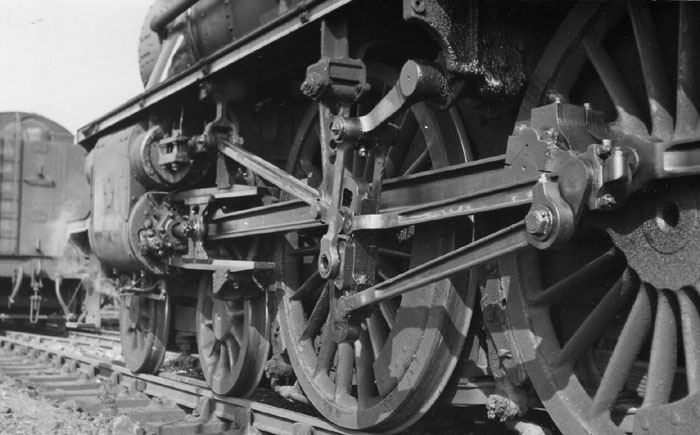
Hi Steve, A good question that got me thinking about my approach in all the locos I've designed and built. As already mentioned in the thread, it all depends on the intended result. I am happy to deviate from works drawings if I am asked to build something that looks and works right for regular running, but areas that are invisible on the track can be simplified for ease of assembly and maintenance and a finished loco in a reasonable time. As you say, boiler internals etc are obvious, but this also means the main frames and stretchers can be changed to suit available tools and workflow, for eg, I have done fully welded frames where the original would be bolted together, saving a lot of time. The time saved in these areas is then dedicated to prototypical accuracy of what is visible. Similarly with fixings, most internal structures can use stainless metric fixings, saving the more scale appearance BA fixings for conspicuous parts. An example below, the frames have completely un-prototypical welded half channel horn stretchers (I'll explain if you like), bolted to the frames with M5 stainless hex, but as much external detail as possible in the time - 4 years construction.  |
|
44767
Statesman

Posts: 529
|
Post by 44767 on Aug 25, 2023 12:11:02 GMT
Hi Steve, one thought is that all models which are smaller than full size are inherently stronger than the full size item. The reason is that the mass/weight of the parts/loco goes down with the cube of the scale, but the strength of the parts is mainly from the cross sectional area which only goes down with the square of the scale. So for a model 1/8 size, the ratio of areas to volume/mass/weight is 8 times. IE the model is more robust than full size. For this reason, you should not need to increase the thickness of parts beyond scale, except where clumsy humans can exert more force on the model that the full size on small items like handles etc!! I think the biggest area to concentrate on (apart from boilers) is the very un-scale track the engine will have to run on. Chris. With respect, Chris, the stiffness of a part is not the ratio of volume to cross sectional area but the ratio of cross sectional area to length. Since, when a model is scaled, the cross sectional area comes down by the square of the scale and the length comes down by the scale, the part becomes less stiff as the scale decreases. Take it to an extreme is what I visualise this sort of thing; if a part is scales down to a point where the thickness is waffer thin, how can it be more stiff than the full-size part? |
|
|
|
Post by 92220 on Aug 25, 2023 15:06:38 GMT
I hadn't thought about it along those lines (no pun intended!!) but the boiler clothing sheets on a 9F are 16swg, and when scaled down for a 5"g loco, the clothing would be 0.0055" thick. very flimsy!! On my 9F I am making the clothing sheets from 10 and 12 thou sheets, but this is all supported with an inner shell of 0.5mm nickel silver sheet to help stop it getting bent by very light loadings.
Bob.
|
|
|
|
Post by ettingtonliam on Aug 25, 2023 15:38:58 GMT
Sheet metalwork (cabs, tanks, running plates) in full size would be typically 3/8" thick, 0.375". In 5" gauge, thats 1"/foot, so scale thickness would be about 30 thou, far too thin even in steel instead of the normal brass. Frame plates often about 1 1/4" thick, would scale at 0.100", which is on the thin side compared to the usual 1/8" or 5/32".
|
|
|
|
Post by ianholder on Aug 25, 2023 17:21:37 GMT
Plate work in full size is 1/8" or perhaps 3/16" at the most never as thick as 3/8".
|
|
|
|
Post by ettingtonliam on Aug 25, 2023 21:16:00 GMT
Are you sure about that? The running plates were quite substantial because in pre BR days anyway, they acted as horizontal stiffeners for the frames. Tanks were only 1/8" thick?
Anyway, if what you say is true, it makes my point even more valid, 1/8" platework scaled down for 5" gauge would be 10 thou thick.
|
|
baldric
E-xcellent poster
Posts: 208
|
Post by baldric on Aug 26, 2023 9:46:30 GMT
Many GWR tanks are 3/16" plate, I can't remember if the running plate is 3/16" or 1/4" but certainly not 3/8". Either way, it wouldn't scale well.
Baldric.
|
|
|
|
Post by nblackburn on Aug 31, 2023 7:47:50 GMT
I am starting to build, scaled from GA drawings, a North British D30 in 5". No problems so far but I have been going through Don Ashton's Valve gear book which has me confused.
My question is: Can you scale the Valve gear (stephensons, loco links with rocker levers directly from the GA drawing.
Norman
|
|
mbrown
Elder Statesman
Posts: 1,719
|
Post by mbrown on Aug 31, 2023 15:55:14 GMT
You can usually scale the valve gear directly - provided the ports, lap, lead etc are also exactly to scale.
My approach has been to design the valve gear, using the fixed points like the expansion link pivot taken from the prototype GA, and then use a valve gear design programme. Interestingly, on the Burma Mines loco, the dimensions of each part were astonishingly close to scale. The cylinders used Martin Evans's Jubilee castings and I had adopted his dimensions for ports and valve. When I checked back, these coincided almost exactly with scale size too, so no wonder the valve gear ended up similar.
On 99 3462, some dimensions will have to be unprototypical as the original seems to have had a surprisingly small lap and lead component and I wanted to stay closer to the usual model parameters.
Hope that is helpful
Malcolm
|
|
|
|
Post by nblackburn on Sept 1, 2023 7:07:00 GMT
Malcolm
Thanks for thoughts. I think that I will be using slide valves instead of piston so as you say check the lap/lead and port sizes.
Norman
|
|
|
|
Post by suctionhose on Sept 1, 2023 7:48:41 GMT
Actually, to change from piston on prototype to slide on model requires several alterations to Stephenson's including eccentric orientation, suspension pin offset from link slot and, ideally a change of link type.
So to your question - can I scale the full-size drawing - yes, but only if you don't change anything! Stephenson's, in particular, has many hidden dependencies that require a deeper understanding if you want to alter the fundamentals.
|
|
oldnorton
Statesman
5" gauge LMS enthusiast
Posts: 693
|
Post by oldnorton on Sept 1, 2023 8:49:22 GMT
I guess that if anyone wanted to build a 'true-scale' reduction 5 inch gauge model it would have to be kept in a glass case and be very tricky to handle, touch and lift. One tenth inch frame plates are not a problem but 0.012" thick running plates and 0.006" cleading would not tolerate much finger pressure. I dread to think of the size of the valve piston rings!
However, pick a full size loco up by its buffer stocks and everything would bend, but you could probably do so with that 'true-scale' model. We can all do that with our models with ease because everything at the front is much thicker.
The issue of forces and strengths as size changes intrigues me and I don't know the scientific answers, but surely a proper engineer or physicist knows the maths? I respect Chris' (engineer) view on the thought that smaller versions of a thing in metal can withstand proportionally higher forces. What comes to mind is the construction of bridges from steel and maximum length of spans. If you designed a model bridge in steel it might support 1kg, but as it gets bigger I intuitively feel it is not going to support the cube of its linear growth. Eventually, it comes to a point where it is so large that it cannot support itself as the material mass in the beams is greater than its strength.
For further example: pick up that 0.012" thick by 12" long scale running plate with a pair of pliers in the middle and it will droop, but try and do the same with the 0.125" by 10 foot long full size (using a crane!) and I can see the ends not wanting to come off the ground.
My view on using works drawings is that, of course, you take the length, width and height of the positions (dimensions) of the original to make the model. But the thickness of materials, and size of fittings, must be re-set to make construction and real use a viable process. This will inevitably require the adjustment of some of those dimensions to accommodate the re-sized components. A job that Greenly, Perrier, Young, Breeze, Evans and many others have done with struggles and skill.
Norm
|
|