sis
Seasoned Member

Posts: 113
|
Post by sis on Mar 24, 2024 15:22:20 GMT
Hi ,
EDIT - this should have been in the CAD sub forum. I dont seem to see where I can do that.
I have some scans from the NRM. I am using these as a canvas in Fusion 360.
The trouble is that fusion allows me to calibrate the scan by picking 2 points and sizing the distance between them. In practice this means picking one dimension only. I have found that the scans are not consistent - I would like to resize the scans differently in each dimension.
Does anyone know of any software that will allow resizing differently in X and Y?
Thanks,
Steve
|
|
Neale
Part of the e-furniture
 5" Black 5 just started
Posts: 279 
|
Post by Neale on Mar 24, 2024 16:04:41 GMT
What format are the scans in? If it's a bit image format (jpg, bmp, etc) then a fair number of graphics programmes would do the job. My choice would be GIMP - free, open-source, fairly powerful - which I think will allow separate scaling in X and Y.
|
|
sis
Seasoned Member
Posts: 113
|
Post by sis on Mar 24, 2024 21:09:55 GMT
Hi Neale,
TIFF - but I can save them in JPEG or PNG as needed. I was perhaps not clear - in the sense I want to scale the images to a dimension within the image itself. and do that separately for X and Y. I know there are many packages in which I can scale in X and Y but only in pixel count. Fusion lets me scale one time only with the canvas calibrate function. I think the NRM scanners are bad - the images come out shrunk in Y compared to X.
Thanks,
Steve
|
|
peteh
Statesman
Still making mistakes!
Posts: 760
|
Post by peteh on Mar 25, 2024 0:50:07 GMT
If you have access to Autocad (or maybe a clone) you can make the image into a block. The block can then be independantly scaled in X and y. Exploding the block brings back an image at the correct scale.
Not sure what would happen if you tried to then export the image though.
Used this trick frequently in the town planning game when I was in that.
|
|
jasonb
Elder Statesman

Posts: 1,209
|
Post by jasonb on Mar 25, 2024 7:13:11 GMT
Alibre allows you to resize imported "trace" images in both X and Y as well as rotate them and move the whole image to put the drawing axis where you wnat it, though I don't think it will output the image for use in another CAD program. I use it a lot with old photos and engravings when designing my own engines. The way I do it is import the image at whatever size it is then draw a line along a known dimension or say across the diameter of a flywheel and note it's length. Lets say the line is 17.5" across a flywheel and I want a 7" one on the model. All I do is go back to the import window and make the image 40% (7/17.5) of its imported size, same for something at right angles to the first line. No need for pixels etc This is one I scaled to suit the flywheel size, no dimensions on the drawing but once scaled you can just draw lines and get their length 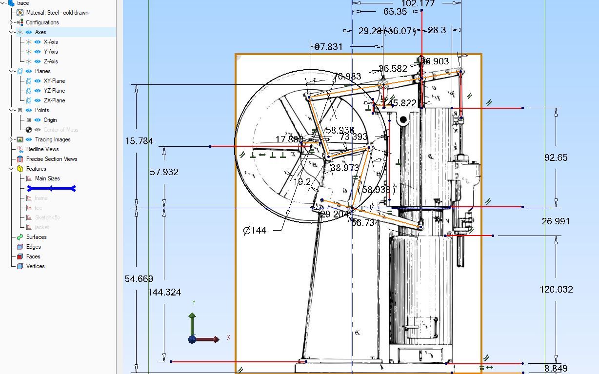 Build up the whole model over the image 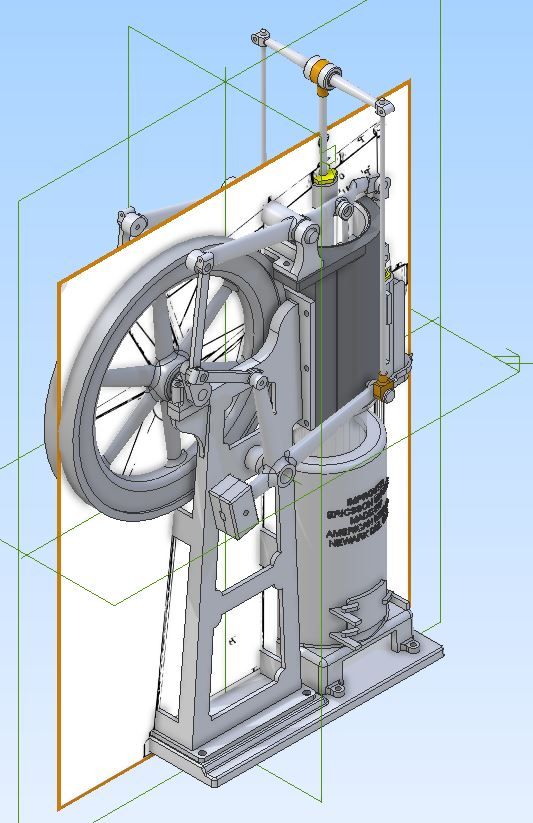 This one shows a photo that has been scaled up, rotated and shifted so the axis goes throught the crankshaft 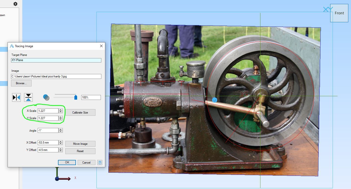 |
|
jasonb
Elder Statesman
Posts: 1,209
|
Post by jasonb on Mar 25, 2024 7:44:37 GMT
I just looked at F360 and you can do it in exactly the same way a sI described. You just need to enter numbers in "Scale X" and "Scale Y" Import your image as a "canvas" Draw two lines along some know lengths and give them whatever dimension comes up approx 9cm in this case 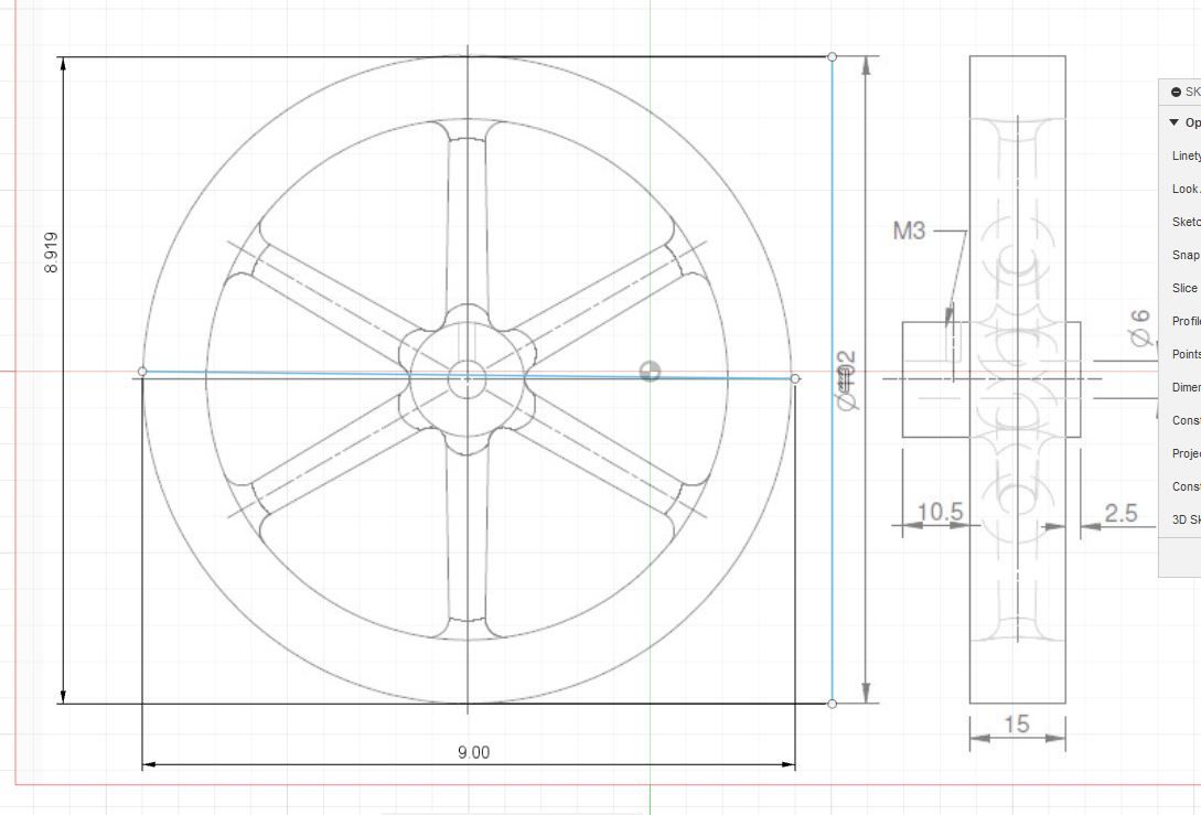 Then go back to the canvas and edit the "Scale X and Y" to suit in this case I have entered 10.2 / 9 as I want to make the part the full size of 102mm dia. You can see that as I have only enlarged one axis at this stage the flywheel has been stretched in one direction only. 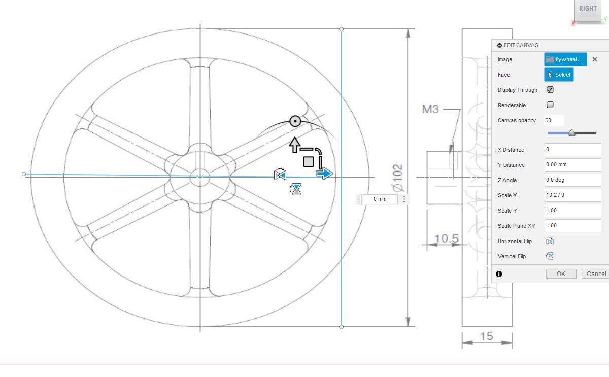 Any subsequent lines etc drawn on the drawing between two points will be the length you actually want. may take a couple of tweaks of the scale factor, as you can see I need to adjust it slightly. 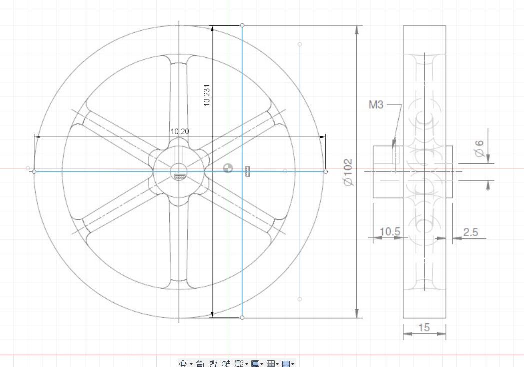 |
|
johan
Active Member

Posts: 29
|
Post by johan on Mar 25, 2024 19:27:49 GMT
Remember that plans are never meant to be measured on! Only gives dimensions are to be counted on.
|
|
jasonb
Elder Statesman
Posts: 1,209
|
Post by jasonb on Mar 25, 2024 20:13:01 GMT
However there are times when you have to ignore that "rule" if you want to get things done.. For example castings seldom have the dimensions shown to the cast faces only the surfaces and features to be machined are dimensioned. So if you want to replicate a casting be it full size or model that is no longer available you will have to take your sizes off the drawing if one exists. Or in the instance of the hot air engine I showed above working from a patent drawing there are no sizes given so all has to be proportioned to the known 8" bore. Same if all you have to go on is a photo to work from. Typical example here of some drawings I was working to where the designer was no longer able to supply castings. I bought the drawings which just show the machined bits dimensioned 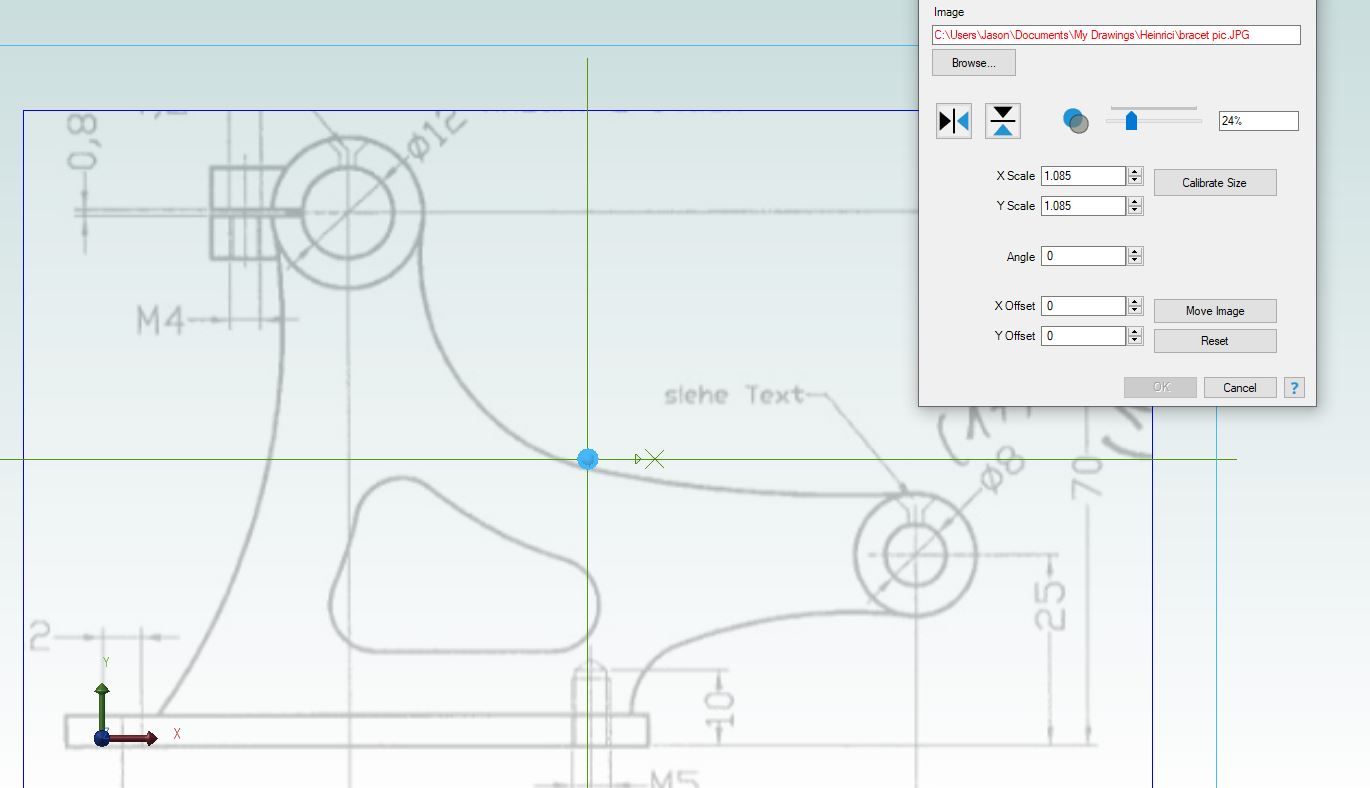 Used that to work out the rest of the shape 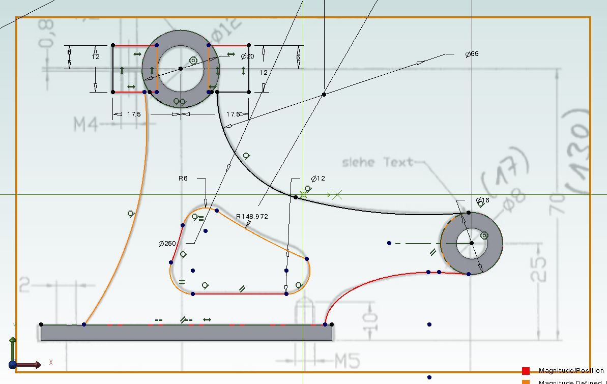 So I had a complete 3D model of that and the rest of the castings were treated the same. Also added in items he had left off after referring to photos of original engines. 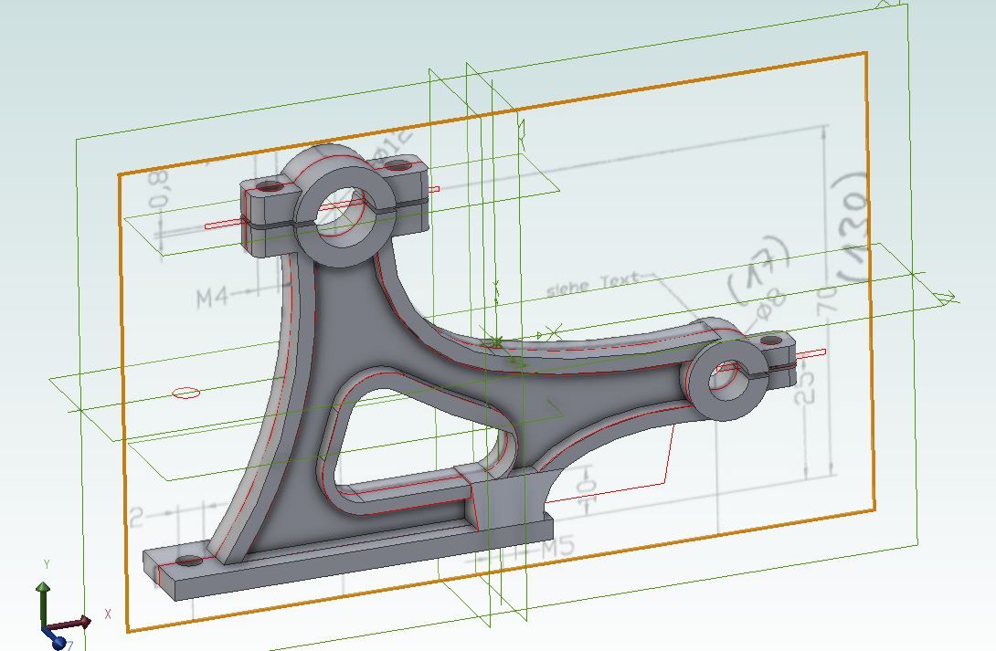 If I had stuck to not taking sizes off a drawing I would not have this engine made. Oh and not all new models need bright paintwork. 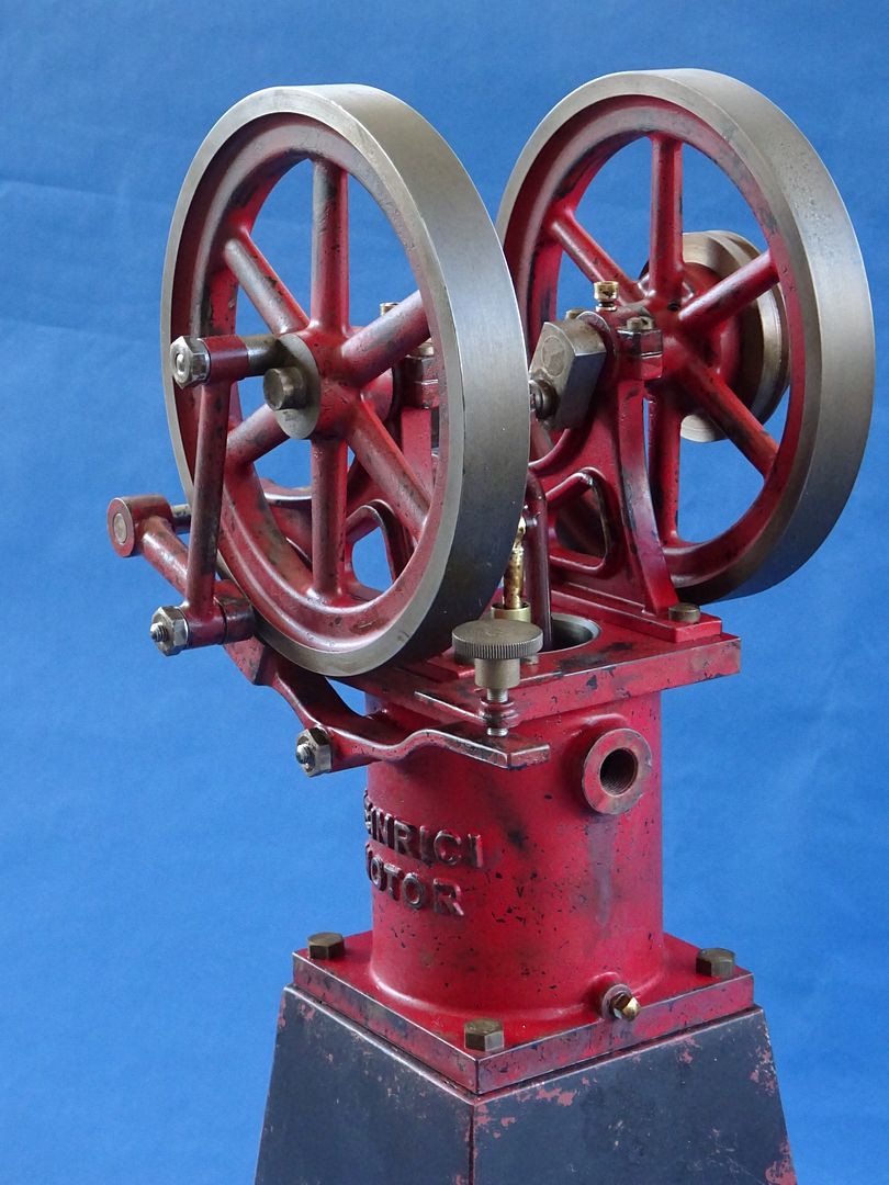 |
|
|
|
Post by ettingtonliam on Mar 26, 2024 9:29:23 GMT
Just curious, but was the patternmaker given a separate drawing with all the dimensions of ribs, bosses etc on it plus machining allowance, or was he just given the drawing of the finished component, and left to his own devices to make a suitable pattern, including cores and coreboxes?
|
|
johan
Active Member
Posts: 29
|
Post by johan on Mar 27, 2024 8:52:53 GMT
Just curious, but was the patternmaker given a separate drawing with all the dimensions of ribs, bosses etc on it plus machining allowance, or was he just given the drawing of the finished component, and left to his own devices to make a suitable pattern, including cores and coreboxes? Pretty sure he was given the drawings of the finished components together with info on machining allowance needed where. But dividing, cores, shrinkage would be his knowledge and part of the job. When I made drawings for parts to be made (ok, plastic parts) I delivered a drawing of the finished part, indicating tolerances, which surfaces needed to be free of parting lines and what finish they should have and which dimensions were strict and those that could change due to release angles. And of course what material and colour(s) would be used. That was cleared with the mould designer and then it was his job. |
|
sis
Seasoned Member
Posts: 113
|
Post by sis on Mar 29, 2024 8:09:37 GMT
Thanks all
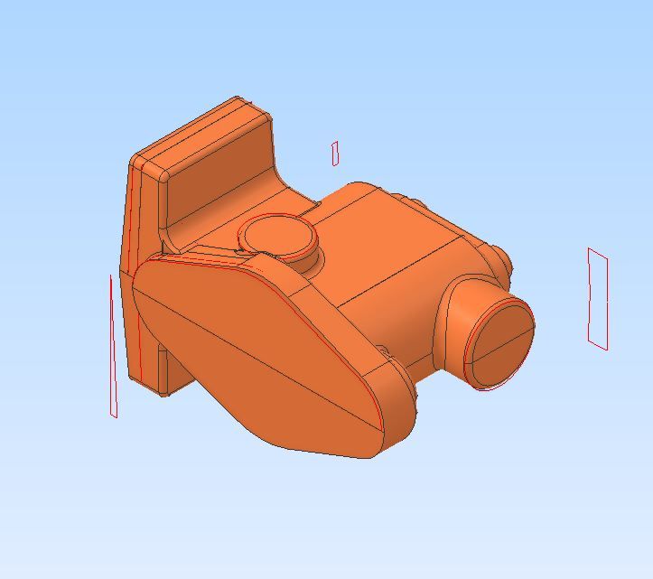
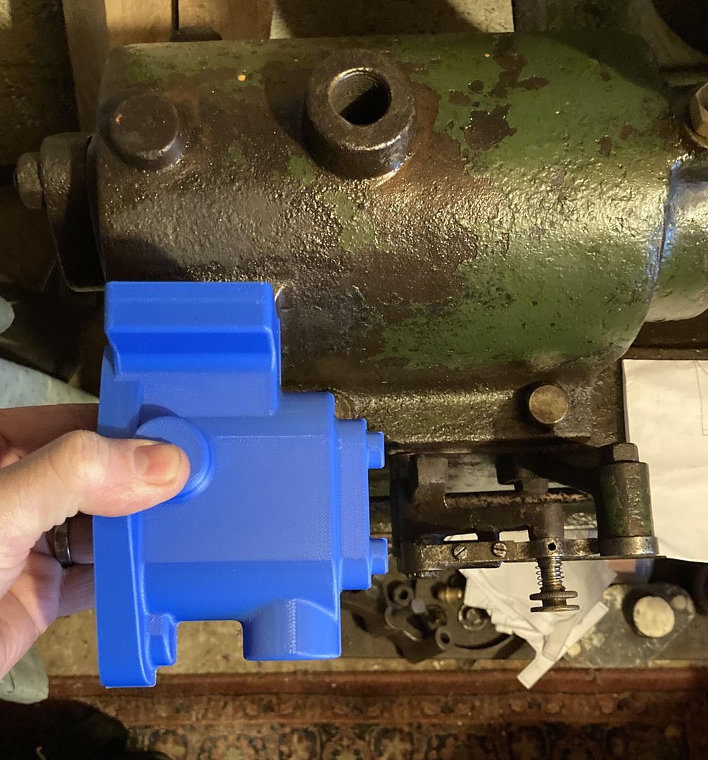
Some really good information here. And yes i am drawing up castings and many of the dimensions to get the look correct are missing so “tracing” a canvas is useful.
I’ll hopefully have chance to test over the weekend.
Thanks
Steve
|
|
jasonb
Elder Statesman
Posts: 1,209
|
Post by jasonb on Mar 29, 2024 13:26:07 GMT
I don't know what units you like to work on but having done the CAD work to reverse engineer castings for people it is worth making your "trace" full size and then the common fractional imperial sizes drop right in. Much harder if you are given or working in metric from old castings or have scaled the part down by an odd factor.
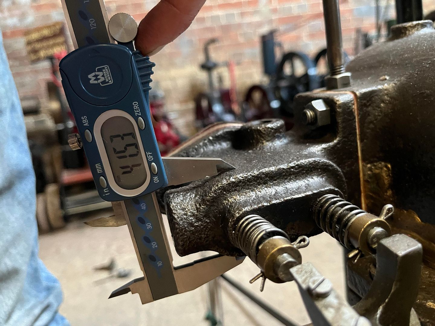
That 41.53mm caliper dimension you were sent makes a lot more sense when converted to imperial as the designed size then looks like 1 5/8" allowing a bit for the irregularities of a casting.
|
|
johan
Active Member
Posts: 29
|
Post by johan on Mar 29, 2024 20:27:06 GMT
I don't know what units you like to work on but having done the CAD work to reverse engineer castings for people it is worth making your "trace" full size and then the common fractional imperial sizes drop right in. Much harder if you are given or working in metric from old castings or have scaled the part down by an odd factor. That 41.53mm caliper dimension you were sent makes a lot more sense when converted to imperial as the designed size then looks like 1 5/8" allowing a bit for the irregularities of a casting. Oh, you mean 1.625"? Might be, might not be. And 41.53mm is just a measurement error of 41.5mm which is quite simple isn't it? You're working from a scan of a print from a copy of a drawing. If you're lucky... And then you're putting in lines and measurements where you think the original line was. Honestly, I would not even bet on that 41.53mm not being 40mm originally. |
|
jasonb
Elder Statesman
Posts: 1,209
|
Post by jasonb on Mar 30, 2024 7:57:32 GMT
|
|
sis
Seasoned Member
Posts: 113
|
Post by sis on Mar 30, 2024 18:05:41 GMT
Hi
For pretty much everything including components that will be cast I draw to works drawings in full size.
Then i scale the finished items - im working in 7.25” so 1.54” scale factor which ends up in decimal dimensions which thanks to CAD and dro is not so bad.
|
|