ace
Statesman

Posts: 528
|
Post by ace on Jun 11, 2008 23:04:41 GMT
Can anyone tell what type of stater switch I need to replace the one on my Myford ML7. The starter switch (a MEM ) has finely given up and I am unsure of what type to buy there are so many different types on the market. As you may guess I'm no electrician and do not wish to buy the wrong type. The motor is a Cub and has the following marked on it -
HP - .33
Volt - 220/230
Phase - 1
Rating - Cont
Speed - 1420
then there is a small wavy line and 50 stamped next to it.
The motor starter switch is not listed in the parts book and from the look of it about 40 year old.
|
|
|
|
Post by baggo on Jun 11, 2008 23:25:39 GMT
Hi Ace,
I think the 'standard' switch supplied for the Myford used to be the Dewhurst which gives off, forward, and reverse. I don't know if these are still available new but sometimes appear on Ebay although they often go for silly money.
You basically need any switch which will supply live and neutral to the main 'run' winding of the motor and can reverse the supply to the start winding to give forward and reverse (assuming you have a reversible motor)
I do have a s/h Dewhurst sitting in a drawer since fitting my Myford with a 3 phase motor and variable speed inverter (best mod I ever did!) so if all else fails I may be able to help you out.
John
|
|
|
|
Post by dickdastardly40 on Jun 12, 2008 6:48:49 GMT
Ace,
Sorry to hear the starter has given up the ghost finally. Nice to see you post again.
How does your lathe reverse? Do you have 2 switches, an on/off which has gone wrong and a reverse.
It sounds (to me at least) like the switch that has failed is a direct on line starter/contactor type. You will need a single phase version; a quick look on ebay finds none unfortunately.
If you could put a pic up we can confirm what it is you're looking for.
Al
|
|
jackrae
Elder Statesman

Posts: 1,333
|
Post by jackrae on Jun 12, 2008 10:06:46 GMT
Ace,
What makes you certain that it is your starter that has failed.
"a small wavy line with 50 next to it" suggest your electrical knowledge is a bit on the short side and your diagnosis may be incorrect.
If it is the starter (is it really a starter ?) then it may well be repairable.
An alternative to an expensive 1-phase starter is a 3-phase starter providing you use a 240volt coil and loop the live line through all three heater coils.
I'd suggest you seek the guidance and assistance of someone with the relevant knowledge before you go too much further - volts don't take prisoners!
regards
jack
|
|
ace
Statesman
Posts: 528
|
Post by ace on Jun 12, 2008 17:03:20 GMT
Many thank guys for the quick replies.
I will post a picture of the suspect switch later today. Yes Jack your right my knowledge of the killer volts is limited but having posted this subject before and managed to bring back to life the switch with help from fellow engineers I'm sure that it has died again.
Al, You posted me some tips on the starter a while back and that seemed to work then but now it just makes a clicking sound and does not start the motor.
John, The forward / reverse switch is fine.
Unfortunately I have been having problems with my computer for the past few months and have only just managed to access the net (Virgin Media rubbish) so have missed out on posting any messages and reading other topics . Good to be back though this is a great site with many interesting characters and topics, for me a good source of info.
|
|
ace
Statesman
Posts: 528
|
Post by ace on Jun 12, 2008 17:26:36 GMT
Hi guys Photos of the offending part. 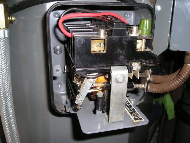 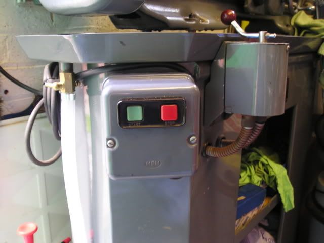 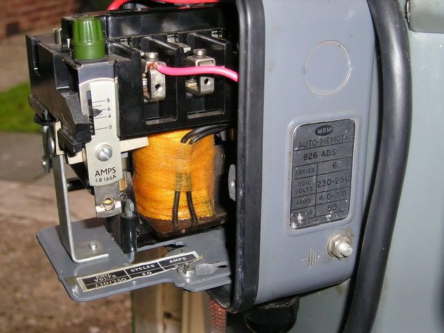 |
|
jackrae
Elder Statesman
Posts: 1,333
|
Post by jackrae on Jun 12, 2008 19:20:28 GMT
Ace
From your photos I see that your thermal overload is set at around 6 amps. For a 1/3HP motor somewhere around 1.5 amps would be nearer the mark.
However your starter also appears to be a 3-phase device with a 230volt coil fitted.
It seems that you have both live and neutral routed through the contactor.
Because the contactor is a 3-phase device the overload will be looking at "lost-phase" imbalance and will expect the same current to be flowing through all three legs. I would suggest that the setting of 6 amps on the overload is how you've overcome the lost phase tripping since the overload will see no current in phase 2 and so will be endeavouring to trip due to the imbalanced currents. However the overload now fails to provide adequate protection to your motor.
I would suggest that you re-wire your live circuit such that the live output of phase 1 contact is wired back as an input to the phase 2contact. The output of phase 2 is then wired to wherever the live is currently wired to (reverser switch ?)
This will then permit you to correctly set your overload to suit the motor current. In effect phase 1 and phase 2 overloads see the live current and phase 3 sees the neutral current (flowing in the opposite direction but this is irrelevant for a thermal overload).
If you contactor is clicking, what happens when you hold in the start button - does it still click or does the motor run (or smoke). If so then I'd suggest that the self-hold auxilliary contact is failing to make the circuit. Is there a time delay (1 second or so) between pressing the start button before the click-if so then it's possible the overload is tripping due to a motor fault
Some observations as to what is actually happening would be a great help in permitting us to suggest possible faults
regards Jack
|
|
|
|
Post by falmerbank on Jun 12, 2008 20:42:00 GMT
Looks like the standard mem NVR motor starter box and thurmal cut out. Jack is spot on about the lost phase and it is normalty written inside the lid of the box. The normal failer mode of these starter units is the contacts themselves check with a multimeter or bulb and battery to see if each contact conducts. ( WITH OUT THE MAINS PLUGED IN !!!!!) a quick clean with a diamond file and wiping with meths sorts them out. if that fails it could be the coil, it should be about 1000 ohms. If it does not conduct or is less than 100 ohms its time to buy a new one ..Axminster power tools doone simular on part no 340192-22
have fun keep steaming Falmer Bank
|
|
ace
Statesman
Posts: 528
|
Post by ace on Jun 12, 2008 21:59:57 GMT
Hi Jack Firstly, the bloody thing has decided to work tonight  although it did buzz loudly. When I pressed the stop button and the start button again it was quite. I have stopped and started it several times and it buzzed on 5 out of 7 tries. When its running the motor and lathe run great apart from the buzzing sound and like I said sometimes the noise is louder. All the manufacturers info is on the inside as Falmer pointed out. I will have a look again at the switch tomorrow and see if I can see whats goin on inside, and then let you know. Many thanks Steve |
|
|
|
Post by baggo on Jun 12, 2008 23:26:39 GMT
Might have one of those or something very similar up in the loft. Will have a look tomorrow.
John
|
|
|
|
Post by circlip on Jun 13, 2008 9:27:24 GMT
What a wonderful dissertation on multi phase electrics, thanks for that Jack.
OK Ace for the practical answer to if your starter is wired correctly, Tubal Cains "Model engineers handbook" not only gives invaluable workshop info, but also a diagram of how to wire a three phase starter for single phase operation for thickies like thee and me.
Not sure we should be playing with electrikery like this anymore, Sparkies have to have 25 Feet of certs with an advanced course on screwdriver twiddling.
Bemused Regards Ian.
|
|
|
|
Post by pcplod on Jun 13, 2008 10:25:14 GMT
It all looks so incredibly clean - where am I going wrong - something to do with actually machining lovely dirty stuff like cast iron wheels  Plod |
|
ace
Statesman
Posts: 528
|
Post by ace on Jun 13, 2008 18:47:31 GMT
Baggo
if you have got one I would be happy buy it and pay postage, I would really like to keep the character of the beloved lathe, its my pride an joy. The new switches are OK but it wont look right.
Circlip
Yep Jack's version is brill, but why have a dog and bark yourself... I'll give the electrical chaps at work a defect note for this and an offer of a drink or two and see who comes round to my house to do it. ;D
Plod
Yes it clean..... but it don't work so what else do I do in my spare time ;D ;D ;D
|
|
|
|
Post by baggo on Jun 13, 2008 20:42:15 GMT
Hi Steve, Just managed to find it amongst the other junk (treasure) but unfortunately it's a 380/440 volts at 2 to 4 amp version. Identical in all other respects though. Has yours still got the wiring diagram in the lid? For single phase use the supply should be on L1 and L3 with the motor connected to A and C. It doesn't say that L2 has to be connected and IMHO it should work without that as the operating coil is only connected across L1 and L3, even with a three phase supply. You can connect in the third contactor by doing as Jack suggests. In that case connect the supply to L1 and L3 as before, connect C to L2, and connect the motor to A and B. Don't play with it though if you're not confident about doing it  As mentioned by Falmerbank, it could just be dirty contacts causing the problem John |
|
paul
Member

Posts: 8
|
Post by paul on Jun 13, 2008 22:27:34 GMT
It all looks so incredibly clean - where am I going wrong - something to do with actually machining lovely dirty stuff like cast iron wheels LOL just what I thought! Nice to hear your still with us Ace! |
|
ace
Statesman
Posts: 528
|
Post by ace on Jun 13, 2008 22:33:00 GMT
Many thanks for looking John, bet you saw things up there you had forgotten about.  As posted before I will ask one of our sparkies on Monday to have a look at it and may be if it has had it he can get me a replacement switch. I guess I will have to just spend sometime cleaning up the w/shop and doing those must do jobs instead ;D ;D Let you know what was wrong and what went on soon. cheers Steve |
|
|
|
Post by houstonceng on Jun 13, 2008 22:42:00 GMT
Hi Jack Firstly, the bloody thing has decided to work tonight although it did buzz loudly. When I pressed the stop button and the start button again it was quite. I have stopped and started it several times and it buzzed on 5 out of 7 tries. When its running the motor and lathe run great apart from the buzzing sound and like I said sometimes the noise is louder. All the manufacturers info is on the inside as Falmer pointed out. I will have a look again at the switch tomorrow and see if I can see whats goin on inside, and then let you know. Many thanks Steve A common problem on these is that, sometimes, the moving part of the electro-magnetic mechanism fails to seat properly onto the fixed part. These are often in the form of laminations like a transformer and can be like E and I where the coils ate on the "E" section and the "I" section is attracted to it. Dirt or rust on the ends of the E holds the I with a slight air-gap = buzzing. De-energised and then re-energised the contact is better and the air-gap is less = no-buzzing. You'll often get a slight 50Hz "hum" - made louder by the NVR being mounted on the lathe cabinet which acts as a sound-box. |
|
ace
Statesman
Posts: 528
|
Post by ace on Jun 13, 2008 23:00:19 GMT
Hi Paul
Its good to be back, have missed the site.
I have over the past few days spent more time cleaning my machines than using them and I only unwrapped the lathe from its winter jacket last week. Hopefully I can get down to some model making next week.
Steve
|
|


 although it did buzz loudly. When I pressed the stop button and the start button again it was quite. I have stopped and started it several times and it buzzed on 5 out of 7 tries. When its running the motor and lathe run great apart from the buzzing sound and like I said sometimes the noise is louder. All the manufacturers info is on the inside as Falmer pointed out. I will have a look again at the switch tomorrow and see if I can see whats goin on inside, and then let you know.


