|
|
Post by Roger on May 21, 2019 16:58:04 GMT
Hi Roger, I love your level indicator. Very cute. My only thought is that your indicator pointer looks like a small handle on a valve. I am pretty sure that someone (in ignorance) will try to turn it!! Chris. Hi Chris, Glad you like it, but Andy has it spot on... you can turn it but it just feels like it's on a spring, you won't break it like that. |
|
|
|
Post by Roger on May 21, 2019 17:23:22 GMT
Before I start soldering all of this together, I needed to check that the balance pipe position is correct and that it all fits when the fixing bolts are in place.  20190521_171931 20190521_171931 by Anne Froud, on Flickr All looks fine, so that's good news. It's clear that you won't be able to take the balance pipe off without removing at least one of the tanks first. That's not really a problem, it's likely the tanks that are going to need taking off anyway rather than that.  20190521_172004 20190521_172004 by Anne Froud, on Flickr You can see from these photos how close the fillers are to the inner tank wrapper. LBSC just made them way smaller than scale on SPEEDY and moved them out about 20mm to avoid the problem.  20190521_172238 20190521_172238 by Anne Froud, on Flickr |
|
|
|
Post by Roger on May 21, 2019 22:37:03 GMT
I'm finally putting a few pieces of the Pannier Tanks together. This is the LH divider plate which forms a seal where the section changes at the firebox. I'm not sure if there's any point in soldering these parts to the plate. The 3mm square section that fits on the left of the picture will obviously need soldering else that's going to leak. The angles will probably need soldering to the outer wrapper else there may be some gaps that are bigger than the mesh size.  20190521_232853 20190521_232853 by Anne Froud, on Flickr The plate for the RH tank just has the cutouts, there's no need for a filter on that side.  20190521_232903 20190521_232903 by Anne Froud, on Flickr |
|
|
|
Post by Roger on May 22, 2019 14:41:34 GMT
I've been chewing over how to fit removable filters to the tank fillers and came to the conclusion that I should have included a small step on the inside of the base of the filler for it to rest on. Rather than remake the the tricky parts on the fillers I've already made, I decided to make some pieces that attach to the bottom of the filler body. This is made from 1.5mm thick brass with the recess being half the thickness.  20190522_110236 20190522_110236 by Anne Froud, on Flickr  20190522_110242 20190522_110242 by Anne Froud, on Flickr  20190522_111542 20190522_111542 by Anne Froud, on Flickr  20190522_112343 20190522_112343 by Anne Froud, on Flickr Since the filler body is going to be soft soldered in place, I decided to Silver Solder the pieces to the bottom. Here it's shown resting on two pieces of Titanium welding rod to allow the torch to get underneath and stop it from sticking to the fire brick. You can see the short length of 0.5mm Silver Solder resting on the shoulder. It's not intended to be a full joint all the way around, just enough to hold it firmly in place.  20190522_114621 20190522_114621 by Anne Froud, on Flickr  20190522_115936 20190522_115936 by Anne Froud, on Flickr The filter itself is going to be an experiment in 3D printing. I've seen YouTube videos that print on fabrics, so why not print on a thin Brass gauze to make a filter?  20190522_151109 20190522_151109 by Anne Froud, on Flickr |
|
|
|
Post by Deleted on May 22, 2019 14:43:31 GMT
I just love those Roger, lovely work sir...
Pete
|
|
|
|
Post by delaplume on May 22, 2019 18:27:43 GMT
double ditto !!!
|
|
|
|
Post by 92220 on May 22, 2019 18:56:00 GMT
treble ditto!!!
Bob.
|
|
|
|
Post by Oily Rag on May 22, 2019 20:02:57 GMT
"PJP"
(proper job pride)
|
|
|
|
Post by Roger on May 24, 2019 22:30:45 GMT
I have quite a few photos to share, but Flickr is down while they introduce some new bugs and make it more difficult to log on... hopefully it will be feasible to keep using them but I wouldn't bank on it knowing their track record on honouring their customer promises.
Normal service should be resumed shortly...
|
|
|
|
Post by 92220 on May 25, 2019 8:27:21 GMT
Hi Roger.
I'm back on Photobucket now they have come to their senses. I have just paid my annual fee of £12.00. It was worth it to keep all the old photos in my build thread available. I just have the hastle of loading all photos I want to upload, into Paintshop Pro (similar to Photoshop) and reduce the file size from 52M standard to 4M, for a quick upload. Keep up the good work. We all avidly follow your build thread!
Bob.
|
|
|
|
Post by Roger on May 25, 2019 9:52:37 GMT
Hi Roger. I'm back on Photobucket now they have come to their senses. I have just paid my annual fee of £12.00. It was worth it to keep all the old photos in my build thread available. I just have the hastle of loading all photos I want to upload, into Paintshop Pro (similar to Photoshop) and reduce the file size from 52M standard to 4M, for a quick upload. Keep up the good work. We all avidly follow your build thread! Bob. Hi Bob, Since I'm already paying for DropBox, I don't want to pay for the upkeep of photos elsewhere. I have a few people I can ask if they would mind opening a Flickr account I could use. I probably only need another two or three thousand pictures to finish the build, so that's probably what I'll do. |
|
|
|
Post by Roger on May 25, 2019 21:33:59 GMT
The M2 countersunk screws arrived yesterday, so I've filed the heads away to the base of the slot so that they can be screwed into the countersunk hole and be below the surface. One is shown partially unscrewed below.  20190524_210023 20190524_210023 by Anne Froud, on Flickr I've just used cored electrical solder to seal these...  20190524_210613 20190524_210613 by Anne Froud, on Flickr ... then filed off the excess.  20190524_222027 20190524_222027 by Anne Froud, on Flickr It's clearly penetrated right through.  20190524_222036 20190524_222036 by Anne Froud, on Flickr This is the first of the backs having the 3mm square joining piece soldered in place. I've hooked the solder around the end of the piece to hold it in place. I used Lab grade Acetone to wipe off the surfaces that are to be soldered after filing and sanding them to get them absolutely free of grease and oxide. I only want to use a tiny amount of solder since the stuff runs everywhere if you're too generous with it. It serves no purpose if it isn't in the joint. Although the cored electrical solder will flux the joint when it melts, I've used Comsol flux on it to get inside the joints and keep them as clean as possible while it's heating up.  20190523_224322 20190523_224322 by Anne Froud, on Flickr It seems to have gone ok, the other side shows signs of it reaching right through in places. I'm not sure if the rivets will need their heads covered. I'll probably do that at the next stage.  20190523_224600 20190523_224600 by Anne Froud, on Flickr A bit out of sequence, but here are some of the riveted pieces ready for soldering.  20190524_231041 20190524_231041 by Anne Froud, on Flickr Attaching the 3mm square piece that's bolted to the top plate isn't that easy. I've bolted it all together so I can scribe a line on the plate that shows the edge of the square piece. The pencil tick marks show where the rivets need to go.  20190525_123026 20190525_123026 by Anne Froud, on Flickr I need to drill this through from the inside, so this 1.6mm extension drill was made for the job from 4mm Mild Steel rod. The end was clocked up and then drilled/reamed to take the drill which is held in with Loctite...  20190525_175226 20190525_175226 by Anne Froud, on Flickr ... and used like this after marking out and centre punching using 'old school' methods to pre-drill the holes in the plate as a guide.  20190525_175645 20190525_175645 by Anne Froud, on Flickr They came out plenty good enough  20190525_180531 20190525_180531 by Anne Froud, on Flickr This all needs riveting up and soldering as long as it still fits the outer wrapper. |
|
barlowworks
Statesman
 Now finished my other projects, Britannia here I come
Posts: 874 
|
Post by barlowworks on May 26, 2019 7:46:44 GMT
Hi Roger , remember solder doesn't like lead pencil. Maybe do your marking out in permanent marker just to be on the safe side.
Mike
|
|
|
|
Post by ettingtonliam on May 26, 2019 12:52:41 GMT
I've just re read Roger's (then known as striplar) first page out of the 519 to date. Its hard to believe that this is his first locomotive. I am just speechless with admiration for his ingenuety (such as the tank gauge), depth of research, superb quality of work (that balance pipe for example)and the speed at which he does it!
I hope when its finished, he shows it at the the Foss exhibition, which is the only one I go to these days, so I can stand and goggle at it, always assuming the crowds which will be around it let me.
Back then, Julian was warning him that Speedy wasn't for beginners, and that he should choose something else!
|
|
|
|
Post by Roger on May 26, 2019 15:22:20 GMT
I've just re read Roger's (then known as striplar) first page out of the 519 to date. Its hard to believe that this is his first locomotive. I am just speechless with admiration for his ingenuety (such as the tank gauge), depth of research, superb quality of work (that balance pipe for example)and the speed at which he does it! I hope when its finished, he shows it at the the Foss exhibition, which is the only one I go to these days, so I can stand and goggle at it, always assuming the crowds which will be around it let me. Back then, Julian was warning him that Speedy wasn't for beginners, and that he should choose something else! That's very kind of you, I've certainly learned a lot along the way. Although this is my first locomotive, I've been making things since I was a child and my Dad taught me to think laterally and look at problem solving from as many angles as possible. I've been in Engineering professionally ever since leaving school, so to say that I had a head start on this project would be something of an understatement. To me this is no different to any other of the hundreds of Engineering problems I've had to grapple with, it's fascinating and challenging in equal measure. I don't think of Model Engineering as being different to any other Engineering, which is perhaps why some of my methods and solutions raise a few eyebrows. I certainly will be showing it at some point, I just hope you won't be disappointed if you see it. I don't think it's anything special, it's not super scale and it's not in the same league as some of the Model Engineering I've seen at shows. Still, it pleases me and I'm delighted that others approve of it even though it's far from perfect. |
|
|
|
Post by Roger on May 26, 2019 17:24:53 GMT
The rivets needed to be formed, but there's no way to reach them with the rivet press, so I quickly tried a length of Silver Steel turned into a rivet snap.  20190525_215957 20190525_215957 by Anne Froud, on Flickr That turned out to be insufficiently strong, so instead I made a 10mm Mild Steel holder for the anvils used on the press.  20190526_090521 20190526_090521 by Anne Froud, on Flickr The other anvil was held on its side in the vice and this worked a treat.  20190526_090802 20190526_090802 by Anne Froud, on Flickr  20190526_091652 20190526_091652 by Anne Froud, on Flickr I laid some cored electrical solder on the joints to start with and fluxed them with Comsol flux.  20190526_092836 20190526_092836 by Anne Froud, on Flickr  20190526_092841 20190526_092841 by Anne Froud, on Flickr  20190526_092850 20190526_092850 by Anne Froud, on Flickr I knew this was going to be a struggle to do all of these joints in one session, but working only on one joint at a time would have caused even more problems with oxidisation on the ones not being worked on. The Plumbers flux with brush was used to paint over the area from time to time to keep it clean and also encourage the melted solder to go where it was needed. The square of cloth is covered in Plumbers flux so I could wipe across the rivets to clean the surface and spread the solder at the same time.  20190526_093938 20190526_093938 by Anne Froud, on Flickr I decided to solder over the heads of all the rivets just in case a seal couldn't be made by covering all of the joints.  20190526_095608 20190526_095608 by Anne Froud, on Flickr  20190526_095621 20190526_095621 by Anne Froud, on Flickr This is how it all looked when cleaned up. I'm pretty pleased with it really, I know what a pain this sort of thing can be when the solder doesn't want to wet the joints. It looks like it's covered everywhere and although there's more than I'd like on the joints, that was necessary to get it everywhere. 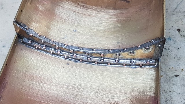 20190526_180413 20190526_180413 by Anne Froud, on Flickr  20190526_180431 20190526_180431 by Anne Froud, on Flickr  20190526_180442 20190526_180442 by Anne Froud, on Flickr  20190526_180459 20190526_180459 by Anne Froud, on Flickr The intention is to just leave the plate as it is so as to provide a baffle in the tank. I don't think there's any benefit from adding angles and riveting it to the outer wrapper. It's massively strong as it is and it just makes more work for no real benefit. |
|
|
|
Post by d304 on May 26, 2019 21:51:32 GMT
Hi Roger. I'm back on Photobucket now they have come to their senses. I have just paid my annual fee of £12.00. It was worth it to keep all the old photos in my build thread available. I just have the hastle of loading all photos I want to upload, into Paintshop Pro (similar to Photoshop) and reduce the file size from 52M standard to 4M, for a quick upload. Keep up the good work. We all avidly follow your build thread! Bob. Hi Bob Batch resize all your images. Create a new folder for all your resized images so you keep the original full resolution images. You should be able to set image size and compression. regards David |
|
|
|
Post by Roger on May 26, 2019 22:04:32 GMT
Out of interest, the pictures I'm currently taking are 9.1MP using the smart phone which are uploaded to Flickr at that resolution. There's little benefit in taking pictures at a higher resolution than that in my opinion, unless you're going to digitally zoom in on one part of the photo or you are going to project it onto a huge screen. The pictures you see here are 640x360 so about 5.8MP which is still more than adequate. The Phosphor Bronze 'O' ring flange for the balance pipe were held in place by riveting over the corners. That's why the thickness was made greater than the Brass wrapper.  20190526_211513 20190526_211513 by Anne Froud, on Flickr This is some of the high temperature solder I bought which is ludicrously large ie about 3mm diameter. I've crushed it in the vice and cut it into strips with tin snips... 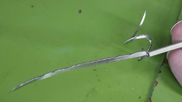 20190526_213621 20190526_213621 by Anne Froud, on Flickr ... then laid it on the joints in various places. 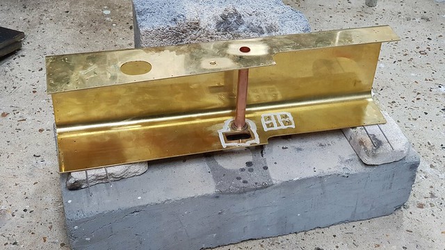 20190526_214732 20190526_214732 by Anne Froud, on Flickr I made a Brass collar for the pipe that carries the water to the top feed to increase the area of the joint. The four screws on the right are holding on the tank support plate. They're welded on the real thing. I might add a fillet of soft solder later to the underside to give that effect. Again, I used Comsol flux on this and swirled some around the molten joints to make sure they were sound.  20190526_215431 20190526_215431 by Anne Froud, on Flickr I've added way more than necessary really, but it doesn't want to penetrate the joint as much as 60/40 solder so the fillet is perhaps a little bigger because of that. You certainly need to get this noticeably hotter than for the 60/40 solder, so when this assembly is added to the back it's definitely not going to melt.  20190526_220049 20190526_220049 by Anne Froud, on Flickr  20190526_221803 20190526_221803 by Anne Froud, on Flickr You can see a blob of solder in the above view which was unfortunately on the 'O' ring mating surface. Rather than heat this up and wiping it away, I opted to use a scalpel to get it gone. Having cleaned this up a bit more, I can see that there's a small area on the bottom RH side of the 'O' ring seal that hasn't properly created a fillet. I'll have to re-heat that and add a bit more solder there.  20190526_223201 20190526_223201 by Anne Froud, on Flickr The top end of the tube has been left free for the time being because the back needs to go on first and the tube needs to be movable for that. |
|
|
|
Post by 92220 on May 27, 2019 8:33:09 GMT
Hi Roger.
My camera resolution is 52M so is just a bit high for Photobucket!!
I've just bought a high temperature soldering station that ranges from 180C to 420C. What is the high temp solder you bought? Those fillets are neat! What flux did your use? I assume it's a special high temp flux, or is the Comsol?
Bob.
|
|
|
|
Post by 92220 on May 27, 2019 8:35:48 GMT
Hi Roger. I'm back on Photobucket now they have come to their senses. I have just paid my annual fee of £12.00. It was worth it to keep all the old photos in my build thread available. I just have the hastle of loading all photos I want to upload, into Paintshop Pro (similar to Photoshop) and reduce the file size from 52M standard to 4M, for a quick upload. Keep up the good work. We all avidly follow your build thread! Bob. Hi Bob Batch resize all your images. Create a new folder for all your resized images so you keep the original full resolution images. You should be able to set image size and compression. regards David Hi David. Thanks for that suggestion. I didn't know I could batch resize. I shall have to try that. It will save a mass of time uploading to Photobucket. I do always keep the original res photo and keep the reduced file in a separate folder. Bob. |
|


